Sélection de la langue

Search

Sommaire du brevet 2012801 

Énoncé de désistement de responsabilité concernant l'information provenant de tiers

Une partie des informations de ce site Web a été fournie par des sources externes. Le gouvernement du Canada n'assume aucune responsabilité concernant la précision, l'actualité ou la fiabilité des informations fournies par les sources externes. Les utilisateurs qui désirent employer cette information devraient consulter directement la source des informations. Le contenu fourni par les sources externes n'est pas assujetti aux exigences sur les langues officielles, la protection des renseignements personnels et l'accessibilité.

Disponibilité de l'Abrégé et des Revendications

L'apparition de différences dans le texte et l'image des Revendications et de l'Abrégé dépend du moment auquel le document est publié. Les textes des Revendications et de l'Abrégé sont affichés :

  • lorsque la demande peut être examinée par le public;
  • lorsque le brevet est émis (délivrance).
(12) Demande de brevet: (11) CA 2012801
(54) Titre français: SERINGUE JETABLE
(54) Titre anglais: SELF DISCARDING SYRINGE
Statut: Réputée abandonnée et au-delà du délai pour le rétablissement - en attente de la réponse à l’avis de communication rejetée
Données bibliographiques
(51) Classification internationale des brevets (CIB):
  • A61M 03/00 (2006.01)
  • A61M 05/315 (2006.01)
  • A61M 05/50 (2006.01)
(72) Inventeurs :
  • ARCUSIN, CARLOS EDUARDO (Argentine)
(73) Titulaires :
  • CARLOS EDUARDO ARCUSIN
(71) Demandeurs :
(74) Agent: SMART & BIGGAR LP
(74) Co-agent:
(45) Délivré:
(22) Date de dépôt: 1990-03-22
(41) Mise à la disponibilité du public: 1990-09-22
Licence disponible: S.O.
Cédé au domaine public: S.O.
(25) Langue des documents déposés: Anglais

Traité de coopération en matière de brevets (PCT): Non

(30) Données de priorité de la demande:
Numéro de la demande Pays / territoire Date
313,481 (Argentine) 1989-03-22

Abrégés

Abrégé anglais


ABSTRACT OF THE DISCLOSURE
A self discarding syringe which can be used only
once since just one loading operation can be performed with
it with a mean to inject, and only one ejection of the
mean contained therein because the mechanism forming the
piston and the stem controlling it, together with a run
limitating mean provided in the syringe's body, determines
that the piston, after its both ways run inside the syringe
body will stay inoperable notwithstanding the stem displa-
cement or the intention to bind the stem through external
action.

Revendications

Note : Les revendications sont présentées dans la langue officielle dans laquelle elles ont été soumises.


-7-
The embodiments of the invention in which an exclusive
property or privilege is claimed are defined as follows.
Having made the description and determined the nature
and scope of the present invention and the way the same
has to be taken to practice it is declared the invention
and exclusive property of the following wich is so claimed:
1.- A self discarding syringe, of the type constituted by
a tube ended in a spout, having a piston, characterized because
the piston is formed by two means, interconnectable and with
passing possibilities one with respect to the other, being,
selectively, one rigid and the other one elastic, and the
tube having limitating means of the piston's run in a part
of same.
2.- A self discarding syringe, according to claim 1, charac
terized because one of the means constituting the piston
is a first element having its external outline applied against
the internal wall of the tube, and having said first element
a hole in its centre.
3.- A self discarding syringe according to claim 1, characte-
rized because the other mean constituting the piston is
a second element having a geometrical conformation selected
among truncated conical, cylindrical, semicylindrical and
polygonal, being said second element selectively connectable
to said first element.
4.- A self discarding syringe, according to claim 3, charac-
terized because said second element has a stem and a cylin-
drical butt fixed in opposite positions to the faces of said

-8-
second element.
5.- A self discarding syringe according to claim 1, charac-
terized because the two means forming the piston are selec-
tively constituted, each of them, by a body of elastic material
and by a body of rigid material.
6.- A self discarding syringe, according to claim 1, charac-
terized because said run limitating means are formed by
bosses internally displayed on the walls of the tube consti-
tuting the body of the syringe at 120°between them.
7.- A self discarding syringe, according to claim 6, charac-
terized because said run limitating means are formed by
flattennings having a curved shape on the walls of the tube.
8.- A self discarding syringe, according to claim 6, charac-
terized because said run limitating means are formed by rec-
tangular flattenings on the walls of the tube.
9.- A self discarding syringe, according to claim 6, charac-
terized because said run limitating means are formed by a
jointly binding bushing to the body of the syringe containing
the stem-
10 A self discarding syringe according to claim 6, charac-
terized because the run limitating means are formed by a
flattening ot the termination of the tube of the syringe.

Description

Note : Les descriptions sont présentées dans la langue officielle dans laquelle elles ont été soumises.

~o~g~
The present invention is about a self discarding
syringe to be used in medicine field, among other fields,
or in techniques where it can be used only once.
It is already known the neecl of having syringes W}liCh
can be used only once in medicine techniques, due to reasons
oE contagion, and where no tricks albwing a rereated use of
same may be used.
Syringes known nowadays are repeated]y used although
the same were destinated as disposable elements and, therefore
only to be used once. This does not prevents tlleir re use,
therefore, the patient is not sure that this element was not
used before.
The present invention refers to a sel~ discarding
syringe which can be used only once since just une loading
operation can be performed by it, with a mean -to inject, and
only one ejection o~eration of the mean contained therein,
because 'the mechanism forming the piston and the stem
controlling it together with the run limitation mean that
the syringe body has, determines that the pistoli, aEter its
both ways rwl inside the syringe body, will st~y inoperable
notwithstanding the stem displacement or the intentlOn to
bind the stem wlth the piston through external actions.
In order to remain inoperable this new syringe has
its piston formed by two independent and complementary bodies,
One oE them is the body that frictions against the
.

2~:~2~
internal walls of the syringe along its run and the other
one is an element having a determined geometrical configuration
~his is connected to the stem and which allows to modify its
its situation with respect to the the first body when it
crosses a hole -that the first body has in the middle, and
80 the first body may be drawn in one way and pushed only
once in the opposite direction. This is possible because
one of the two bodies is flexible and the other one is rigid
and there exists a mean to limit the piston's run inside
the syringe.
The self discarding syringe, object of this invention,
is constituted by a tube shaped body with a spout in its
extrem. A piston fitting perfectly well into the cavity of
the body, runs in same. The piston is constituted by two
complementary elements. l`he first element is the one that
fits into the cavity of the syringe body and the second
eleme~ has a geometrical configuration, selected among. o
trunk conic~l cy~indrical, semicy]inclrical or polygonal
affixed to the bar performing the plston's run.
~ his seco~delement may change its location with
respect to the first element when it passes through a hole
of said first element having a smaller diameter than that
of the second element, since- in a selective way- one of
the elements is made of a flexible material and the other
of a rigid material and the syringe body has in a par~ of
same, a limitating mean for the run of the piston whose
function in to allow the second element - from which the

--3-
piston is formed - to change its location with respect to
the first element.
In order to clarify the advantages so slightly men-
tioned an to which experts will be able to add many more
and in order to make its comprehension easier with respect
to the constructive, constitutive and functional features
of this self discarding syringe invented, there is a preferred
example described below as shown in the figures, considering
that same has not a limitative character with reference to
its scope.
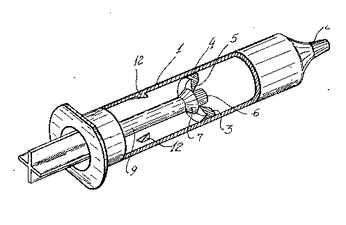
Figure I shows a sirynge according to the invention.
Figure 2 is a partially cut perspective.
Figure 3 shows a variable of the piston conformation.
Figure ~ shows another variable of the piston confor-
mation.
Figure 5 shows a cut ~ the limitating mean according
to line V-V of figure 1.-
Figures 6 and 7 show cuts of variations of the limi-
tating mean.
F~ures ~, 9, 10, 11 and 12, show the piston positions
and its -formirg elements during the syringe operation.
The self discarding syringe, as shown in the figures,
.
is constituted by a body 1 formed by a tube having a spout
in its extreme or end 2. A piston 3 isplaced inside of body 1,
being this a movable piston.

~2g~
-4-
This piston 3 is formed by a first element 4 having
a similar external outline as the inter]lal outline of the
tube in body 1 whis has in its central part a hole 5 of a
diameter slightly bigger than the diameter oE a guide-b~ltt 6
provided in tlle second element 7 W}liC}I Forms piston 3
together with element 4.
The second element 7 has the shape of a truncated
cone 8 in one of its realizations, whose smaller base is
connected to stem 9 which operates piston 3. The bigger
base of the truncated cone 8 is affixed to guide-butt 6.
The truncated cone 8 is placed with its sma]ler conical
partintrocluced in the hole S of the element 4 whel1 piston
3 is positioned over the ending of body 1 containing
spout 2.
In another realization, as shown in figure 3, the
second element has a spherical shape 10 and guide-butt 6
and stem 9 are fixed in diametrlcally opposite places of
said sphere.
Furtherlllore, as shown in igure 4, the second element
7 is formed by a semisphere 11 where stem 9 is applied in
its spherical part and guide-butt 6 is in the flat part.
This second element 7 maly also have polygonal geometrical
configurations constituting a complementary element to
form piston 3.
The body of syringe 1 has a limita~ing mean 12 for the
run, near its termination. This limitation mean may be formed

~0~01
by re-entrants made at 120among each other, as shown in
figure 5, or flattening of the tube of the body, as shown
in figures 6 and 7.
Stelll 9, which operates piston 3, may be cylindrical
or have a cross shape with an adequate termination for its use.
Figures 8 to 12 show the operation of the discarding
syringe.
When the piston is placed near spout 2 (fig. 8)which
is a necessary condition to fill the syringe, the second
element 7 is placed between the termination of body 1 and
first element 4. When the piston is taken away actioning
its stem to absorve the mean to be introduced into the syringe,
element 7 is introduced into hole 5 of body 4 forming a
watertight whole, as seen in figure 9.
When piston 3 reaches the run limitating means 12
and if one wishes to eject the mean introduced into the
syringe, the the syringe stem must continue to be operated in
the same direction until the second element 7 occupies the
position shown in figure 10. This is because one of the
elements 4 and 7 is elastic and the other is rigid.
From the position shown ln figure 10~ it is possible
to put pressure on the stem as the group of elements 4 and 7
act like a piston and the mean introduced lnto the syringe
can be ejected through the spout 2 (figure 11) up to the
end of the run ~figure 12~.

If suction is desired again, the piston does not operates
because element 7 will be separated from element 4 because
they will not be physically joined to each other (fig. 12).
Therefore, the syringe cannot be used again.
If the intention is to place element 7 in the position
of initial figure 8, this would be impossible because the
guide-butt 6 is preventing it, since it would be touching
the bottom of the syringe which will not allow element 4
to pass through hole 5.
When the present invention will be taken to practice,
no d~bt some amendments may be introduced in certain details,
without leaving aside the main principles clearly detailed
in the following claims:

Dessin représentatif
Une figure unique qui représente un dessin illustrant l'invention.
États administratifs

2024-08-01 : Dans le cadre de la transition vers les Brevets de nouvelle génération (BNG), la base de données sur les brevets canadiens (BDBC) contient désormais un Historique d'événement plus détaillé, qui reproduit le Journal des événements de notre nouvelle solution interne.

Veuillez noter que les événements débutant par « Inactive : » se réfèrent à des événements qui ne sont plus utilisés dans notre nouvelle solution interne.

Pour une meilleure compréhension de l'état de la demande ou brevet qui figure sur cette page, la rubrique Mise en garde , et les descriptions de Brevet , Historique d'événement , Taxes périodiques et Historique des paiements devraient être consultées.

Historique d'événement

Description Date
Inactive : CIB de MCD 2006-03-11
Le délai pour l'annulation est expiré 1996-09-24
Demande non rétablie avant l'échéance 1996-09-24
Réputée abandonnée - omission de répondre à un avis sur les taxes pour le maintien en état 1996-03-22
Inactive : Demande ad hoc documentée 1996-03-22
Demande publiée (accessible au public) 1990-09-22

Historique d'abandonnement

Date d'abandonnement Raison Date de rétablissement
1996-03-22
Titulaires au dossier

Les titulaires actuels et antérieures au dossier sont affichés en ordre alphabétique.

Titulaires actuels au dossier
CARLOS EDUARDO ARCUSIN
Titulaires antérieures au dossier
S.O.
Les propriétaires antérieurs qui ne figurent pas dans la liste des « Propriétaires au dossier » apparaîtront dans d'autres documents au dossier.
Documents

Pour visionner les fichiers sélectionnés, entrer le code reCAPTCHA :


Pour visualiser une image, cliquer sur un lien dans la colonne description du document. Pour télécharger l'image (les images), cliquer l'une ou plusieurs cases à cocher dans la première colonne et ensuite cliquer sur le bouton "Télécharger sélection en format PDF (archive Zip)" ou le bouton "Télécharger sélection (en un fichier PDF fusionné)".

Liste des documents de brevet publiés et non publiés sur la BDBC .

Si vous avez des difficultés à accéder au contenu, veuillez communiquer avec le Centre de services à la clientèle au 1-866-997-1936, ou envoyer un courriel au Centre de service à la clientèle de l'OPIC.


Description du
Document 
Date
(aaaa-mm-jj) 
Nombre de pages   Taille de l'image (Ko) 
Abrégé 1990-09-21 1 17
Dessins 1990-09-21 3 108
Revendications 1990-09-21 2 62
Dessins représentatifs 1990-09-21 1 16
Description 1990-09-21 6 165
Taxes 1992-03-19 1 47
Taxes 1993-03-17 1 38
Correspondance 1992-07-16 1 14
Taxes 1992-06-21 1 56
Taxes 1992-03-19 2 51
Correspondance 1992-04-23 1 34
Correspondance 1992-05-07 1 18