Sélection de la langue

Search

Sommaire du brevet 2013637 

Énoncé de désistement de responsabilité concernant l'information provenant de tiers

Une partie des informations de ce site Web a été fournie par des sources externes. Le gouvernement du Canada n'assume aucune responsabilité concernant la précision, l'actualité ou la fiabilité des informations fournies par les sources externes. Les utilisateurs qui désirent employer cette information devraient consulter directement la source des informations. Le contenu fourni par les sources externes n'est pas assujetti aux exigences sur les langues officielles, la protection des renseignements personnels et l'accessibilité.

Disponibilité de l'Abrégé et des Revendications

L'apparition de différences dans le texte et l'image des Revendications et de l'Abrégé dépend du moment auquel le document est publié. Les textes des Revendications et de l'Abrégé sont affichés :

  • lorsque la demande peut être examinée par le public;
  • lorsque le brevet est émis (délivrance).
(12) Brevet: (11) CA 2013637
(54) Titre français: AMELIORATION APPORTE A DES RAMPES DE CHARGEMENT
(54) Titre anglais: IMPROVEMENT IN LOADING RAMPS
Statut: Périmé et au-delà du délai pour l’annulation
Données bibliographiques
(51) Classification internationale des brevets (CIB):
  • E01D 15/00 (2006.01)
  • B65G 69/28 (2006.01)
(72) Inventeurs :
  • KARLSSON, GORAN (Suède)
(73) Titulaires :
  • KVISTBERGA PRODUKTER AB
(71) Demandeurs :
  • KVISTBERGA PRODUKTER AB (Suède)
(74) Agent: MARKS & CLERK
(74) Co-agent:
(45) Délivré: 1999-11-16
(22) Date de dépôt: 1990-04-02
(41) Mise à la disponibilité du public: 1990-10-03
Requête d'examen: 1996-10-21
Licence disponible: S.O.
Cédé au domaine public: S.O.
(25) Langue des documents déposés: Anglais

Traité de coopération en matière de brevets (PCT): Non

(30) Données de priorité de la demande:
Numéro de la demande Pays / territoire Date
8901161-3 (Suède) 1989-04-03

Abrégés

Abrégé anglais


An arrangement for limiting the extent to which
telescopically mounted sections can be extended is enclosed
in a chamber between each pair of sections, so as to be out
of the way of personnel handling the sections. The
arrangement comprises two mutually co-acting devices which
have the form of hollow bodies and which are intended to
engage one another when the section of a pair of sections
are extended to a maximum. The mutually facing surfaces of
the hollow bodies are preferably provided with a damping
ramp section.

Revendications

Note : Les revendications sont présentées dans la langue officielle dans laquelle elles ont été soumises.


THE EMBODIMENTS OF THE INVENTION IN WHICH AN EXCLUSIVE
PROPERTY OR PRIVILEGE IS CLAIMED ARE DEFINED AS FOLLOWS:
1. An arrangement for limiting the extensibility
between at least two telescopically assembled sections
which are particularly profiled sections forming part of a
loading ramp, and comprising mutually co-acting means
provided between each pair of sections, each pair of
sections having co-acting slide surfaces and mutually
opposing surfaces of each section, said mutually co-acting
means being enclosed in a protecting chamber defined by the
mutually opposing surfaces of the sections forming a pair
of sections, said chamber being arranged in the vicinity of
the slide surfaces of said sections, with each section
comprising an elongated section having a longitudinal
direction and at least one part having a substantially
L-shaped cross-section defining an angle part, said chamber
being configured as a channel in the immediate proximity of
the angle part of said cross-section and in the
longitudinal direction between two vertical walls, each
vertical wall being of one section of a pair of sections,
said walls being displaceable in relation to one another.
2. The arrangement according to claim 1, wherein
each of said mutually co-acting devices comprises a stop
shoe attached to a respective section, each said stop shoe
on said sections forming a pair of sections intended to

engage one another when said sections are extended to a
maximum in relation to one another.
3. The arrangement according to claim 2, wherein at
least one stop shoe in a pair of ramp sections is provided
with a damping element on a surface thereof which faces the
other stop shoe.
4. The arrangement according to claim 3, wherein
each said stop shoe has the form of a hollow body and
includes a through-passing hole forming attachment means
for said damping element.
5. The arrangement according to claim 4, wherein
said hollow body has a longitudinally extended slot which
divides said stop shoe into two leg sections to be welded
to those parts of the wall of said section defining said
chamber.
6. An arrangement for limiting the extensibility
between at least two telescopically assembled sections
which are particularly profiled sections forming part of a
loading ramp, and comprising mutually co-acting means
provided between each pair of sections, each pair of
sections having co-acting slide surfaces and mutually
opposing surfaces of each section, said mutually co-acting
means being enclosed in a protecting chamber defined by the

mutually opposing surfaces of the sections forming a pair
of sections, said chamber being arranged in the vicinity of
the slide surfaces of said sections, with each section
comprising an elongated section having a longitudinal
direction and at least one part having a substantially
L-shaped cross-section defining an angle part, said chamber
being configured as a channel in the immediate proximity of
the angle part of said cross-section and in the
longitudinal direction between two vertical walls, each
vertical wall being of one section of a pair of sections,
said walls being displaceable in relation to one another,
each of said mutually co-acting means comprising a stop
shoe attached to a respective ramp section, and in that
stop shoes on said sections forming a pair of sections
intended to engage one another when said sections are
extended to a maximum in relation to one another, at least
one stop shoe in a pair of ramp sections provided with a
damping element on a surface thereof which faces the other
stop shoe, each said stop shoe having the form of a hollow
body with a through-passing hole which forms attachment
means for said damping element.
7. The arrangement according to claim 1, wherein
said hollow body has a longitudinally extended slot which
divides said stop shoe into two leg sections to be welded
to those parts of a wall of the ramp section defining said
chamber.

8. An arrangement for limiting the extensibility
between telescopically assembled ramp sections, each ramp
section particularly profiled with a drive surface located
between two upstanding flanges for forming part of a
loading ramp, said arrangement comprising mutually
co-acting means provided between each pair of ramp sections,
each pair of ramp sections having co-acting slide surfaces
and mutually opposing surfaces, wherein said mutually
co-acting means are enclosed within a protecting chamber
configured as an enclosed channel defined by said mutually
opposing surfaces of said pair of ramp sections, a portion
of said drive surface of one ramp section and an
undersurface portion opposite a portion of said drive
surface of said other of said pair of ramp sections, with
said length of said enclosed channel protecting chamber
configuration being defined by said mutually co-acting
means, said chamber being arranged in the vicinity of said
slide surfaces of said ramp sections, with a slide surface
of one ramp section of a ramp section pair being elevated
above said drive surface of said one ramp section, with
each ramp section comprising an elongated section having a
longitudinal direction and at least one part with a
substantially L-shaped cross-section defining an angle
part, said chamber being located in the immediate proximity
of said angle part of said cross-section and enclosed to
prevent accidental operator access thereto during use, said

ramp sections being displaceable in relation to one
another.
9. The arrangement according to claim 8, wherein
each of mutually co-acting means comprises a stop shoe
attached to a respective ramp section, each said stop shoe
on said sections forming a pair of sections intended to
engage one another when said sections are extended to a
maximum in relation to one another.
10. The arrangement according to claim 9, wherein at
least one stop shoe in a pair of ramp sections is provided
with a damping element on a surface thereof which faces the
other stop shoe.
11. A telescopic loading ramp, comprising:
at least two ramp elongated sections forming a pair of
sections;
each ramp section particularly profiled with a drive
surface located between two upstanding flanges for forming
part of a loading ramp, each ramp elongated section having
a longitudinal direction along the length thereof and a
cross-section with at least one portion having a
substantially L-shape defining an angle part;
each pair of ramp sections having co-acting slide
surfaces and mutually opposing surfaces of said upstanding
flanges of each ramp section defining therebetween a

protecting chamber in the vicinity of said slide surfaces,
said chamber being configured as a channel extending in the
longitudinal direction between said mutually opposing
surfaces in the immediate proximity of said angle part,
said sections of each pair being displaceable in relation
to one another; and
a pair of co-acting stop shoes provided between each
pair of ramp sections, for limiting the extensibility
between telescopically assembled sections, each stop shoe
being coupled to one of said ramp sections and enclosed
within said protecting chamber.
12. The telescopic loading ramp according to claim
11, wherein each stop shoe is attached to a ramp section so
as to engage a stop shoe on the other of said pair of ramp
sections when said sections are extended to a maximum
position with respect to one another.
13. The telescopic loading ramp according to claim
12, further including a damping element attached to at
least one stop shoe on a surface thereof which faces said
stop shoe on the other of said pair of ramp sections.

Description

Note : Les descriptions sont présentées dans la langue officielle dans laquelle elles ont été soumises.

1
Improvement in loading ramps
Technical field
The present invention relates to telescopically assembled
ramp sections, and particularly to profiled ramp sections which
form part of a loading ramp. More particularly, the invention
relates to an arrangement which is operative to restrict extens-
ibility between the ramp sections) wherein mutually co-acting
devices are provided between each pair of ramp sections.
Background Art
Extensible loading ramps of the kind used in pairs as supports
for the wheels of vehicles to be transferred from one plane to
another are well known to the art, far instance from Swedish '
Patent 8004947-1 (publication No. 423 223). In the case of these
known ramps, the extensibility between the ramp sections is
restricted by mutually co-acting devices provided on the ends of
the upstanding side members of said ramp sections, as .illustrated
in Fig. 3 of Swedish Patent Application 8502'1.66-3, far instance.
These ramps are provided with sheet-metal and/or rod-like~stop
devices which engage one another when the ramp is extended to its
maximum, therewith preventing further extension of the ramp.
These stop devices are directed in towards the carriageway on
respective ramps and therewith are liable to present an obstacle
~.o passage of the vehicles .al'ong said'ramps. A more serious draw-
back, however, is'that stop devices of this kind have caused
accidents or have been the cause of accidents, since the stop
devices are within reach of the personnel handling the ramp, and
consequently'are liable to cause-squeezing, pinching ar squashing
of the hands and fingers, for instance when extending the ramp.
~ gummar~t of f.he invention w
The object of the present invention is to avoid the aforesaid
drawbacks while, at the same time, endeavouring to provide more
stable stopping devices which, advantageously, will not give rise
to unnecessary noise.
These objects are achieved by enclosing the stop devices or
limiting devices co--acting with the aforedescribed telescopically

,~~.~:a~~3. ~~.~
2
assembled ramp sections in a protecting chamber which is defined
by the mutually facing surfaces of the ramp sections forming a
pair of ramp sections. The chamber is arranged in the vicinity of
the slide-surfaces of the ramp sections.
Advantageous embodiments and further developments of the
invention are set forth in the depending claims.
Description of Preferred Embodiments
The inventive arrangement will now be described in more detail
with reference to the accompanying drawings, in which
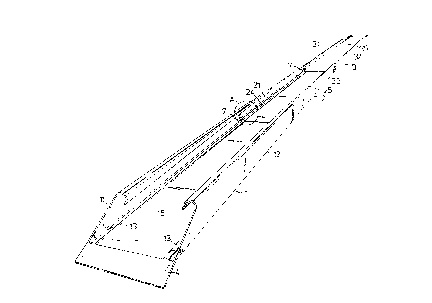
Fig. 1 illustrates an embodiment of the inventive arrangement
applied to a three-section loading ramp, shown in its extended
state;
Fig. lA illustrates in larger scale, and partly in section, a
detail between two of the extended ramp sections marked A in Fig.
1, and illustrates the co-action between the stop jaws provided in
the inventive arrangement;
Fig. 2 is a cross-sectional view of the three-section loading
ramp of Fig. 1, and shows the ramp in its collapsed state;
Figs. 3a-c illustrate the~substantially L-shaped cross-section
of respective ramp sections in the loading ramp illustrated in
Fig. i;
Fig. d illustrates a two-section loading ramp of modified
cross-section and provided with the inventive arrangement; and
Fig. 5 illustrates a cross-sec~ion'of a two-section loading
ramp which corresponds to the cross-section illustrated in Fig. 2.
Telescopic loading ramps comprise two or more mutually
collapsible and extensible ramp sections. Figs. 1 and 2 illustrate
one such three-section loading ramp which, comprises three ramp
sections 1, 2 and 3. Fig. 1 shows the loading ramp extended, with
the bottom ramp section 3 being shbwn furthest away and being
intended to zest on the ground surface or the floor. The ramp
section 1 nearest the viewer in Fig. 1 is provided with a tongue 4
which is intended to rest on the edge of a loading dock or plat-
form, on the chassis of the passenger compartment of a minibus or
the like. The three-part loading ramp has a L~-shaped cross-section

3
as illustrated in Fig. 2, this Figure showing the ramp in its
collapsed state.
Each of the ramp sections 1, 2, 3 has upstanding f7.anges 1i,
21, 31, 12, 22, 32 which are gently arched along their upper side
edges. The flanges 31, 32 of the bottom ramp-section 3 are
bevelled down, so that vehicles such as wheelchairs, garden equip- '
ment or the like to be rolled up on the ramp will not be caught up
or impeded by the ~unction,from the flat ground surface to the
often pronouncedly inclined loading ramp. Each ramp section 1, 2,
3 is provided with slide surface intended for co-action with mutu-
ally ad]acent ramp sections. Thu s, two mutually adjacent ramp
sections 1, 2 or 2, 3 can be considered to form ramp section
pairs l-2 and 2-3, respectively. The ramp section 1 has solely
upwardly facing slide surfaces l3 which are intended to co-act
with downwardly facing slide surfaces 23 on the second ramp aec-
Lion 2. The second ramp section 2 is also provided with upwardly
facing slide surfaces 24 which are intended to co-act with the
downwardly facing slide surfaces 33 on the third ramp section 3.
The slide surfaces 13, 23, 24~, 33~are disposed in the immediate
vicinity of the junction point, i.e. the angled part between the
drive surfaces 15, 25, 35 on the ramp sections 1, 2, 3 and the
flanges ll, 12, 21, 22, 31, 32 on said sections. The drive surface
15, 25,'35 thus forms an L-shaped cross-section with each flange
11, 12, 21) 22, 31) 32 on respective ramp sections 1, 2; 3. The
glide sLtrfacea 13, 23, 24, 33 and the arched upper sides of the
,flanges enable the ramp sections i, 2, 3 to move telescopically
one wifi.hin the other, the ramp section 1 having the largest width
and height dimensions, whereas the ramp section 3 has the smallest
width and height dime~asions, so that the ramp section 3 can be
inserted into the ramp section 2,vwhich can be inserted into the
ramp section 1
In order to limit the extent to which eabh ramp section l, 2,
3 can be extended, each ramp section 1, 2; 3 is configured, in
accordance with the invention, with a stop shoe or block 5) best
seen frown Pig. 1F~. These stop shoes 5 are mounted adjacent at
least one flange of respective ramp sections 1, 2, 3. The stop

20~.3~~'~
4
shoes 5 are attached to respective ramp sections 1, 2, 3 by means
of welds 6 on the flange wall in the immediate vicinity of 'the
angle part of the L-shaped cross-section. The mutually,facing.
flange walls of two ramp sections in a pair of ramp sections 1-2,
2-3, form at said angle part a chamber 7 in which the stop shoes 5
are readily accommodated. The stop shoes 5 on two ramp sections
within a pair of ramp sections 1-2, 2-3, are disposed so as to
engage one another when said ramp section pair has been extended
to a maximum, such as to prevent further extension.
Fig. 2 illustrates an embodiment of a. three-section loading
ramp in which stop shoes 5 are mounted on both flange sides of
respective ramp sections 1, 2, 3. It will be understood, however,
that it will suffice to provide step shoes solely on one flange
side, as evident from Figs. 4 and 5, which illustrate a two sec-
tion loading ramp in which respective ramp sections l', 2' have a
modified crass-sectional shape.
This modified loading ramp which may, of course, comprise
three or more ramp sections, has a flange side on which stop shoes
5 are mounted. This flange side has the same configuration as
those described above with reference to Figs. 1 and 2 and has
consequently been identified with the same reference sign. The
opposite flange side of the modified loading ramp presents support
edges 12', 22', the height of which is roughly half of the height
o.f the opposite flange, so as"to enable vehicles fitted with small
wheels and/or having a low chassis to pass the loading ramp; while
the support edges 12', 22' still prbvide Steering support for
those vehicles to be driven up on the ramp.
The stop shoes 5 are configured as a hollow body provided
with a longitudinally extending slot 51 which divides the hollow
body into two beg sect~.ons 52,53."The leg sections 52, 53 are
adapted for welding (6> onto respective flange walla, as clearly
shown in Figs. 3a-c. Fig. 3a illustrates the substantially
L-shaped cross-section of the ramp section 1 or 1'. Fig. 3b
illustrates a correspondingly substantially L-shaped crass-section
of the ramp section 2 or 2', while Fig. 3c illustrates the sub
stantially L-shaped cross-section of the ramp section 3.

5
As will be be seen from Fig. lA, the mutually facing support
surfaces of the stop shoes 5 are conveniently configured with
damping elements 8. The damping elements 8 are made of,rubber or
some similar resilient material and can be attached in through
holes 9 provided in the stop shoes 5.
Both the ramp sections 1, 2, 3 or 1', 2' and the stop shoes 5
may be manufactured advantageously from aluminium, for instance by
continuous casting methods...
Although the inventive arrangement has been described in the
aforegoi.ng with reference to loading ramp sections, it will be
understood that the inventive arrangement can also be used with
other telescopically extensible sections. Furthermore, the hollow
body provided with a damping element can also be given other con-
figurations in accordance with the inventive concept.

Dessin représentatif
Une figure unique qui représente un dessin illustrant l'invention.
États administratifs

2024-08-01 : Dans le cadre de la transition vers les Brevets de nouvelle génération (BNG), la base de données sur les brevets canadiens (BDBC) contient désormais un Historique d'événement plus détaillé, qui reproduit le Journal des événements de notre nouvelle solution interne.

Veuillez noter que les événements débutant par « Inactive : » se réfèrent à des événements qui ne sont plus utilisés dans notre nouvelle solution interne.

Pour une meilleure compréhension de l'état de la demande ou brevet qui figure sur cette page, la rubrique Mise en garde , et les descriptions de Brevet , Historique d'événement , Taxes périodiques et Historique des paiements devraient être consultées.

Historique d'événement

Description Date
Inactive : CIB de MCD 2006-03-11
Le délai pour l'annulation est expiré 2005-04-04
Lettre envoyée 2004-04-02
Inactive : Lettre officielle 2000-03-28
Accordé par délivrance 1999-11-16
Inactive : Page couverture publiée 1999-11-15
Inactive : Grandeur de l'entité changée 1999-09-08
Inactive : Taxe finale reçue 1999-08-13
Préoctroi 1999-08-13
Un avis d'acceptation est envoyé 1999-03-08
Lettre envoyée 1999-03-08
Un avis d'acceptation est envoyé 1999-03-08
Inactive : Renseign. sur l'état - Complets dès date d'ent. journ. 1999-02-17
Inactive : Dem. traitée sur TS dès date d'ent. journal 1999-02-17
Inactive : Approuvée aux fins d'acceptation (AFA) 1999-01-18
Toutes les exigences pour l'examen - jugée conforme 1996-10-21
Exigences pour une requête d'examen - jugée conforme 1996-10-21
Demande publiée (accessible au public) 1990-10-03

Historique d'abandonnement

Il n'y a pas d'historique d'abandonnement

Taxes périodiques

Le dernier paiement a été reçu le 1999-03-24

Avis : Si le paiement en totalité n'a pas été reçu au plus tard à la date indiquée, une taxe supplémentaire peut être imposée, soit une des taxes suivantes :

  • taxe de rétablissement ;
  • taxe pour paiement en souffrance ; ou
  • taxe additionnelle pour le renversement d'une péremption réputée.

Veuillez vous référer à la page web des taxes sur les brevets de l'OPIC pour voir tous les montants actuels des taxes.

Historique des taxes

Type de taxes Anniversaire Échéance Date payée
TM (demande, 8e anniv.) - petite 08 1998-04-02 1998-03-26
TM (demande, 9e anniv.) - petite 09 1999-04-02 1999-03-24
Taxe finale - générale 1999-08-13
TM (brevet, 10e anniv.) - générale 2000-04-03 2000-03-20
TM (brevet, 11e anniv.) - générale 2001-04-02 2001-03-19
TM (brevet, 12e anniv.) - générale 2002-04-02 2002-03-20
TM (brevet, 13e anniv.) - générale 2003-04-02 2003-03-07
Titulaires au dossier

Les titulaires actuels et antérieures au dossier sont affichés en ordre alphabétique.

Titulaires actuels au dossier
KVISTBERGA PRODUKTER AB
Titulaires antérieures au dossier
GORAN KARLSSON
Les propriétaires antérieurs qui ne figurent pas dans la liste des « Propriétaires au dossier » apparaîtront dans d'autres documents au dossier.
Documents

Pour visionner les fichiers sélectionnés, entrer le code reCAPTCHA :


Pour visualiser une image, cliquer sur un lien dans la colonne description du document. Pour télécharger l'image (les images), cliquer l'une ou plusieurs cases à cocher dans la première colonne et ensuite cliquer sur le bouton "Télécharger sélection en format PDF (archive Zip)" ou le bouton "Télécharger sélection (en un fichier PDF fusionné)".

Liste des documents de brevet publiés et non publiés sur la BDBC .

Si vous avez des difficultés à accéder au contenu, veuillez communiquer avec le Centre de services à la clientèle au 1-866-997-1936, ou envoyer un courriel au Centre de service à la clientèle de l'OPIC.


Description du
Document 
Date
(aaaa-mm-jj) 
Nombre de pages   Taille de l'image (Ko) 
Page couverture 1994-04-01 1 16
Abrégé 1994-04-01 1 17
Dessins 1994-04-01 3 91
Revendications 1994-04-01 1 50
Description 1994-04-01 5 222
Abrégé 1999-01-06 1 15
Revendications 1999-01-06 6 203
Page couverture 1999-11-08 1 34
Dessin représentatif 1999-11-08 1 11
Avis du commissaire - Demande jugée acceptable 1999-03-08 1 164
Avis concernant la taxe de maintien 2004-05-31 1 173
Correspondance 1999-08-13 1 31
Taxes 2000-04-10 1 31
Taxes 1997-03-24 1 63
Taxes 1996-03-25 1 54
Taxes 1994-03-24 1 50
Taxes 1995-03-28 1 64
Taxes 1993-03-23 1 51
Taxes 1992-03-25 1 32
Correspondance de la poursuite 1996-10-21 1 42
Demande de l'examinateur 1998-06-02 1 38
Correspondance de la poursuite 1998-12-02 2 45
Correspondance de la poursuite 1997-04-29 1 33
Correspondance reliée au PCT 1991-08-23 1 20
Courtoisie - Lettre du bureau 1992-03-17 1 58