Sélection de la langue

Search

Sommaire du brevet 2013956 

Énoncé de désistement de responsabilité concernant l'information provenant de tiers

Une partie des informations de ce site Web a été fournie par des sources externes. Le gouvernement du Canada n'assume aucune responsabilité concernant la précision, l'actualité ou la fiabilité des informations fournies par les sources externes. Les utilisateurs qui désirent employer cette information devraient consulter directement la source des informations. Le contenu fourni par les sources externes n'est pas assujetti aux exigences sur les langues officielles, la protection des renseignements personnels et l'accessibilité.

Disponibilité de l'Abrégé et des Revendications

L'apparition de différences dans le texte et l'image des Revendications et de l'Abrégé dépend du moment auquel le document est publié. Les textes des Revendications et de l'Abrégé sont affichés :

  • lorsque la demande peut être examinée par le public;
  • lorsque le brevet est émis (délivrance).
(12) Brevet: (11) CA 2013956
(54) Titre français: METHODE DE FIXATION DES EXTREMITES D'UN ROULEAU TENDEUR DE MATERIAU D'EMBALLAGE
(54) Titre anglais: MANNER OF ROTATABLY MOUNTING A BALE WRAPPING MATERIAL SPREADER ROLL TO SUPPORT WALLS
Statut: Périmé et au-delà du délai pour l’annulation
Données bibliographiques
(51) Classification internationale des brevets (CIB):
  • A01F 15/08 (2006.01)
  • A01F 15/07 (2006.01)
  • F16C 3/02 (2006.01)
  • F16C 13/02 (2006.01)
  • F16C 35/06 (2006.01)
  • F16C 35/063 (2006.01)
(72) Inventeurs :
  • ARDUESER, WILLIAM ALBERT (Etats-Unis d'Amérique)
  • ANSTEY, HENRY DENNIS (Etats-Unis d'Amérique)
(73) Titulaires :
  • DEERE & COMPANY
(71) Demandeurs :
  • DEERE & COMPANY (Etats-Unis d'Amérique)
(74) Agent: BORDEN LADNER GERVAIS LLP
(74) Co-agent:
(45) Délivré: 1993-05-11
(22) Date de dépôt: 1990-04-05
(41) Mise à la disponibilité du public: 1990-12-23
Requête d'examen: 1990-04-05
Licence disponible: S.O.
Cédé au domaine public: S.O.
(25) Langue des documents déposés: Anglais

Traité de coopération en matière de brevets (PCT): Non

(30) Données de priorité de la demande:
Numéro de la demande Pays / territoire Date
07/370,536 (Etats-Unis d'Amérique) 1989-06-23

Abrégés

Abrégé anglais


MANNER OF ROTATABLY MOUNTING A BALE WRAPPING
MATERIAL SPREADER ROLL TO SUPPORT WALLS
Abstract of the Disclosure
A wrap material spreader roll includes a smooth,
cylindrical tube having spiral flights at opposite end
portions thereof formed from spirally wound wires of circular
cross-section, the wires having respective inner ends defined
by a radially inwardly projecting portion which is received in
a respective hole provided in the tube. The spreader roll is
mounted to opposite support walls by respective bolts having
hexagonal heads received in hexagonal bores provided in the
inner races of a pair of roller bearings that are pressed into
the opposite ends of the tube, the bolts having respective
threaded stems received in keyhole-shaped holes provided in
the walls and having nuts received thereon.

Revendications

Note : Les revendications sont présentées dans la langue officielle dans laquelle elles ont été soumises.


THE EMBODIMENTS OF THE INVENTION IN WHICH AN EXCLUSIVE
PROPERTY OR PRIVILEGE IS CLAIMED ARE DEFINED AS FOLLOWS:
1. In a combination of a roll assembly and structure
for rotatably supporting the same, wherein the roll assembly
includes a cylindrical tubular roll and said structure for
rotatably supporting including a bearing pressed into each end
of the roll and having an inner race provided with a non-
circular opening therethrough and receiving a complimentary
shaped member which is secured to an adjacent support, the
improvement comprising: said member being a standard bolt
having a non-circular head received in the bearing and having
a threaded stem extending through the support and having a nut
received thereon.
2. In a combination of a roll assembly and structure
for rotatably supporting the same as defined in claim 1
wherein the non-circular opening in the bearing is hexagonal
and wherein the bolt has a hexagonal head.
3. In a combination of a roll assembly and structure
for rotatably supporting the same as defined in claim 1
wherein the support is in the form of a sidewall; and said
sidewall being provided with a keyhole-shaped opening oriented
with a larger portion above a smaller portion thereof,
whereby, in the mounting of at least one end of the roll to
the sidewall, the bolt may be first pressed into the bearing
in the end of the roll, the nut screwed loosely onto the stem
of the bolt, the roll then lifted and manipulated to insert
the nut through the larger portion of the keyhole-shaped
opening and to lower the stem into the smaller portion of the
keyhole-shaped opening and the nut tightened to hold the roll
in place.
4. In a combination including a roll assembly and
structure for rotatably supporting the same as defined in
claim 3 wherein the opening in the bearing is hexagonal and
the bolt is a standard bolt having a hexagonal flange head.
5. In a combination including a roll assembly and a
structure for rotatably mounting the same wherein the roll
assembly includes a cylindrical member and said structure

includes a roller bearing pressed into the opposite ends of
the member and including an inner race having a non-circular
hole extending therethrough, the improvement comprising: a
standard bolt of a type having a head shaped complimentary to
and received in said hole of each bearing; said bolt having a
threaded stem projecting away from an adjacent bearing; a
support wall being located adjacent the opposite ends of the
roll and provided with an opening receiving the stem of an
adjacent bolt; and a nut being received on each stem.
6. A combination including a roll assembly and
structure for rotatably mounting the same as defined in claim
5 wherein said hole of each bearing is hexagonal.
7. A combination including a roll assembly and
structure for mounting the same as defined in claim 6 wherein
said standard bolt has a flange head and said nut is a flange
nut.
8. A combination including a roll assembly and
structure for mounting the same as defined in claim 5 wherein
the opening in the wall is keyhole-shaped with a smaller
portion of the opening being located below a larger portion
thereof, whereby, in mounting the roll to the walls, one of
the bolts with one of the nuts loosely screwed thereonto may
be installed with its head in one of the bearings and the roll
lifted between the walls and canted to insert the installed
nut through the larger portion of one of the openings in one
of the walls, the stem of the one bolt being lowered into
place in the smaller portion of the opening while positioning
the roll to permit the other bolt to be inserted through the
upper portion of the other key-hole opening in the other wall,
and into the bearing at the other end of the roll, the other
nut then being screwed onto the stem of this bolt and both
nuts tightened to hold the roll in place.
9. A combination including a roll assembly and
structure for mounting the same as defined in claim 8 wherein
the hole provided in each bearing is hexagonal and each bolt
has a hexagonal head received in a respective hole.

10. A combination including a roll assembly and
structure for mounting the same as defined in claim 9 wherein
each bolt has a flange head and each nut is a flange nut.

Description

Note : Les descriptions sont présentées dans la langue officielle dans laquelle elles ont été soumises.

2~3~
,,
MANNER OF ROTATABLY MOUNTING A BALE WRAPPING
MATERIAL SPREADER ROLL TO SUPPORT WALLS
sackaround of the Invention
The present invention relates to a spreader roll
incorporated in a mechanism for feeding wrap material, such as
plastic sheeting or net, for enveloping large round bales,
formed in a bale-forming chamber and more particularly relates
to the mode of rotatably mounting such a roll to support walls
at opposite ends thereof.
Conventionally, spreader rolls are constructed of a
smooth cylindrical tube having spiral flighting, of opposite
hand, located on opposite end portions of the tube. These
rolls extend between and are rotatably supported by a pair of
support walls by structure including a shaft of hexagonal
cross-section extending through the center of the tube and
through hexagonal openings provided in the inner race of
roller bearings pressed into opposite ends of the tube, the
shaft being held in place by bolts extending through the walls
and screwed into threaded openings provided in the opposite
ends of the shaft. While this mode of mounting the spreader
rolls is effective, the support shaft represents a relatively

2~
expensive part of the spreader roll assembly and the mounting
of the roll is difficult for one person to achieve without
using a hoist since the roll has to be held in alignment with
the hole~ in both walls while the bolts are inserted.
Summary of the Invention
According to the present invention there is provided an
improved spreader roll assembly and more particularly there i8
provided an improved w2y of rotatably mounting a cylindrical
tubular spreader roll to supports located at opposite end~
thereof.
An object of the invention is to provide a cylindrical
tubular spreader roll which is simply and inexpensively
mounted to a support structure in a manner permitting free
rotation of the roll.
A more specific object of the invention is to rotatably
mount a roll, of the aforementioned tubular type, in a manner
such that a pair of standard bolts having non-circular heads
are provided as the sole support for the roll, this object
being accomplished by inserting the heads of the bolts into
complimentary-shaped openings provided in the inner races of a
pair of bearings pressed into the opposite end~ of the roll.
A further object of the invention is to provide a roll
mounting which permits the roll to be installed by one person,
this object being accomplished by mounting the roll to
sidewalls using standard bolts in the manner described above
and by providing keyhole-shaped holes in the sidewalls, the
mounting of the roll then being accomplished by inserting the
head of one of the bolts into one of the bearings, by screwing
a nut onto the stem of the bolt and then by lifting and
canting the roll to insert the nut through the larger upper
portion of the key-hole shaped hole and then by permitting the
stem of the bolt to drop into the smaller lower portion of the
hole while lifting the roll into alignment with the hole in
the opposite sidewall whereupon the other bolt is inserted
through the latter-mentioned hole and then into the other
bearing.

2 ~ 6
These and other objects will become apparent from a
reading of the ensuing description together with the appended
drawing.
Brief Description of the Drawing
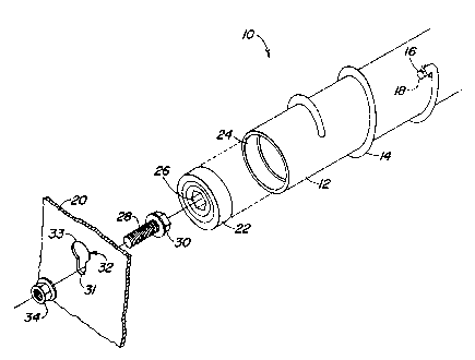
S The sole figure is a partially exploded perspective view
of an end portion of a spreader roll constructed in accordance
with the principles of the present invention and showing the
manner of rotatably mounting the roll.
Description of the Preferred Embodiment
Referring now to the dxawing, there is shown an end
section of a bale wrap material spreader roll 10 including a
smooth tube 12 having spiral flighting 14 thereon for engaging
wrap material and augering it toward the outer end of tube, it
being noted that similar but oppositely wound flighting is
positioned on the opposite end portion of the tube for
augering the wrap material towards the opposite end of the
tube. In this way the wrap material is spread across the
length of the roll 10 by the action of the flighting.
The flighting 1~ comprises a spirally wound wire,
preferably but not necessarily of circular cross-section,
which i8 wound, when free of the tube 12, to a diameter
slightly less than that of the outside diameter of the tubc 80
that the wire will tightly engage the periphery of the tube
when mounted thereon, such mounting being accomplished by
fixturing the spirally wound wire in a manner permitting it to
be forcibly "unwound~ 80 as to increase its internal diameter
to permit the insertion of the tube thereinto. The tube 12 is
provided with an aperture 16 spaced lengthwise from the end of
the tube and, in addition to being spirally wound, the wire is
formed so as to have a radially inwardly projecting end 18
that is received in the aperture 16.
Rotation of the spreader roll 10 is caused by its
frictional engagement with wrap material as the latter is
pulled from a supply roll by driven feed rolls or by a bale
being rotated in the bale-forming chamber. The spreader roll
10 extends between opposite support walls 20 (only one shown)
and is rotatably supported thereby through identical means

2 ~
including a roller bearing 22 having its outer race pressed
into an annular recess 24 provided inside the end of the tube
12 and having a hexagonal bore 26 provided through its inner
race. The mounting of each end is completed by a flange head
bolt 28 having a hexagonal head 30 tightly received in the
bore 26 of the inner race of the bearing 22, with a threaded
stem of the bolt extending outwardly through a smaller lower
portion 31 of a keyhole-shaped opening 32, having a larger
portion 33 located vertically above the portion 31, provided
in the support wall 18 and with a nut 34 being received on the
stem.
Thus, it will be appreciated that the common or standard
flange head bolts 28 provide an effective and inexpensive way
of rotatably supporting the spreader roll 10 from the support
15 walls 20. While these bolts have been described as having a
hexagonal head, any standard, non-circular head, for example a
square head will also work if mated with a bearing having an
inner race opening shaped complimentary thereto.
The mounting of the roll 10 to the support walls 20 is
20 facilitated by the key-hole shaped openings 32 which permit
one of the bolts 28 to be installed in one of the bearings 22
with one of the nuts 34 loosely screwed onto the end of the
bolt prior to the roll being lifted, the roll then being
placed between the support walls 20 and canted for obtaining
25 clearance and then manipulated for inserting the nut out
through the larger upper portion 33 of the key-hole shaped
opening 32. This bolt 28 is then permitted to lower with its
stem then being disposed in the smaller key-hole opening
portion 31 and the roll 10 is then moved so as to permit the
30 other bolt to be inserted through the larger upper portion of
the key-hole opening in the other of the walls 20 and
installed in the other of the bearings, the roll then being
lowered to place the bolt stem in the lower key-hole opening
portion. The other nut can then be installed on this bolt and
35 both nut~ tightened to secure the roll in place.
It should be noted that, while the description contained
hereinabove speaks of the invention as being applied to the

mounting of a spreader roll, the invention can be applied to
the mounting of other types of rolls without departing from
the principles thereof.
.

Dessin représentatif
Une figure unique qui représente un dessin illustrant l'invention.
États administratifs

2024-08-01 : Dans le cadre de la transition vers les Brevets de nouvelle génération (BNG), la base de données sur les brevets canadiens (BDBC) contient désormais un Historique d'événement plus détaillé, qui reproduit le Journal des événements de notre nouvelle solution interne.

Veuillez noter que les événements débutant par « Inactive : » se réfèrent à des événements qui ne sont plus utilisés dans notre nouvelle solution interne.

Pour une meilleure compréhension de l'état de la demande ou brevet qui figure sur cette page, la rubrique Mise en garde , et les descriptions de Brevet , Historique d'événement , Taxes périodiques et Historique des paiements devraient être consultées.

Historique d'événement

Description Date
Inactive : CIB de MCD 2006-03-11
Le délai pour l'annulation est expiré 2000-04-05
Lettre envoyée 1999-04-06
Accordé par délivrance 1993-05-11
Demande publiée (accessible au public) 1990-12-23
Toutes les exigences pour l'examen - jugée conforme 1990-04-05
Exigences pour une requête d'examen - jugée conforme 1990-04-05

Historique d'abandonnement

Il n'y a pas d'historique d'abandonnement

Historique des taxes

Type de taxes Anniversaire Échéance Date payée
TM (brevet, 8e anniv.) - générale 1998-04-06 1998-04-03
Titulaires au dossier

Les titulaires actuels et antérieures au dossier sont affichés en ordre alphabétique.

Titulaires actuels au dossier
DEERE & COMPANY
Titulaires antérieures au dossier
HENRY DENNIS ANSTEY
WILLIAM ALBERT ARDUESER
Les propriétaires antérieurs qui ne figurent pas dans la liste des « Propriétaires au dossier » apparaîtront dans d'autres documents au dossier.
Documents

Pour visionner les fichiers sélectionnés, entrer le code reCAPTCHA :


Pour visualiser une image, cliquer sur un lien dans la colonne description du document. Pour télécharger l'image (les images), cliquer l'une ou plusieurs cases à cocher dans la première colonne et ensuite cliquer sur le bouton "Télécharger sélection en format PDF (archive Zip)" ou le bouton "Télécharger sélection (en un fichier PDF fusionné)".

Liste des documents de brevet publiés et non publiés sur la BDBC .

Si vous avez des difficultés à accéder au contenu, veuillez communiquer avec le Centre de services à la clientèle au 1-866-997-1936, ou envoyer un courriel au Centre de service à la clientèle de l'OPIC.


Description du
Document 
Date
(aaaa-mm-jj) 
Nombre de pages   Taille de l'image (Ko) 
Page couverture 1994-07-09 1 13
Revendications 1994-07-09 3 93
Abrégé 1994-07-09 1 19
Description 1994-07-09 5 162
Dessins 1994-07-09 1 10
Dessin représentatif 1998-08-05 1 8
Avis concernant la taxe de maintien 1999-05-04 1 179
Taxes 1997-04-04 1 48
Taxes 1996-04-04 1 49
Taxes 1995-04-04 1 43
Taxes 1994-03-31 1 45
Taxes 1992-04-03 1 29
Taxes 1993-04-02 1 32
Demande de l'examinateur 1992-01-07 1 55
Correspondance de la poursuite 1992-06-02 2 51
Correspondance reliée au PCT 1993-03-03 1 25
Courtoisie - Lettre du bureau 1990-10-09 1 20