Sélection de la langue

Search

Sommaire du brevet 2014049 

Énoncé de désistement de responsabilité concernant l'information provenant de tiers

Une partie des informations de ce site Web a été fournie par des sources externes. Le gouvernement du Canada n'assume aucune responsabilité concernant la précision, l'actualité ou la fiabilité des informations fournies par les sources externes. Les utilisateurs qui désirent employer cette information devraient consulter directement la source des informations. Le contenu fourni par les sources externes n'est pas assujetti aux exigences sur les langues officielles, la protection des renseignements personnels et l'accessibilité.

Disponibilité de l'Abrégé et des Revendications

L'apparition de différences dans le texte et l'image des Revendications et de l'Abrégé dépend du moment auquel le document est publié. Les textes des Revendications et de l'Abrégé sont affichés :

  • lorsque la demande peut être examinée par le public;
  • lorsque le brevet est émis (délivrance).
(12) Brevet: (11) CA 2014049
(54) Titre français: DISPOSITIF DE MESURE DE LA VITESSE DE ROTATION RELATIVE DE DEUX PIECES TOURNANTES, TELS DES SUPPORTS DE ROUE DE VEHICULE
(54) Titre anglais: DEVICE ENABLING THE REVOLUTIONARY SPEED TO BE MEASURED BETWEEN TWO PARTS IN RELATIVE ROTATION SUCH AS THE SUPPORTS OF A VEHICLE WHEEL
Statut: Périmé et au-delà du délai pour l’annulation
Données bibliographiques
(51) Classification internationale des brevets (CIB):
  • G01P 3/42 (2006.01)
  • F16C 19/52 (2006.01)
  • G01P 3/44 (2006.01)
(72) Inventeurs :
  • VARVELLO, ANGELO (Italie)
  • VIGNOTTO, ANGELO (Italie)
  • MORETTI, ROBERTO (Italie)
(73) Titulaires :
  • SKF INDUSTRIE S.P.A.
(71) Demandeurs :
  • SKF INDUSTRIE S.P.A. (Italie)
(74) Agent: MARKS & CLERK
(74) Co-agent:
(45) Délivré: 1996-01-30
(22) Date de dépôt: 1990-04-06
(41) Mise à la disponibilité du public: 1991-06-15
Requête d'examen: 1992-03-24
Licence disponible: S.O.
Cédé au domaine public: S.O.
(25) Langue des documents déposés: Anglais

Traité de coopération en matière de brevets (PCT): Non

(30) Données de priorité de la demande:
Numéro de la demande Pays / territoire Date
68093 A/89 (Italie) 1989-12-15

Abrégés

Abrégé anglais


Device enabling the speed to be measured between two
parts in relative rotation such as the supports of a vehicle
wheel and in particular between rings of a rolling bearing
for the support of a vehicle wheel, characterized by the
fact that a first shield integral with the rotating ring of
the bearing carries a magnetized ring with pairs of
alternate poles, which is placed in front of, in operation, a
passive sensor borne by a second shield attached to the
fixed ring of the bearing; the sensor being inductive with n
pole pieces in a number proportional to the pairs of
alternate poles of the magnetized ring; the configurations
of shields and sensor being such that the elements measuring
the relative speed are integral with the shields and protec-
ted outwards.

Revendications

Note : Les revendications sont présentées dans la langue officielle dans laquelle elles ont été soumises.


THE EMBODIMENTS OF THE INVENTION IN WHICH AN EXCLUSIVE
PROPERTY OR PRIVILEGE IS CLAIMED ARE DEFINED AS FOLLOWS:
1) Device enabling the speed to be measured between two
parts in relative rotation such as the supports of a vehicle
wheel and in particular between rings of a rolling bearing
for the support of a vehicle wheel ,characterized by the
fact that a first shield integral with the rotating ring of
the bearing carries a magnetized ring with pairs of
alternate poles,which is placed in front of, in operation, a
passive sensor borne by a second shield attached to the
fixed ring of the bearing; the sensor being inductive with n
pole pieces in a number proportional to the pairs of
alternate poles of the magnetized ring; the configurations
of shields and sensor being such that the elements measuring
the relative speed are integral with the shields and protec-
ted outwards.
2) Device as per claim 1 characterized by the face that the
sensor consists of a ring having inner and/or outer
appendices perpendicular to the surface of the ring ,
closing pole pieces as to such rotary magnetized ring with
pairs of alternate poles and by a measurement coil wound
inside the ring between the appendices.
3) Device as per claim 1 characterized by the fact that the
sensor consists of a ring having radial inner or outer
appendices' equally spaced , closing the pole pieces as to
such rotating magnetized ring with pairs of alternate poles;
between the alternate pairs of adjacent appendices being

realized windins forming the measurement system.
4) Device as per claims 2 and 3 characterized by the fact
that the sensor ring is supported by a block fixed to the
ends of the shield of the stationary bearing ring or to the
ring itself, from which a cable or a connector reaches the
signal-processing appliance.
5) Device as per claims 2 and 3 characterized by the fact
that the sensor ring is integral with the stationary ring of
the bearing.

Description

Note : Les descriptions sont présentées dans la langue officielle dans laquelle elles ont été soumises.

~ 7
` 201 4049
DEVICE ENABLING THE REVOLUTIONARY SPEED TO BE MEASURED
BETWEEN TWO PARTS lN RELATIVE ROTATION SUCH AS THE SUPPORTS
OF A VEHICLE WHEEL
SUMMARY
A device enabling the revolutionary speed to be measured
between two parts in relative rotation such as the supports
of a vehicle wheel and in particular between rings of a
rolling bearing for the support of a vehicle wheel
including a first shield integral with the rotating ring of
the rolling bearin~ carryin,g a magneti2ed ring with a pair
of alternat,e poles ,which is placed in front of, in
oper~tion, a passive sensor borne by a second shield
attached to the fixed ring of the bearing; the sensor is
inductive and has n polar pieces in a number proportional to
the pairs of alternate poles of the magnetized ring; the
configurations of shields and sensor are such that the
elements measuring the relative speed are integral with the
shields and protected outwards.
r

201 4049
DESCRIPTION
Subject of the invention is a device enabling the
revolutionary speed between two rotating parts, such as the
supports of a vehicle wheel,to be measured.
It is known that at present special control circuits known
as ABS are installed on vehicles, the purpose of which is to
prevent the wheels from blocking during the braking phase.
The measurement systems presently being used are realized by
means of common basic components such as :phonic ring,
measurement sensor, an on-board computer and an oleodynamic
gearcase.
Typically a phonic ring is a toothed ring mounted on the
rotating part to keep under control while the sensor
either passive or active, is installed on the stationary
part of the frame at a certain distance from the opposite
toothed area of the phonic ring .
The electric signals from the sensors are sent to the on-
board computer of the ABS system measuring the speed diffe-
rence between wheels.
Passive sensors, in use at present, are reluctance-change
sensors and require no feed; however, these sensors must
necessarily be mounted outside the beearing and are exposed
to possible shocks, polluting agents and other possible
dangers.
In particular this sensor can be damaged by metal
particles(wqar) from the brakes , which are close to the
sensors and by high temperatures, dev~loped by brake discs;

'- ` 201 404q
they also need to be duly calibrated by the user during the
assembly phase.
Active sensors presently in use are typically inductive
consisting in a small coil fed by an oscil~ating circuit or
by elements sensitive to magnetic field variations (Hall
effect).
These sensors can be housed inside wheel bearings , but they
nevertheless need input from the outside-
Purpose of the invention is to propose a device enabling to
overcome the inconveniences of the above described devices
now being used.
More in particular, purpose of the invention is to propose
a device to measure the speed of rotation between two
relatively rotating parts ,such as vehicle wheel supports and
particularly between the rings of a rolling bearing to
support a vehicle wheel , characterized by the fact that a
first shield integral with the rotating ring of the bearing
carries a magnetized ring with pairs of alternate poles,
operatively facing a passive sensor borne by a second
shield integral with the stationary ring of the bearing ;
the sensor being inductive with n pole pieces in a number
corresponding to the pairs of alternate poles of the
magnetized ring; the configurations of shields and sensor-
being such that the elements measuring relative speed are
integral with the shields and protected on the outside.
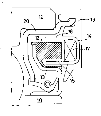
Let's now describe the device according to the invention
referring to the enclosed drawings , wherein:

` ` 2014049
.
Fig.1 to 5: these fig. show sections of a bearing and
relevant shield equipped with the device subject of the
invention in various possible configurations both of bearing
with shield and of the device;
Fig. 6 and 7: front views of the sensor adopted resp. by the
solutions of fig. 4 and 5;
~ig . 8,9 and 10 are resp. the expanded, front and side
views of a detail of the sensor of fig.1,2,and 3;
Fig.11 is the front view of the magnetized phonic ring of
fig.1,2 ,3,4 and 5;
Fig.1 to 5 show a detail of a bearing equipped with this
device in a few different configuration of this invention.
In fig. 2,3 and 5 outer ring 11 of the bearing rotates
while inner ring 10 is stationary. Vice versa, in fig.1 and
4 inner ring 10 rotates and outer ring 11 is stationary .
In all above mentioned configurations phonic ring 12 is made
of magnetized material according to the invention as
schematically illustrated by fig. 11 , that is with pairs
of magnetic poles of opposite polarity alternating in
variable number according to ring diameter and maker's
requirements.
Ring 12 is supported by a rigid profile 13, duly sized and
fixed to the rotating ring of the bearing, which , as
already described for the configurations of fig. 1 and 4
is inner ring 10, while for the configurations described by
fig.2,3 and 5 it is outer ring 11.
Facing ring 12 is the sen~or , various configurations of

201 4049
which- are possible and some fo which are shown by fig.6,7
,8,9 and 10.
The first configuration is shown by fig.8,9 and 10 where the
sensor has a ring 14, which, expanded, (fig.8) has inner
radial appendices 15 and outer radial appendices 16 folded
towards one side of the ring in the configuration shown by
fig. 9 and 10.
Ring 14 in this configuration will have an inner detecting
coil 17 (fig.1 to 3) and will be connected with a data-
processing on-board gsarc~se by means of a cable or a
connector 18.
For what ring 14 is still concerned, the tips of its outer
appendices 16 and inner appendices 15 will permit to close
an N number of sensor pole pieces , also variable, like the
pairs of magnetic poles with opposite polarity of rotating
ring 12.
Referring to fig.1 the ring is supported by a block 1~
engaged on the projected end of shield 10 of the bearing or
directly on the stationary ring of the bearing.
ln the configuration of fig.2 the ring is fixed by its inner
appendices 15 to shield 20. while in the configuration of
fig.3 ring 14 is integral with or welded to shield 20. in
all configurations, however, the sensor unit is inside the
shield, integral with it, therefore it does not feel any
variation of the brake disc temperature , is not exposed to
wear by metal particles frm the brake disc, is protected
against any outer polluting element and requires no prvious

')01 4049
calibration by the user. Even if the configuration of ring
14 shown in fig.8,9 and 19 seems to be the most advantageous
and reliable configuration, the ring can have other
configurations,too.
Por instance, outer fins 16 or inner fins 15 can be missing,
therefore the remaining fins 15 or 16 provide for closing
the pole pieces of the sensor.
Alternatively, again, outer fins 16 or inner fins 15 can be
replaced by a fold obtained on the ring perpendicular to the
ring face so that coil 17 is contained between two endless
surfaces (the face of the ring and the surface perpendicular
to it) and a row of fins 15 or 16.
The latter will close the pole pieces of the sensor, while
the endless surfaces will container both sensor and relevant
magnetic flux.
Should one of the rows 15 or 16 be replaced by an endless
surface , this could be advantageously be welded or be
integral with shield 20 making the unit even simpler and
more reliable.
In the configuration shown by fig. 6 and 7 ring 21 of the
sensor has radial appendices 22, either inner(fig. 6) or
outer (fig.7) equally spaced along the circumference and in
relation to the number of polar paiers of opposite sign of
the magnetized ring.
Moreover ring 21 bears windings 23 alternating between the
adjacent appendices 22 as illustrated in the figures.
~ig. 6 and 7 show four windings , but their number can vary
k

~ ~ 2014049
1 to n (wherein n is the numer of pole pairs divided per
two).
These appendices 22 , too are pole pieces of ring 21, whih
is mounted through a block 19 in the configurations shown in
fig. 4 and 6 , so as ring 14 of fig.1 was mounted; the ring
of fig. 5 and 7 is mounted directly on the appendix of
shield 20 of the bearing.
In this case, too the sensor is integral with the bearing
shield with the same advantages of the configuration
described above.
In the configurations of ring 21 , fi.6 and 7 , the rotating
ring 12 can be polarized radially through, like schematized
by fig.11 , but it can also be polarized on the outer side
(when used in the configuration of fig.4 and ~) or only on
the inner side (when used in the configuration of fig. 5 and
7) in that is is enough for the polarized surface to be met
at pole pieces 22 of ring 21.
Therefore, it appears that all configurations obtain a
passive, inducitve , flux-modulating sensor, with n pole
pieces integral with the bearing shield-
Being passive it requires no input; being inductive, flux-
modulating and with n pole pieces it permits to obtain a
signal which is directly compatible with the present
gearcases and highly reliable and precise.

Dessin représentatif
Une figure unique qui représente un dessin illustrant l'invention.
États administratifs

2024-08-01 : Dans le cadre de la transition vers les Brevets de nouvelle génération (BNG), la base de données sur les brevets canadiens (BDBC) contient désormais un Historique d'événement plus détaillé, qui reproduit le Journal des événements de notre nouvelle solution interne.

Veuillez noter que les événements débutant par « Inactive : » se réfèrent à des événements qui ne sont plus utilisés dans notre nouvelle solution interne.

Pour une meilleure compréhension de l'état de la demande ou brevet qui figure sur cette page, la rubrique Mise en garde , et les descriptions de Brevet , Historique d'événement , Taxes périodiques et Historique des paiements devraient être consultées.

Historique d'événement

Description Date
Le délai pour l'annulation est expiré 2006-04-06
Inactive : CIB de MCD 2006-03-11
Lettre envoyée 2005-04-06
Accordé par délivrance 1996-01-30
Exigences pour une requête d'examen - jugée conforme 1992-03-24
Toutes les exigences pour l'examen - jugée conforme 1992-03-24
Demande publiée (accessible au public) 1991-06-15

Historique d'abandonnement

Il n'y a pas d'historique d'abandonnement

Historique des taxes

Type de taxes Anniversaire Échéance Date payée
TM (brevet, 8e anniv.) - générale 1998-04-06 1998-03-18
TM (brevet, 9e anniv.) - générale 1999-04-06 1999-03-24
TM (brevet, 10e anniv.) - générale 2000-04-06 2000-03-20
TM (brevet, 11e anniv.) - générale 2001-04-06 2001-03-21
TM (brevet, 12e anniv.) - générale 2002-04-08 2002-03-20
TM (brevet, 13e anniv.) - générale 2003-04-07 2003-03-20
TM (brevet, 14e anniv.) - générale 2004-04-06 2004-03-22
Titulaires au dossier

Les titulaires actuels et antérieures au dossier sont affichés en ordre alphabétique.

Titulaires actuels au dossier
SKF INDUSTRIE S.P.A.
Titulaires antérieures au dossier
ANGELO VARVELLO
ANGELO VIGNOTTO
ROBERTO MORETTI
Les propriétaires antérieurs qui ne figurent pas dans la liste des « Propriétaires au dossier » apparaîtront dans d'autres documents au dossier.
Documents

Pour visionner les fichiers sélectionnés, entrer le code reCAPTCHA :


Pour visualiser une image, cliquer sur un lien dans la colonne description du document. Pour télécharger l'image (les images), cliquer l'une ou plusieurs cases à cocher dans la première colonne et ensuite cliquer sur le bouton "Télécharger sélection en format PDF (archive Zip)" ou le bouton "Télécharger sélection (en un fichier PDF fusionné)".

Liste des documents de brevet publiés et non publiés sur la BDBC .

Si vous avez des difficultés à accéder au contenu, veuillez communiquer avec le Centre de services à la clientèle au 1-866-997-1936, ou envoyer un courriel au Centre de service à la clientèle de l'OPIC.


Description du
Document 
Date
(aaaa-mm-jj) 
Nombre de pages   Taille de l'image (Ko) 
Page couverture 1994-01-29 1 18
Abrégé 1994-01-29 1 21
Revendications 1994-01-29 2 44
Description 1994-01-29 7 199
Dessins 1994-01-29 3 74
Page couverture 1996-01-30 1 21
Abrégé 1996-01-30 1 20
Description 1996-01-30 7 220
Revendications 1996-01-30 2 50
Dessins 1996-01-30 3 82
Dessin représentatif 1999-07-15 1 10
Avis concernant la taxe de maintien 2005-06-01 1 172
Taxes 1997-03-19 1 31
Taxes 1996-03-19 1 60
Taxes 1995-03-21 1 59
Taxes 1994-03-21 1 54
Taxes 1993-03-15 1 46
Taxes 1992-03-19 1 31
Courtoisie - Lettre du bureau 1992-04-22 1 45
Correspondance de la poursuite 1992-03-24 1 30
Courtoisie - Lettre du bureau 1993-11-30 1 14
Correspondance reliée au PCT 1995-11-28 1 32