Sélection de la langue

Search

Sommaire du brevet 2014142 

Énoncé de désistement de responsabilité concernant l'information provenant de tiers

Une partie des informations de ce site Web a été fournie par des sources externes. Le gouvernement du Canada n'assume aucune responsabilité concernant la précision, l'actualité ou la fiabilité des informations fournies par les sources externes. Les utilisateurs qui désirent employer cette information devraient consulter directement la source des informations. Le contenu fourni par les sources externes n'est pas assujetti aux exigences sur les langues officielles, la protection des renseignements personnels et l'accessibilité.

Disponibilité de l'Abrégé et des Revendications

L'apparition de différences dans le texte et l'image des Revendications et de l'Abrégé dépend du moment auquel le document est publié. Les textes des Revendications et de l'Abrégé sont affichés :

  • lorsque la demande peut être examinée par le public;
  • lorsque le brevet est émis (délivrance).
(12) Demande de brevet: (11) CA 2014142
(54) Titre français: FENETRE EN PROFILES EXTRUDES DE MATIERE PLASTIQUE
(54) Titre anglais: WINDOW ASSEMBLY OF EXTRUDED PLASTICS MATERIAL
Statut: Réputée abandonnée et au-delà du délai pour le rétablissement - en attente de la réponse à l’avis de communication rejetée
Données bibliographiques
(51) Classification internationale des brevets (CIB):
  • E06B 01/26 (2006.01)
  • E06B 03/44 (2006.01)
  • E06B 03/96 (2006.01)
(72) Inventeurs :
  • MORTON, PHILIP G. (Etats-Unis d'Amérique)
(73) Titulaires :
  • DAYTON EXTRUDED PLASTICS, INC.
  • ALUMINUM COMPANY OF AMERICA
(71) Demandeurs :
  • DAYTON EXTRUDED PLASTICS, INC. (Etats-Unis d'Amérique)
  • ALUMINUM COMPANY OF AMERICA (Etats-Unis d'Amérique)
(74) Agent: GOWLING WLG (CANADA) LLP
(74) Co-agent:
(45) Délivré:
(22) Date de dépôt: 1990-04-09
(41) Mise à la disponibilité du public: 1990-11-01
Licence disponible: S.O.
Cédé au domaine public: S.O.
(25) Langue des documents déposés: Anglais

Traité de coopération en matière de brevets (PCT): Non

(30) Données de priorité de la demande:
Numéro de la demande Pays / territoire Date
345,666 (Etats-Unis d'Amérique) 1989-05-01

Abrégés

Abrégé anglais


WINDOW ASSEMBLY OF EXTRUDED PLASTICS MATERIAL
Abstract of the Invention
A rectangular window frame includes vertical jamb members rigidly
connected by a head member and a sill member all formed from extrusions
of rigid plastics material or vinyl. The jamb members include outer
portions integrally connected to inner portions, and the outer portions
of the jamb members have welded mitered corner joints with the sill member
and the head member. The inner portions of the jamb members have right
angle end surfaces which abut the head and sill members to cover internal
flash at the corner joints. The sill member has a sloping top wall which
welds to internal walls of the jamb members, and the jamb and head members
have inwardly projecting flanges which engage one side of an insulated
glass unit retained by extruded glazing beads inserted into grooves within
the frame members and a cross rail at the middle of the frame. A lower
durometer or semi-rigid integral nailing flange projects outwardly from
a peripheral recess formed within the frame.

Revendications

Note : Les revendications sont présentées dans la langue officielle dans laquelle elles ont été soumises.


CLAIMS:
1. A window assembly adapted for use in a vertical wall of a building,
comprising a generally rectangular frame supporting a generally
rectangular light transmitting window unit, said frame including a pair
of elongated vertical jamb members connected by a horizontal head member
and a horizontal sill member, each of said members being formed from an
extrusion of rigid plastics material, each of said jamb members including
an outer portion integrally connected to an inner portion projecting
inwardly into the frame from said outer portion, said outer portions of
said jamb members having welded mitered corner joints with said sill
member and said head member, and said inner portions of said jamb members
having substantially right angle end surfaces abutting said horizontal
head member and sill member for covering internal flash of said welded
mitered corner joints.
2. A window assembly as defined in claim 1 wherein said inner portions
of said jamb members are hollow and include flange portions projecting
inwardly of said frame, and a generally rectangular screen unit engaging
said flange portions.
3. A window assembly as defined in claim 1 wherein said head member and
said jamb members have flange portions projecting inwardly of said frame,
means forming a weather-tight seal between said flange portions and a
peripheral portion of said window unit, said head member and said jamb
members having corresponding integral wall portions defining grooves
extending parallel to the corresponding said flange portions, and
elongated glazing members projecting into said grooves and cooperating
with said flange portions to confine said peripheral portion of said
window unit.

4. A window assembly as defined in claim 1 wherein said sill member
includes a top wall sloping downwardly at a slight angle, and said jamb
members include inner walls welded to said top wall of said sill member
at the lower said mitered corner joints.
5. A window assembly as defined in claim 1 wherein at least said jamb
members include outwardly projecting and integrally extruded co-planar
nailing flanges, and said nailing flanges have a lower durometer than the
durometer of said plastics material forming said jamb members to provide
for driving nails through said nailing flanges without splitting said
flanges.
6. A window assembly as defined in claim 5 wherein said jamb members
have generally flat outer walls defining longitudinally extending
recesses, and said nailing flanges connect with said jamb members within
said recesses to facilitate trimming at least one of said nailing flanges
from the corresponding said jamb member.
7. A window assembly as defined in claim 1 wherein said sill member
includes a sloping top wall defining a groove extending between said jamb
members, a generally rectangular screen unit seated within said groove,
and said end surfaces of said inner portions of said jamb members cover
the end portions of said groove.
8. A window assembly as defined in claim 1 wherein said jamb members
and said sill and head members have corresponding outer walls facing
outwardly of the building, and said outer walls are inclined relative to
the plane of said frame to form a frusto-pyramidal exterior surface on
said frame.

9. A window assembly adapted for use in a vertical wall of a building,
comprising a generally rectangular frame supporting a generally
rectangular light transmitting window unit, said frame including a pair
of elongated vertical jamb members connected by a horizontal head member
and a horizontal sill member, each of said members being formed from an
extrusion of rigid plastics material, each of said jamb members including
an outer portion integrally connected to an inner portion projecting
inwardly into the frame from said outer portion, said sill member
including a top wall sloping downwardly at a slight angle, said outer
portions of said jamb members having welded mitered corner joints with
said sill member and said head member, and said jamb members each having
an internal wall between said inner and outer portions and welded to said
top wall of said sill member at the lower said corner joints.
10. A window assembly as defined in claim 9 wherein at least said jamb
members include outwardly projecting and integrally extruded co-planar
nailing flanges, and said nailing flanges have a lower durometer than the
durometer of said plastics material forming said jamb members to provide
for driving nails through said nailing flanges without splitting said
flanges.
11. A window assembly as defined in claim 9 wherein said jamb members
have generally flat outer walls defining longitudinally extending
recesses, and integrally extruded co-planar nailing flanges project
outwardly from said recesses to facilitate trimming at least one of said
nailing flanges from the corresponding said jamb member.

12. A window assembly as defined in claim 9 wherein said sill member
includes a sloping top wall defining a groove extending between said jamb
members, a generally rectangular screen unit seated within said groove,
and said inner portions of said jamb members have substantially right
angle end surfaces covering the end portions of said groove.
13. A window assembly adapted for use in a vertical wall of a building,
comprising a generally rectangular frame supporting a generally
rectangular light transmitting window unit, said frame including a pair
of elongated vertical jamb members connected by a horizontal head member
and a horizontal sill member, each of said members being formed from an
extrusion of rigid plastics material, at least said jamb members including
outwardly projecting and integrally extruded co-planar nailing flanges,
and said nailing flanges have a lower durometer than the durometer of said
plastics material forming said jamb members to provide for driving nails
through said nailing flanges without splitting said flanges.
14. A window assembly as defined in claim 13 wherein said jamb members
have generally flat outer walls defining longitudinally extending
recesses, and said nailing flanges connect with said jamb members within
said recesses to facilitate trimming at least one of said nailing flanges
from the corresponding said jamb member.
11

15. A window assembly adapted for use in a vertical wall of a building,
comprising a generally rectangular frame supporting a generally
rectangular light transmitting window unit, said frame including a pair
of elongated vertical jamb members connected by a horizontal head member
and a horizontal sill member, each of said members being formed from an
extrusion of rigid plastics material, each of said jamb members including
an outer portion integrally connected to an inner portion projecting
inwardly into the frame from said outer portion, said outer portions of
said jamb members having mitered corner joints with said sill member and
said head member, means for rigidly connecting said members at said corner
joints, and said inner portions of said jamb members having substantially
right angle end surfaces abutting at least said horizontal sill member.
16. A window assembly as defined in claim 15 wherein said inner portions
of said jamb members are hollow and include flange portions projecting
inwardly of said frame, and a generally rectangular screen unit engaging
said flange portions.
17. A window assembly as defined in claim 15 wherein said head member
and said jamb members have flange portions projecting inwardly of said
frame, means forming a weather-tight seal between said flange portions and
a peripheral portion of said window unit, said head member and said jamb
members having corresponding integral wall portions defining grooves
extending parallel to the corresponding said flange portions, and
elongated glazing members projecting into said grooves and cooperating
with said flange portions to confine said peripheral portion of said
window unit.
12

18. A window assembly as defined in claim 15 wherein said sill member
includes a top wall sloping downwardly at a slight angle, and said jamb
members include inner walls mating with said top wall of said sill member
at the lower said mitered corner joints.
19. A window assembly as defined in claim 15 wherein at least said jamb
members include outwardly projecting and integrally extruded co-planar
nailing flanges, and said nailing flanges have a lower durometer than the
durometer of said plastics material forming said jamb members to provide
for driving nails through said nailing flanges without splitting said
flanges.
20. A window assembly as defined in claim 15 wherein said sill member
includes a sloping top wall defining a groove extending between said jamb
members, a generally rectangular screen unit seated within said groove,
and said end surfaces of said inner portions of said jamb members cover
the end portions of said groove.
13

Description

Note : Les descriptions sont présentées dans la langue officielle dans laquelle elles ont été soumises.


- 2014~2
Docket 5411
WINDOW ASSEMBLY OF EXTRUDED PLAS~ICS MA~ERIAL
Background of the In~çntion
In the construction of rigid vinyl window assemblies, for example,
of the type disclosed in U.S. Patents No. 4,259,813, No. 4,428,156, No.
4,555,868 and No. 4,580,356, the window and sash frames are formed of
sections of extruded rigid vinyl or similar plastics material. It has
been found desirable to form each of the frames with fusion-welded mitered
corner joints in place of mechanical fasteners in order tD provide a
fluid-tight frame with substantial rigidity and to avoid the possibility
of the fasteners becoming loose after a period of time or use.
One of the problems encountered with welded mitered corner joints
on the window and sash frames, is the creation of flash at the corner
joints. The external flash which projects outwardly from the frame
corners may be quickly and efficiently removed with the aid of a trimming
machine. However, the internal flash requires hand trimming which adds
significantly to the time and cost for producing a window frame with
welded mitered corner joints. It is also desirable for the sill member
of the window frame to have a slope for water drainage but without adding
on or attaching another sill section such as disclosed in above mentioned
Patent No. 4,580,366. The additional sill section not only adds costs to
the frame but also increases the overall height of the sill and thereby
reduces the height of the viewing area through the glass unit.
It has also been found desirable in new constructiDn for a vinyl
window frame to incorporate an integral nailing flange through which nails
may be driven without requiring a prepunched or drilled hole.
Furthermore, when the window assembly is combined with another window
assembly, it is frequently desirable to remove the opposing nàiling

- 2a~l42
Docket ~4 11
flanges so that the window assemblies may be installed in closely spaced
relation. One form of integrally formed or extruded nailing flange is
disclosed in above mentioned Patent No. 4,2599~13.
Summarv of the Invention
The present invention is directed to an improved rectangular window
assembly which may be of the vertical or horizontal sliding type and which
incorporates sections of extruded rigid plastics or vinyl material
assembled together to provide all of the desirable features mentioned
above. In accDrdance with one embodiment of the invention, a window
assembly incorpDrates a rectangular frame formed by a pair of elongated
vertical jamb members connected by a horizontal head member and a
horizontal sill member. Each of the members is formed from an extrusion
of rigid vinyl with each jamb member including an outer portion integrally
connected to an inner portion projecting inwardly into the frame from the
outer portion. The outer portions of the jamb members have welded mitered
corner joints with the sill member and the head member, and the inner
portions of the jamb members have right angled end surfaces abutting the
horizontal head member and sill member for covering internal flash at the
welded mitered corner joints.
The sill member includes a sloping top wall and a rib which are
welded to inner walls of the jamb members at the bottom mitered corner
joints. The window frame members also incorporate outwardly projecting
an integrally extruded semi-rigid nailing flanges which have a durometer
substantially lDwer than the durometer of the frame members so that nails
may be driven through the nailing flanges without splitting the flanges.
The nailing flanges project outwardly from slight recesses formed within
the outer walls of the frame members to provide for conveniently removing
any portion of the nailing flanges and obtaining a flush outer surface
without further trimming.

- 201~142
Docket 5411
Other features and advantages of the invention will be apparent from
the following description, the accompanying drawings and the appended
claims.
Brief Desc~iption of the Drawing
FIG. 1 is a perspective view of a single hung window assembly
constructed in accordance with the invention;
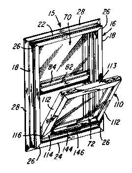
FIG. 2 is an elevational view of the outside of the window assembly
shown in FIG. 1;
FIG. 3 is a vertical section taken generally on the line 3-3 of FIG.
2;
FIG. 4 is a fragmentary horizontal section taken generally on the
line 4-4 of FIG. 2; and
FIG. 5 is a fragmentary horizontal section taken generally on the
line 5-5 of FIG. 2.
Description of the Preferred Embodiment
~he window assembly 15 illustrated in FIG. 1 includes a rigid window
frame 16 formed by a pair of rigid plastic or vinyl jamb members 18
connected by a rigid vinyl head member 22 and a rigid vinyl sill member
24. The elongated frame members 18, 22 and 24 are tubular or hollow and
are rigidly connected by fusion-welded mitered corner joints 26. Each of
the frame members 18, 22 and 24 is extruded from a vinyl material having
a durometer preferably between 105 and 110, and each of the frame members
also includes an outwardly projecting integral nailing flange 28 which is
extruded with a lower durometer, preferably between 80-95. ~his lower
durometer permits nails to be driven through the flange without requiring
prepunched or drilled holes within the flange. The integral nailing
flange 28 on each frame member connects to the frame member within a
.
,

- _ 201~142
Docket 5411
longitudinally extending groove or recess 31 which permits convenient
removal of the flange, as will be explained later.
Referring to FIG. 4, each of the hollow jamb members 1~ includes an
outer portion 36 and an integrally extruded inner portion 38 which has an
S inwardly projecting hollow flange 39. The outer portion 36 defines a
channel 42 and a pair of undercut grooves 44 for receiving trim
accessories (not shown), and has an angled exterior surface 46. An inner
wall 47 joins the outer portion 36 to the inner portion 38, and the inner
portion 38 also has a longitudinally extending undercut groove 48.~
As shown in FIG. 3, the tubular head member 22 also incorporates a
pair of undercut grooves 44 for receiving trim accessories, an inwardly
projecting hollow flange 49 and an angled exterior surface 51. The head
member 22 also has an inverted U-shaped wall portion which defines a
longitudinally extending undercut groove 53. As also shown in FIG. 3, the
sill member 24 includes an upwardly or inwardly projecting flange 56 with
a latch recess 57, a downwardly facing groove 44 for receiving trim
accessories and an angled exterior surface 59. In addition, the sill
member has a slightly inclined or sloping top wall 62 which extends to a
channel 63 partially defined by an upwardly or inwardly projecting rib
portion 66.
The window frame 16 encloses a stationary insulated glass unit 70
and a movable or vertically sliding insulated glass unit 72. Each of the
units 70 and 72 includes a pair of rectangular glass panels or lites 74
bonded together by a peripheral rubber-like adhesive strip 76 and
separated by a rigid rectangular spacer frame 78. The stationary
insulated glass unit 70 extends between the jamb members 18 and from the
head member 22 to a cross or meeting rail 82 which is also extruded of a
rigid plastics or vinyl material. The rail 82 has upwardly and downwardly
projecting hollow flanges 84 and is reinforced by an extruded aluminum
insert cross rail or member 86 having opposite end portions secured to
,, . . . ~ - .
. . .- . , , . . ~, , , .

--- 2014142
Docket 5411
the inner portions 38 of the jamb members 18 by a set of screws ~9 (FIG.
4). ~he stationary glass unit 70 is retained against the adjacent flanges
39, 49 and 84 by extruded rigid vinyl glazing beads or strips 92 which
snap fit into the grooves 48 and 53 and into a corresponding undercut
groove 94 (FIG. 3) formed within the meeting rail 82.
As shown in FIG. 2, the outer portions 36 of the jamb members 18
have fusion-welded mitered corner joints 26 with the head member 22 and
sill member 24. The inner portions 38 of the jamb members lB are cut with
right angle lower end surfaces 102 which abut the top surfaces of the wall
62 and rib 66 of the sill member 24. S;milarly, the jamb portions 38 have
right angle upper end surfaces 104 which abut the bottom surface of the
head member 22. The flange 49 has right angle end surfaces which abut the
flanges 39 on the jamb members 18. As a result, the inner portions 38 of
the jamb members 18 are effective to cover and hide the internal flash
which is produced during the welding operation of the mitered corner
joints 26.
Referring to FIGS. 3-5, the vertically movable or sliding window
unit 72 includes a sash frame 110 formed of extruded sections 112, 113 and
114 of rigid vinyl, and the sections have mitered corner jolnts 116 which
are fusion-welded or joined with mechanical fastening means. When the
extruded vinyl sections 112-114 are welded together around the assemble
glass panels 74, the window unit 72 has substantial rigidity, and
integrally extruded fins 119 provide a weather-tight seal between the sash
frame and the glass panels.
As shown in FIG. 1, the movable window unit 72 may be pivoted
inwardly to simplify cleaning of the glass panels 74. A set of pivot
members or channels 124 (FIG. 3) project outwardly from opposite ends of
the base section 114 of the sash frame 110 and connect with pivot shoes
127 ~FIG. 5) supported for vertically sliding movement within the channels
42 of the jamb members 18. The pivot shoes 127 connect with a
, . , , : .

- 201~1~2
Docket 5411
counterbalance mechanism 132 of the known type which incorporates a
torsion spring confined within a tube and having a depending helical
rotatable support rod connected to the corresponding pivot shoe 127.
Referring to FIG. 4, a set of tilt latches 136 are mounted on the
top section 113 of the sash frame 110 and include slidable spring-biased
latch elements 138 which project outwardly into the channels 42 for
retaining the window unit 72 in a vsrtical position within the frame 16.
When the latch elements 136 are retracted inwardly, the window unit 72 may
be tilted as shown in FIG. 1, and the rotation of the pivot channels 124
is effe~tive to expand the shoes 127 so that they clamp the jamb members
18 and prevent sliding of the shoes while the window unit 72 is tilted.
A lift handle 144 (FIG. 3) is extruded as an integral part of the
bottom section 114 of the sash frame 110, and the center portion of the
handle 144 retains a pivotal latch element 146 formed from an extrusion
of rigid vinyl. An expansion spring 148 normally urges the latch element
146 into the latch recess 57 and into hooking engagement w~th the ~lange
56 of the sill member 24. As shown in FIGS. 3 and 5, the sections 112-
114 of the sash frame 110 are extruded with undercut channels or grooves
for receiving weather stripping 152 which contacts the jamb members 36,
sill member 24 and the meeting rail 82 to form a weather-tight seal when
the window unit 72 is in its downward closed position, as shown in FIG.
3. A rectangular screen unit 155 (FIGS. 3 & 5) includes a screen mesh 156
within a frame 158 which seats in the channel 63 on resilient springs 159
and engages the flanges 39 and 84.
From the drawing of the above description, it is apparent that a
window assembly constructed in accordance with the present invention,
provides desirable features and advantages. As mentioned above, the
construction of the frame 16 with the welded mitered corner joints 26 and
the square end surfaces 102 and 104 on the jamb members 18, eliminates the
need for hand cleaning or trimming of the internal flash from the joints

-- `~ 2014142
Docket 5411
26 since the flash is covered by the jamb portions 38. As a result, the
time required for producing the frame 16 is significantly reduced. In
addition, the cross-section of the jamb members lB and the cross-section
of the sill member 24 provides for fusion-welding of the sloping sill wall
62 to the internal walls 47 of the jamb members 18 at the bottom corner
joints 26 to provide the frame 16 with maximum strength and rigidity. As
another feature, the semi-rigid nailing flange 28 provides for attachment
of the window assembly 15 with nails driven through the flange 28 without
requiring prepunched or dr111ed holes. The recess 31 at the base of each
nailing flange 28 also provides for conveniently trimming and removing the
nailing flange by scoring the flange with a sharp knife drawn along the
recess 31 so that no remaining portion of the severed nailing flange
projects outwardly from the outer surface of the corresponding frame
member. The angular exterior surfaces 46, 51 and 59 also provide the
window assembly with a pleasing appearance.
While the window assembly herein described constitutes a
preferred embodiment of the invention, it is to be understood that the
invention is not limited to this precise assembly, and that changes may
be made therein without departing from the scope and spirit ~bf the
invention as defined in the appended claims.
The invention having thus been described, the following is claimed:

Dessin représentatif
Une figure unique qui représente un dessin illustrant l'invention.
États administratifs

2024-08-01 : Dans le cadre de la transition vers les Brevets de nouvelle génération (BNG), la base de données sur les brevets canadiens (BDBC) contient désormais un Historique d'événement plus détaillé, qui reproduit le Journal des événements de notre nouvelle solution interne.

Veuillez noter que les événements débutant par « Inactive : » se réfèrent à des événements qui ne sont plus utilisés dans notre nouvelle solution interne.

Pour une meilleure compréhension de l'état de la demande ou brevet qui figure sur cette page, la rubrique Mise en garde , et les descriptions de Brevet , Historique d'événement , Taxes périodiques et Historique des paiements devraient être consultées.

Historique d'événement

Description Date
Inactive : CIB de MCD 2006-03-11
Le délai pour l'annulation est expiré 1993-10-11
Demande non rétablie avant l'échéance 1993-10-11
Réputée abandonnée - omission de répondre à un avis sur les taxes pour le maintien en état 1993-04-09
Inactive : Demande ad hoc documentée 1993-04-09
Demande publiée (accessible au public) 1990-11-01

Historique d'abandonnement

Date d'abandonnement Raison Date de rétablissement
1993-04-09
Titulaires au dossier

Les titulaires actuels et antérieures au dossier sont affichés en ordre alphabétique.

Titulaires actuels au dossier
DAYTON EXTRUDED PLASTICS, INC.
ALUMINUM COMPANY OF AMERICA
Titulaires antérieures au dossier
PHILIP G. MORTON
Les propriétaires antérieurs qui ne figurent pas dans la liste des « Propriétaires au dossier » apparaîtront dans d'autres documents au dossier.
Documents

Pour visionner les fichiers sélectionnés, entrer le code reCAPTCHA :


Pour visualiser une image, cliquer sur un lien dans la colonne description du document. Pour télécharger l'image (les images), cliquer l'une ou plusieurs cases à cocher dans la première colonne et ensuite cliquer sur le bouton "Télécharger sélection en format PDF (archive Zip)" ou le bouton "Télécharger sélection (en un fichier PDF fusionné)".

Liste des documents de brevet publiés et non publiés sur la BDBC .

Si vous avez des difficultés à accéder au contenu, veuillez communiquer avec le Centre de services à la clientèle au 1-866-997-1936, ou envoyer un courriel au Centre de service à la clientèle de l'OPIC.


Description du
Document 
Date
(aaaa-mm-jj) 
Nombre de pages   Taille de l'image (Ko) 
Revendications 1990-10-31 6 187
Abrégé 1990-10-31 1 23
Dessins 1990-10-31 1 70
Description 1990-10-31 7 260
Dessin représentatif 1999-07-28 1 22
Taxes 1992-03-25 1 38