Note : Les descriptions sont présentées dans la langue officielle dans laquelle elles ont été soumises.
2~ 44~
TWO STAGE AIR FILTRATION SYSTEN
Backqround of the Invention
The present invention relates generally to a two stage air
filtration system for removing relatively large particles of materials
entrained in an air stream, such as a system used in textile
processing environments where large particles of waste material are
generated by the textile processing equipment and carried away in an
air stream.
As is well known in the textile field, various operations
included in textile processing inherently tend to generate textile
waste materials which vary from fine dust to relatively large
particles of waste. It is common practice ~o operate large numbers
of textile processing machines in the same general area, such as
carding machines in a carding room, each of which is usually
individually connected to a central waste collection system that
utilizes large volumes of air flow to entrain the waste generated by
the machines and carry it away from the machines. Additionally, it
ie common practice to recirculate the air within a textile processing
area for the purpose of removing waste therefrom that could be
hazardous to personnel working in the area and that could adversely
affect the operation of the textile operating equipment.
Additionally, this recirculated air must be ~conditioned~ to provide
the proper operating environment for the textile machines and the
textile materials being processed, such as maintaining the temperature
and humidity of the recirculated air within predetermined ranges using
conventional air conditioning equipment designed for this purpose.
In many textile mills, systems typically utilize large
volumes of air (e.g. 50,000 c.f.m.) to entrain and carry away the
wa~te as discussed above, and this air with entrained waste is
';''' '. ':
Q~
transported through conduits to equipment designed to remove the waste
from the air and return at least most of the cleaned air back to the
textile processing area.
One commonly employed system used for this purpose is a two
stage system that includes a first stage preseparator having a large
cylindrical filter element disposed in a housing, and the air to be
cleaned is introduced at the inside surface of the cylindrical filter
in a direction generally tangential there~o, whereby the large waste
particles in the air are removed by the filter as the air flows
outwardly therethrough. These large waste particles fall to the
bottom of the filter and are collected there, but the air passing
through the filter, which is relatively porous, still has some fine
dust entrained therein. Roughly ninety-five percent of the incoming
air passes through the filter and it is then caused to flow through
a panel filter, such as a panel filter of the type disclosed in U.S.
Patent No. 4,725,292 which xemoves essentially all of the fine dust
from the air. This cleaned air is then returned directly to the main
air recirculation system, and it is to be noted that this returned air
i~ still "conditioned,t~ at least partially, so that it does not
require nearly as much ~conditioning~ as would drawing in ambient air
from the outside, thereby rendering the system more efficient. The
other roughly five percent of the original air is directed away from
the upstream ~ide of the cylindrical filter to carry with it the
afore~aid relatively large waste particles collected by the filter,
and thi8 8mall quantity of air is introduced into a second stage
filter, or fiber extractor, such as the device disclosed in U.S.
Patent No. 4,502,874. As explained in greater detail in the patent,
fiber extractors of this type are designed for continuous operation
and, consequently, they are large so as to include two duplicate flow
paths for the air to be cleaned and valves operated by sensors for
alternately directing the air through one flow path while the other
flow path -is taken off line and the filter is cleaned of collected
waste particles, which are then allowed to drop from the housing of
the fiber extractor. The cleaned air is then generally discharged to
the atmosphere.
Nhile two stage filtration systems of the foregoing type are
generally satisfactory, they suffer two significant drawbacks. First,
the fiber extractor itself, because it is designed for continuous
operation, is relatively expensive to produce and operate primarily
because of the large housing required to provide the necessary
alternate flow paths for the air, and the control elements required
to maintain the equipment in continuous operation. Secondly, in known
systems using such fiber extractors, the large quantities of waste
removed from the air is appropriately processed for disposal, such as
by dumping it into a baling machine, but the cleaned air is exhausted
into the atmosphere and any residual ~conditioning~ of such air (e.g.
temperature and humidity levels) are lost. Therefore, make up air for
replacing this exhausted air in the general textile environment must
be drawn in from the atmosphere and passed through conditioning
equipment, all of which increases the capital and operating expenses
of the system as a whole because larger capacity conditioning
equipment must be provided and operated.
Another known two stage filtration system employs a
pre8eparator of the same general type as that described above, and,
instead of using a fiber extractor, the small quantity of air that is
diverted with the large particles of waste material is conducted
.4404
through a conduit from the upstream side of the cylindrical filter of
the preseparator to the inlet side of a conventional condenser. As
is well known in the art, these conventional condensers include a
filter screen that has a cylindrical configuration and that is rotated
about its axis by a motor so that relatively large waste particles
entrained in the input air stream collect on the surface of the
rotating screen as a mat, and this mat is doffed or peeled off of the
rotating screen by a stationary doctor blade for subsequent removal
from the condenser. In this system, the cleaned air is returned to
the preseparator at a point downstream of the filter thereof and
recombined with the main flow of air through such filter for further
processing by the panel filters as described above.
While the cleaned air is not lost to atmosphere as is the
case in systems of the first type described above, this second system
has its own drawbacks resulting from the use of condensers.
Condensers are relatively expensive to make and operate, particularly
because of the fact that it includes a rotating filter screen and
because of the tolerances required to direct the air flow properly
through the moving filter and to properly doff the mat from the
rotating filter screen. Moreover, for much the same reasons,
condensers tend to be somewhat undependable over long periods of
continuous operation. Finally, condensers have relatively large
operating costs re~ulting from the motor that is required to rotate
the filter 8creen and from relatively large pressure drop (e.g. a
maximum of about five inches of water) across the rotating filter
which requires large blowers to move the air through the rotating
filter.
By contrast, the two stage air filtration system of the
29~.44~
present invention provides a system that is less expensive to
fabricate and less expensive to operate, and/or that is more
dependable in operation because of the simplicity of its design and
operating characteristics.
Summary of the Invention
In accordance with the present invention, a filter system
is provided for removing textile waste materials and the like
entrained in a flow of transport air, such system including a first
stage air separator for initially separating large particles of the
waste materials from the air flow, and a second stage air filter for
additionally separating and collecting such large particles of waste
material. The first stage air separator includes a first filter ~ -
having a permeability for preventing the passage therethrough of large
particles of waste material, an air inlet for receiving the transport
air flow and directing it through the filter, a collector located at -
the upstream side of the filter for collecting the large particles of
waste material, and an outlet located downstream of the filter for
exhaustinq air after it has passed through the filter. The second
stage air filter includes a housing having a generally flat second
filter extending thereacross to divide the housing into an inlet
portion located below the second filter and an outlet portion located
above such filter, a first conduit that intexconnects the collector
portion of the first stage and the inlet portion of the second stage
housing, and a second conduit in~erconnecting the outlet portion of
the housing with the air outlet of the first stage separator. A
blower is provided for causing a predetermined small portion of the
air flow and the collected particles of waste in the first stage to
flow from the collection portion of the first stage through the first
' ~ ': ':'
" ', . '
2~
conduit, then through the second filter to separate the waste material
from the air flow, and then causing the cleaned air to flow back into
the air outlet of the first stage to be combined with the air flow
that has passed through the first stage filter. Also, the second
stage filter includes an arrangement for periodically removing the
large particles of waste material that collect in the inlet portion
of the second stage housing.
In the preferred embodiment of the present invention, the
housing of the second stage filter is comprised of a generally
rectangular enclosure with the flat filter extending generally
diagonally thereacross, and the housing includes a movable bottom wall
disposed beneath the filter and a selectively operable device for
moving the movable wall portion between a first position completing
the enclosure of the housing and collecting the large waste particles
thereon, and a second position providing an opening in said housing
to permit removal of the large waste particles. To assist in
separating the waste paxticles from the filter, a conduit may be
provided in the upper or outlet portion of the housing so as to extend
along the length of the filter, and this conduit includes a plurality
of openings directed toward the filter so that compressed air can be
introduced into the conduit to produce a burst of compressed air from
each of the openings in the conduit directed toward the filter so as
to pass through the filter and remove any waste particles clinging to
the bottom or inlet side of the filter.
Also, in the preferred embodiment of the present invention,
a valve is positioned in each of the first and second conduits of the
second 8tage filter, such valves being normally opened during
operation of the apparatus and being selectively clo~ed to isolate the
z~44~t4
filter of the second stage from its blower during cleaning of the
filter element and removal of the waste particles from the housing as
described above. In this regard, the present invention includes a
control, preferably in the form of a central processinq unit (CPU),
which establishes a cleaning cycle for the second stage filter by
operating, in sequence, to first stop the blower and close the valves
in the first and second conduits, th0n to cause the source of
compressed air to flow into the conduit in the housing to clean the
second filter, then energize the operating means for the movable wall
portion of the housing to remove waste particles therefrom, then
energize the operating means to close the movable wall, and then
reopen the valves in the first and second conduits and restart the
blower. ~-~
Brief De~cription of the Drawin~s
.
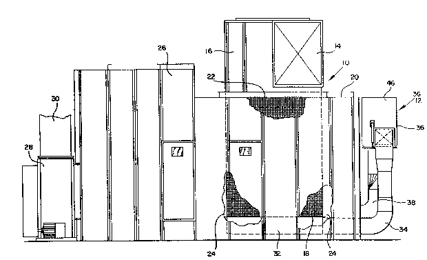
Fig. 1 is a side elevation view illustratinq the two stage
air filtration system of the present invention;
Fig. 2 is an end view of the system illustrated in Fig. 1;
Fig. 3 is a plan view of the system illustrated in Fig. 1;
Fig. 4 is a detailed side elevational view, partly in
section, illustrating the filter housing of the second stage filter;
Fig. 5A is a diagrammatic illustration of the control
circuit for the second stage filter; and
Fig. 5B is a diagram illustrating the sequence of operation -
of variou8 components included in the second stage filter.
De w ription of the Preferr~d Embodiment
Looking now in greater detail at the accompanying drawings,
Fig~ 3 illustrate the air filtration system of the present
invention which includes a first stage air separator, generally
'',' '.':~
: ' . ' ':
. '
' ....
~.44(~
indicated by the reference numeral 10, and a second stage air filter,
generally indicated by the reference numeral 12.
The first stage 10 includes a large inlet duct 14 arranged
to introduce a flow of air with waste materials entrained therein to
a generally cylindrical inlet compartment 16, the inlet duct 14 being
arranged to cause the air to flow into the inle~ chamber 16 generally
tangentially thereto so that the air flows around the walls of the
inlet chamber in a generally circular flow pattern. The inlet
compartment 16 is located above and coaxially with a large cylindrical
filter screen 18 which divides the first stage housing 20 into an
upstream or inlet portion 22 on the inside of the cylindrical filter
18, and an outlet portion at the downstream side of the filter 18 and
defined by the enclosure of the housing 20. The outlet portion 24 is
in open communication with a large panel filter 26, which is
preferably a panel filter of the type described in detail in U.S.
Patent No. 4,725,292, and a large fan 28 is provided for continuously
circulating large quantities of the transport air through the entire
system, the fan 28 having an outlet 30 through which cleaned air is
directed back into the main air flow system. In a typical application
of the present invention, the inlet duct 14 will receive transport air
from a plurality of textile processing machines, such as carding
machines as described above, and this transport air will have
entrained therein a substantial amount of waste material, both in the
form of large particles of waste material, fine dust, and other
foreign matter. The system fan 28 draws this transport air through
the large cylindrical filter 18, from the upstream or in~ide surface
thereof to the downstream or outside surface thereof, and the large
waste particles in the air, which constitute approximately ninety-
:~Q~
nine percent by weight of all o~ the waste material~, are separatedfrom the air by the cylindrical filter 18 which has a permeability
designed for this purpose, and the separated waste material at the
inæide of the cylindrical filter 18 falls by gravity and under the
influence of the swirling transport air into a collection compartment
32 located immediately below the filter 18. The air which is passed
through the filter 18 still contains some fine dust and similar
foreign matter which is removed therefrom as ~uch air passes through
the panel filter 26. The thus clean air exits through the fan outlet
30 where it is returned to the main air system of the textile
processing operation, which will usually include pa~sing the air
through conventional conditioning operations. However, it is to be
noted that the air which is returned to the main system is the same
air that was withdrawn from the textile processing environment, such
as from carding machines, and therefore this air still retains much
of the desired humidity and temperature conditioning which it had
before it was withdrawn for cleaning.
The second stage filter 12 is provided for efficiently
removing the large particles of waste material collected in the
collection compartment 32, and includes a first inlet conduit 34
extending from the collection compartment 32 to a filter unit 36 and
an outlet conduit 38 that extends from the filter unit 36 back to the
housing 20 of the first stage in open communication with the outlet
portion 24 of the first stage. Flap valves 40 and 42 are located in
the inlet and outlet conduits 34 and 36, respectively, such valves
being normally opened and selectively closed by a conventional
pneumatic cylinder controlled by an electrically actuated solenoid
valve in a manner to be described presently. Also, a fan 44, which
';;,:.
: :.
is much smaller than the system fan 28 described above, is located in
the outlet conduit 38 for moving air through the second stage.
As shown in greater detail in Fig. 4, the filter unit 36
includes a generally rectangular housing 46 having a flat filter
element 48 mounted on wall brackets 50 to extend angularly or
generally diagonally across the interior of the housing 46 to divide
it into an inlet chamber 52 located beneath the filter element 48 and
in communication with the inlet conduit 34, and an outlet chamber 54
located above the filter element 48 and in communication with the
outlet conduit 38. A pipe 56 is located in the outlet chamber 54 and
extends along the upper corner of the housing 46 and generally along
the length of the filter element 48, the pipe 56 being provided with
a plurality of sized apertures or openings 58 located in a direction
facing approximately the midpoint of the filter element 48. The pipe
56 is connected to any convenient source of compressed air (not shown)
which may be introduced into the pipe 56 in pulses of high pressure
air that exit through the openings 58 to direct bursts of air toward
the filter element 48 and in a direction opposite to the normal flow
of air through the filter element 48, such pulses acting to assist in
cleaning the filter element 48 by dislodging particles of waste
material collected on the upstream or lower face of the filter element
48 80 that such particles will fall by gravity to the bottom wall 60
of the housing 46. As best seen in Fig. 4, the bottom wall 60 is
mounted at one of its ends to a pivot connection 62, and one or more
conventional pneumatic operating cylinders 64 are mounted on the
exterior walls of the housing 46 with the piston 66 of each pneumatic
cylinder 64 being connected directly to the bottom wall 60 for moving
it between a normally closed position, shown in full lines in Fig. 4,
at which it completes the enclosure of the housing 46 by resting
against a seal 68, and an opened position, as shown in dotted lines
in Fig. 4, whereby waste materials collected in the housing 46 are
dumped automatically therefrom.
In a typical operation of the two stage filtering system of
the present invention, the system fan 28 is designed to circulate
approxLmately 50,000 c.m.f. of air, with entrained waste particles,
through the first stage 10. The smaller fan 44 in the second stage
is selected to draw off approximately five percent of the total air
being circulated through the first stage, and it is this five percent
which circulates through the second stage 12 with the waste materials
in the collection compartment 32. This relatively small air flow
passes through the filter unit 36 so that the large waste particles
carried from the collection compartment 32 are collected on the lower
or upstream ~urface of the filter element 48, and the cleaned air is
then reintroduced into the outlet portion 24 of the first stage
housing 20, at which point it is recombined with the main air flow
through the first stage and carried to the panel filter 26 for further
.. ..
cleaning as described above.
The air flowing upwardly within the housing 46 will result
in entrained waste materials being deposited on the bottom surface of
the filter element 46 as described above, and this air flow will tend
to hold the waste materials in place on the surface of the filter
rather than allowing the waste materials to fall to the bottom wall
60. Accordingly, in accordance with a further feature of the pre~ent
invention, a control ~ystem is provided for periodically cleaning the
filter element 48, such control system being diagrammatically
illu~trated in Fig~. 5A and 5B. As shown in Fig. 5A, a programmable
',. '' ~ '
.. .: . .
~5.
12
CPU 70 is provided to operate and control a conventional motor 72 for
the blower 44, solenoids 74 for the two valves 40 and 42, a solenoid
76 for operating the pneumatic cylinder 64 which pivots the movable
bottom wall 60, and a compressed air source 78 which provides pulses
of compressed air to the compressed air pipe 56.
As shown in Fig. 5B, the CPU 70 operates the aforesaid
components connected thereto in a predetermined sequence. When a
cleaning cycle begins (the 0 second point in Fig. SB), which may be
determined on a tLmed basis or when the pressure drop across the
filter element 48 reaches a predetermined maximum, the motor 72 of the
fan 44 is de-energized and the solenoids 74 for both of the valves 40
and 42 are operated to close such valves, so that the filter unit 36
is isolated from the fan 44 and no air flows upwardly through the
filter element 48 in a manner that would hold the waste material
thereagainst as descriibed above. Two seconds later, the compressed
air source 78 is energized for a very short period of time 80 that a
pulse of air is generated through each of the opening~ 58 in the pipe
56 to dislodge waste materials from the bottom surface of the filter
element 48, whereupon the dislodged waste particles fall to the bottom
wall 60. At the 4 second time interval, the solenoid 76 is operated
to cause the operating pneumatic cylinder 64 to pivot the movable ;
wall 60 to its open position, and the lower wall is perimitted to
remain at its open position for approximately six seconds during which
all of the waste material collected thereon falls from the housing 46
for collection in any convenient manner, such as collection in a
baling machine (not shown) or for manual collection after the waste
material is deposited on the floor. The bottom wall 60 is then closed
by the solenoid 76 for the operating cylinder 64, and a few seconds
. -. .
t
13
later the solenoids 74 are operated, and the valves 40 and 42 are
closed, after which the fan motor 72 ig re-energized to start the fan
44 to complete the cycle, all as shown in Fig. 5B.
It is to be understood, of course, that the foregoing
example is merely illustrative of one typical application of the
present invention, and that the present invention is not limited in
any way to this particular operation, which can be varied extensively
to adapt the system to other applications without department from the
scope of the present invention.
It will be apparent from the foregoing description that the
present invention provides substantial advantages as compared with the
~imilar systems which are presently known, as described above. More
specifically, the simplicity of the construction and operation of the
filter unit 36 results in a substantial savings in capital costs and
power consumption when compared to either the known fiber extractor
~ystem or the known condenser system used as second stages. In terms
of capital costs, it is believed that the present invention represents
a savings of approximately fifty percent in terms of the overall costs
of the filter unit 36 as compared to a fiber extractor, and a cost of
approximately one-third of the cost of a condenser. Moreover, the
filter unit 36 is considerably more dependable than a condenser
..-
because it includes only one moving part, namely the pivoted wall 60
:. . .
which i8 easy to construct and easy to operate, and it is cleaned by
simply isolating the filter unit 36 and removing the collected waste ~ -
materials from the bottom wall 60. In this same regard, the diagonal
or angular positioning of the flat filter element 48, with or without
the compressed air pipe 56, assists in causing the waste materials to
fall therefrom, which is a significant advantage as compared with the
,
..
"" : ', -,
~` ' ~
14
known fiber extractor described above. Finally, the filter unit 36
operates at a substantially reduced pressure drop, as compared to a
condenser, which results in significant energy savings, and these
energy savings are compounded by the fact that the drive motor
required for rotating the screen filter in a condenser is eliminated
in the present invention.
It will therefore be readily understood by those persons
skilled in the art that the present invention is susceptible of a
broad utility and application. Many embodiments and adaptations of
the present invention other than those herein described, as well as
many variations, modifications and equivalent arrangements will be
apparent from or reasonably suggested by the present invention and the
foregoing description thereof, without departing from the substance
or scope of the present invention. Accordingly, while the present
invention has been described herein in detail in relation to its
preferred embodiment, it is to be understood that this disclosure is
only illustrative and exemplary of the present invention and is made
merely for purposes of providing a full and enabling disclosure of the
invention. The foregoing disclosure is not intended or to be
construed to li~it the present invention or otherwise to exclude any
such other embodiment, adaptations, variations, modifications and
equivalent arrangements, the present invention being limited only by
the claims appended hereto and the equivalent~ thereof.