Note : Les descriptions sont présentées dans la langue officielle dans laquelle elles ont été soumises.
201~08
~e ~ d
7i Cc~ e,y~, )
M&C FOLIO: 180P 60697 WANGDOC 1522P ,.-
"Apparatu~ and method for blow-mouldln~ a hollow bodY~
The present inventlon relatas to apparatus and a
method for blow-moulding a hollow body of thermoplaatic~
material.
It 18 known to form an outwardly-extending annular
flange on the peripheral wall of a hollow body by means
of a blow mould having an annular rece~ in a peripheral
area. Material blow-moulded into the annular recess i8
squeezed together to form a solid rlng by moving
togethar a ~lidable mould part in the axial direction of
the mould toward~ a ~tationary middle part of the mould
after blow-moulding procedure.
Thé invention is not restricted only to axially
~ymmetrical hollow bodies (barrels), but also relates to
parallelepipedal bollow bodie~ such as for example
canisters or bottle-like containers w~th a rectangular
or square oros~-sectlon for example.
In the case of olosed hollow bodies, for example
bung-hole barrels, the flange rings moulded out of the
wall of the ! hollow body ln the blow mould are usad a~
rolllng hoops or carrying ring3. I~ th~ ca6e of
parallelepipedal hollow bodies, the closed flange
: , , , :
` . ' ' ' ' ', ' ' ~ ' '
.': ~ , ', ,:
'. : ' ' ' ~ '' `" ' ~ '' '
2Q15~8~
2 .
projections moulded out of the wall of the holl~w~ bodies
are also used as wall relnforcements.
In the case of pla3tics-material barrels, so-called
wide-necked barrels, which are closable by
plastics-material covers and which are generally taken
to mearl large-volu~e containers or barrels (of 220 lltre
storage capacity for example) with a filling opening or
a cover which is essentially equal ln size to the
diameter of the barrel, the flange ring likewise
comprises a squeezed shell flange which, in accordance
with German Patent No. 25 44 491, is arranged at a
distance below the barrel openlng and against which the
edge of the cover turned up onto the opening neck of the
barrel re~t~. The edge flange of the cover ¢orresponds
in its radial extension to the shell flange of the
barrel and tran~mits sta¢king forces in the axial
dire¢tion into the wall of the barrel. In the closed
position the ¢over ia se¢ured to the barrel by a
ten6ioned clamping ring angaglng over the c~ver edge on
one side and engaging under the shell flange on the
other side. In order to ensure a high degree of
sta¢kability of the barrels, the cover consists of hard
plastics material as a separately produced
1n~ectioL-mou1ded oomponent.
.~ . .,,, ~ . :
, ~ .
'". ~ ' : ' ' - : ~ :
, ,
~0~08~
Plastics-~aterial covers for barrels ars usu~lly
pre-fabricated as injection-moulded components in a
separate operatlng procedure. Apart from a separat~
in~ecting-mouldlng production proce~s, speclal
injection-moulding tool3 are therefore also required.
Edge flanges on plastics-material barrels can be
produced in various ways. Thus lt i8 known for example
to in~ert a pre-fabricated edge flangs a~ a ~eparate
in~ection-moulded component lnto a blow mould, in which
case this edge flange i8 welded to the outer wall of the
barrel during the production process or blow-moulding of
the barrel.
An objeot of the present invention i~ to make it
possible to produce the hollow body and the cover in one
blow-moulding operation.
The invention provides apparatus for blow-moulding
a hollow body of thermoplastics material comprising a
stationary mould part and first and second slidable
annular mould part~ defining two spaced annular recesse~
therebetween for producing two axially-spaced,
outwardly-extending peripheral flanges of the hollow
body, thereby allowing formation of a hollow body with
an annular flange and a cover with an annular flange in
a single blow-moulding operation.
.
: . . : .,: . . . . . . ~:
:'`- ,. '. . :. , , . ?
-;~: . . : :. ,
. ;
201508~
As a result a barrel and a cover may be formed in a
single blow mould with a ~o-called tandem slide, as a
resu~t of whlch production i8 ub~tantially shortened
and is les6 expen lve. Addltlonal outlay on maahlnes
and tool~ is unnecessary.
The lnvention also provides a method of forming a
hollow body of thermopla~tlc materlal uslng the above
~pparatus according to the lnventlon and comprising
blow-mouldlng a tube of thermoplastlcs material lnto the
apparatus,` moving the slidable annular mould part~ to
sgueezs the material in the annular rece~se~ to form a
respective annular body flange and an annular cover
flange therein, and separatlng the cover from the body
after moulding.
: When the blow-moulding procedure is completed the
hollow body is removed ~rom the mould, and it is merely
; necessary to ~eparate the cover from the body, or for an
annular lost connecting ring to be removed, ln order to
separate the body and the cover.
An embodiment o~ the lnventlon i8 illustrated by
way of example ln the accompanying drawingY, in which '~.
;' ' `' .
,, . ~
.
, :
:.~< . - ~ . ~ . ,
. -. : ... . .~ . . . .. .. -... . .
20~8~
Fig. 1 shows in axial section an end portion- of a
blow mould with the slide~ open and ths plastics tube
blow-mould~d;
Fig. 2 show~ th~ end portion of Fig. 1 wlth the
slide~ moving in the direction of the mould axls;
Fig. 3 ~hows the end portion of Fig. 1 wlth the
~lide~ closed, and
Fig. 4 shows in axial section the end of a barrel
after removal from the blow mould.
For reasons of clarity only the relevant portion of
the mould has been ~hown in the drawing~.
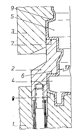
In Fig. 1 a blow mould compri~e~ an annular
slidable mould part or slide 2 arranged ln between an
annular slidable mould part or slide 1 and a stat$onary
mould part 3. The annular slide 2 ls diaplaceable in
the axial direction of the mould in the mould slide 1 on
one side and in the stationary mould part 3 on the other
side.
'`
When the mould is open, as ~hown in Fig. 1, a
blow-moulded, heated pla~tlcs tube 13 rest~ against the
internal contours of the mould. A flrst annular recess
4 i8 defined by-the end face 6 of the a~nular 61ide 2
? ~
: ~; , , , . -::
: ~ . ,: : -: . : . ,. :
:: :
201~084
and an end face 8 of the mould slide 1. The end ~ace 7
of the annular slide 2 and the end face 9 o~ the
stationary mould part 3 define a second annular recess
5. Peripheral walls of the corresponding mould parts 2,
3 define the radial extent of the annular recesfieS 4 and
5.
In the still weldable heated ~tate of tha ad~acent
tube 13, the mould slide 1 and the annular ~llde 2 move
axially in the direction toward~ the stationary mould
part 3. The axlal veloalty of the annular gllde 2 1B
less than, and it~ axial path is shorter than, the axial
velocity and the axial path of the mould slide 1,
~ respectively.
i Fig. 2 ~hows the blow mould in a condition in which
the displaceable mould parts 1 and 2 have covered
approximately half the closure path in the dlreation of
the arrows. Only the tube materlal present in the
annular recesses 4 and 5 is sgueezed together, until it
i8 welded together to form solid flange rings 14 and 15
l~ig. 4) in accordance with the end closed position
shown in Fig. 3. The movable mould parts 1 and 2 reach
thi~ end position at the same time.
Fig. 4 shows the end portion of the barrel removed
from the mould and turned through 180- i.e. similar to
Fig. 3 inverted; It should be added that the entire
.
,. ~, ' ,.
,. . ,, :
- . . . , , .: . .
2~1508~
mould i~ dlvlded ln the longitudlnal dlrection to form
two mould halve movabla ln a direction at right angle~
to the longitudinal axi~ of the barrel batween an open
and a closed po3 i ti on.
As can be 6een from Flgs. 3 and 4, the barrel 11
and cover 10 are connected by means of an intermediate
annular portion 12. This annular portion 12 between the
barrel 11 and the cover 10 acts as an annular "lo~t"
connecting ring and iB removed, so that the barrel 11
and the covar 10 become independent parts. The annular
portion 12 to be removed has not been hatched in Fig. 4,
so a~ to indicate its extent more clearly.
~ he blow mould may, however, be constructed in such
a way that the intermedlate annular portion 12 is
omitted. The main featuxe of the barrel accordlng to
the inventlon is that the harrel and the aover aonsist
of the same pla~tics material (having been produced from
the same blow-moulded plastic~ tube and having the same
fibre grain) and thu~ also have the same colour.
:,: : ~ . : -
~,:: . : . : , . : : , :
: , . .... : .
:: . . : . - : . . - :
:- . ~ . , . . . - . : -
,: . . . . . . .
,