Note : Les descriptions sont présentées dans la langue officielle dans laquelle elles ont été soumises.
20i~232
Envelope Transporting, AliQninQ and stacking Module
Background of the Invention
The instant invention relates to a modular device for
transporting, aligning and stacking envelopes, and more
particularly to such a device which can be combined with
other like devices to provide any desired length of
transport path and any desired number of stacking bins.
In high volume mailing applications, a plurality of
documents are fed from document feeding devices to a
location where they are inserted into an envelope. The
envelopes are then transported seriatim from the document
inserting position to another location for further
processing, which typically includes the printing of
postage on the envelopes. In many applications, it is
desirable to separate the output of the inserter by
diverting certain envelopes from the mainstream, or by
directing certain envelopes, such as all those having the
same zip code, to a designated collecting bin. When the
objective is to print postage on the envelopes downstream
of the inserting apparatus, it is necessary not only to
transport the envelopes from the inserting apparatus to the
postage meter or other printing device employed, but also
to align the envelopes so that the printing occurs
uniformly at the proper location on the envelopes.
There are available today various modules to perform
each of the processes described hereinabove, i.e.
transporting, aligning, diverting and stacking. These
modules are situated at an appropriate location in the
envelope path and perform their function as required.
However, there is no single module available today which
can be used to perform all of these tasks. Such a module
-2-
obviously would provide significant cost savings to both the
producer of the module and to the end user who would be able
to simply purchase a plurality of similar modules and then
deploy them as he saw fit.
Accordingly, the instant invention comprises a single
module to be used in the envelope transport path which can
be set up in a variety of formats and modified in order to
perform the functions of transporting the envelopes,
aligning the envelopes, stacking the envelopes and
deflecting the envelopes out of the envelope path, all at a
speed which does not slow down the inserting apparatus or
the postage meter or other printing apparatus used to print
the postage on the envelope.
Summary of the Invention
Thus, the instant invention provides a transport deck
module for transporting, aligning and diverting envelopes,
comprising: a housing frame, the housing frame including a
registration wall; a roller assembly secured to the housing
frame for transporting the envelopes across the transport
deck module and for aligning the envelopes against the
registration wall; a pivotable deck panel, pivotably secured
to the housing and situated downstream and adjacent the
roller assembly; a fixed deck panel secured to the housing
and situated downstream and adjacent the pivotable deck
panel; and means for coupling a fixed panel side of the
module to a roller assembly side of a similar transport deck
module whereby a continuous transport deck comprising a
plurality of transport deck modules for transporting,
aligning and diverting the envelopes is formed.
Icdjj
~;
201~23~
-3-
Brief Description of the Drawings
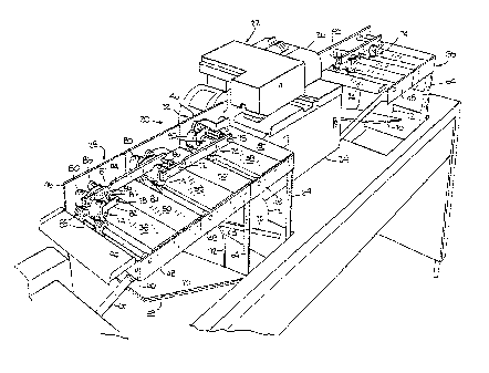
Fig. 1 is a perspective view of a mailing machine in
line with two upstream units consisting of three universal
modules and one downstream unit consisting of two modules
in accordance with the instant invention;
Fig. 2 is an enlarged perspective view of the two
upstream units seen in Fig. 1;
Fig. 3 is an enlarged perspective view of the units
seen in Fig. 2 but the view is from the opposite side of
the apparatus shown;
Fig. 4 is a perspective view of two modules connected
together to form one unit and a stand-alone third module:
Fig. 5 is a perspective view showing the bracketry used
to connect the universal modules;
Fig. 6 is an enlarged, perspective view showing the
universal module transport deck and the drive for a
pivotable panel in the deck of the universal module;
Fig. 7 is a sectional view taken on the plane indicated
by the line 7-7 in Fig. 6;
Fig. 8 is a sectional view taken on the plane indicated
by the line 8-8 in Fig. 7;
Fig. 9 is a top plan view of the downstream unit seen
in Fig. 1 consisting of a pair of universal modules hooked
together;
Fig. l0 is a sectional view taken on the plane
indicated by the line 10-10 in Fig. 9;
Fig. ll is an elevational view of the upstream end of
the upstream module forming part of the upstream unit seen
in Fig. 1;
3o Fig. 12 is a top plan view of three universal modules
connected in which the downstream module employs a top,
braking roller which is stopped to turn an envelope and
thus denote the end of a particular grouping of envelopes;
2~~~2~2
-4_
Fig. 13 is a vertical sectional view taken on the plane
indicated by the line 13-13 in Fig. 12 but the upstream
deflectable panel is shown opened to permit an envelope to
be directed to the upstream stacking bin;
Fig. 14 is an enlarged, perspective view of the braking
roller assembly seen in Figs. 12 and 13;
Fig. 15 is an enlarged, top plan view of the braking
roller seen in Fig. 14;
Fig. 16 is a side elevational view of the braking
roller seen in Fig. 15.
Description of the Preferred Embodiment
In describing the preferred embodiment of the instant
invention, reference is made to the drawings wherein there
is seen in Fig. 1 an envelope transporting system generally
designated 20 consisting of a mailing machine 22 having a
base 24 and a postage meter 26 secured thereto. Upstream
of the mailing machine 22 are three modules 28, 30 and 32
which are connected together to form two stacking units (to
be discussed in more detail hereinbelowj and a transport
path. Downstream of the mailing machine 22 are two modules
34 and 36 which are connected together to form one stacking
unit and a transport path.
Each of the modules 28, 30, 32, 34 and 36 includes an
envelope diverting deck panel 38 which is pivotable about
its central axis on a pivot shaft 40 and a pivot stud 42
which engage flange portions 44 of the deck panel 38. The
pivot shaft 40 is welded to the flange 44 of the panel 38,
and is rotatably mounted through an aperture in the rear
frame 46 which also functions as an aligning or
registration wall. The pivot stud is rotatably mounted
through an aperture in the front frame 48. Each of the
modules 28, 30, 32, 34 and 36 includes downstream of the
envelope diverting deck panel 38 a fixed transport panel
~O~J232
-5-
50. The shaft 40 is secured to a flexible coupling 52
which in turn is secured to a shaft 54 which is journalled
in a supporting bracket 55 and engaged for rotation when a
solenoid 56 (see Fig. 6) is actuated. The solenoid 56 is
secured to the frame 46.
The pivotable deck 38 is easily pivoted by minimal
force generated by the solenoid 56 so that the upstream
portion of the panel 31 forms an acute angle with the
horizontal. Preferably, the acute angle is between about
30 and 45 degrees. The flexible coupling 52 functions as a
shock absorber which also aligns the axial shafts 40 and
54. It can be understood that the centroid location of the
pivot of the deck panel 38 assures that the panel 38 will
not lock on an envelope 76 which may be passing into a
stacking chamber 58 (to be discussed in detail hereinbelow)
situated beneath the panel 38.
The supporting structure for the transport path defined
by the panels 38 and 50 can best be seen in Figs. 4 and 5.
The rear panel 46 is connected to the front.panel 48 by a
side panel 60. Each of the modules also includes a bottom
panel 62 extending transversely from the bottom of the rear
panel 46. Depending on how the module is deployed, there
may be a straight leg 64 extending from the front side of
the side panel 60 to the bottom panel 62, or on an angled
leg 66 extending from the side panel 60 to the rear panel
46.
Each module is capable of being fitted with a stacking
chamber 58 consisting of an angled bottom tray 70 and a
front wall 72. As best seen in Figs. 10 and 13, a pair of
3o modules must be connected together to createlenough space
in the direction of transport for the deployment of a
stacking chamber 58.
Associated with each module 28, 30, 32, 34 and 36 is a
roller assembly generally designated 74 for transporting
-6-
and aligning along the rear frame 46 a series of envelopes
6. Each roller assembly 74 includes a supporting shaft 78
fixedly mounted in the rear frame 46 for supporting a pair
of top, idler rollers 80, each of which is rotatably
mounted on a pivotable lever arm 82. A pair of torsion
springs 84 are mounted on the shaft 78 and are attached to
each arm 82 and a pair of disks 86 also fixedly secured to
the shaft 78. A resultant clockwise movement is therefore
applied to each roller 80 and a normal force is applied to
to a pair of lower, driven rollers 88 associated with each of
top rollers 80. The lower, driven rollers 88 are fixedly
mounted on a drive shaft 90 journalled in the frames 46 and
48. The lever arm 82 has an end portion 82a which is bent
at about a 10 degree angle with respect to its major
longitudinal direction which is substantially parallel to
the rear frame 46. The result is that the axis of the
roller 80 is oriented at about 10 degrees with respect to
the shaft 90 and roller 88. Although the lower rollers 88
are the driven rollers, the top rollers 80 could be driven
and the bottom rollers 88 be the idler rollers.
The lower rollers 88 includes an elastomeric cover
which is divided into a plurality of disks 92 (see Fig. llj
separated by lateral grooves uniformly spaced across the
width of the roller 88 to permit lateral deflection
thereof. As best seen in Figs. 2, 10 and 13, the lower
roller also includes radial slots 94 which divide each of
the disks 92 into radial segments equally about their
circumference. The radial segments resemble flower petals
which easily bend laterally when so influenced. As best
seen in Figs. 1-3, a stabilizing yoke 94 may be used in
order to connect adjacent supporting shafts 78 so that the
top rollers 80 are further stabilized.
Referring now to Figs. 12-16, the top roller nearest
the front frame 48 comprises a straight, braking roller 96
~o~~~~~
_7_
which is controlled by an electronic brake 98. Cooperating
with the braking roller 96 is a lower, driven, steel roller
99. When it is desired to mark the end of a particular
grouping of envelopes 76, such as all those bearing the
same zip code, the transporting system 20, by means of
markings on the envelopes 76 and sensing devices responsive
to those markings, causes the electronic brake 98 to effect
a momentary stoppage of the braking roller 96. The lower,
driven steel roller 99 continues to rotate, but because the
top roller is braked, the lower roller 99 just slips
beneath the envelope 76 without engaging it. The result is
that only the inside rollers 80 and 88 engage the envelope
76, which causes the envelope 76 to be rotated as seen in
Fig. 12, thereby distinguishing the rotated envelope 76
from the balance of the envelopes 76 being processed. The
use of the braking roller 96 to mark an envelope is
especially useful in the case of those envelopes 76 which
are defectively filled with inserts. In such a case,
typically the defective envelope 76 would be diverted to
one of the stacking chambers 58, where it would
subsequently be manually removed and checked for the proper
inserts, but then if it were desired to restore the removed
envelope 76 to its original place in the original grouping,
an additional effort would be required by the machine
operator. If the defective envelope 76 is simply marked by
being turned as by the braking roller 96, then no
additional effort is required to restore the marked
envelope 76 to its original position in the grouping.
The operational capacities of the modules 28, 30, 32,
34 and 36 will now be explained. Clearly, when the
pivotable deck panel 38 is in the horizontal position, the
aforesaid modules function as a transport surface for the
envelopes 76. This transport surface can be situated
adjacent or between any other type of module, such as the
_g_
mailing machine 22, or an inserting machine or an envelope
turning device. The rollers 80 and 88 in combination with
the rear frame 46 provide the capability of aligning the
envelopes 76 so that they are properly registered prior to
the printing thereon of postage, as, for example, by the
postage meter 26. Because of the presence of the pivotable
panel 38, it is possible to divert envelopes underneath the
panel 38 when it is tilted to wn acute angle of about 30 to
45 degrees as seen in Figs. 6, 10 and 13. When the panel
38 is so tilted, the envelope 76 passes beneath the panel
38 into one of the stacking chambers 70 for subsequent
manual handling. Thus it can be seen that the module of
the instant invention can be used for transporting,
aligning and stacking of envelopes and can be deployed in a
variety of environments.
It should be understood by those skilled in the art
that various modifications may be made in the present
invention without departing from the spirit and scope
thereof, as described in the specification and defined in
the appended claims.