Sélection de la langue

Search

Sommaire du brevet 2017097 

Énoncé de désistement de responsabilité concernant l'information provenant de tiers

Une partie des informations de ce site Web a été fournie par des sources externes. Le gouvernement du Canada n'assume aucune responsabilité concernant la précision, l'actualité ou la fiabilité des informations fournies par les sources externes. Les utilisateurs qui désirent employer cette information devraient consulter directement la source des informations. Le contenu fourni par les sources externes n'est pas assujetti aux exigences sur les langues officielles, la protection des renseignements personnels et l'accessibilité.

Disponibilité de l'Abrégé et des Revendications

L'apparition de différences dans le texte et l'image des Revendications et de l'Abrégé dépend du moment auquel le document est publié. Les textes des Revendications et de l'Abrégé sont affichés :

  • lorsque la demande peut être examinée par le public;
  • lorsque le brevet est émis (délivrance).
(12) Demande de brevet: (11) CA 2017097
(54) Titre français: RACCORD AJUSTABLE
(54) Titre anglais: ADJUSTABLE CONNECTION APPARATUS
Statut: Réputée abandonnée et au-delà du délai pour le rétablissement - en attente de la réponse à l’avis de communication rejetée
Données bibliographiques
(51) Classification internationale des brevets (CIB):
  • F16L 27/12 (2006.01)
  • E01D 19/04 (2006.01)
  • E21B 43/013 (2006.01)
  • F16B 7/14 (2006.01)
  • F16L 15/02 (2006.01)
(72) Inventeurs :
  • HART, BRIAN (Royaume-Uni)
(73) Titulaires :
  • COOPER CAMERON CORPORATION
(71) Demandeurs :
  • COOPER CAMERON CORPORATION (Etats-Unis d'Amérique)
(74) Agent: DEETH WILLIAMS WALL LLP
(74) Co-agent:
(45) Délivré:
(22) Date de dépôt: 1990-05-18
(41) Mise à la disponibilité du public: 1991-03-14
Requête d'examen: 1992-12-08
Licence disponible: S.O.
Cédé au domaine public: S.O.
(25) Langue des documents déposés: Anglais

Traité de coopération en matière de brevets (PCT): Non

(30) Données de priorité de la demande:
Numéro de la demande Pays / territoire Date
07/443,388 (Etats-Unis d'Amérique) 1989-11-30
89309339.3 (Office Européen des Brevets (OEB)) 1989-09-14

Abrégés

Abrégé anglais


ABSTRACT OF THE DISCLOSURE
An adjustable connection apparatus for joining tubular
members including a first tubular member with a central bore, a
counterbore on one end thereof, a flange on the other end
thereof and external fine pitch grooves and ridges, a second
tubular member with a central bore, a flange on one end thereof,
a first reduced external diameter portion on the opposite end
for insertion into said counterbore of said first tubular
member, a second reduced diameter portion on the end of said
first reduced diameter portion with external threads on the end
of said second reduced diameter portion and external fin pitch
grooves and ridges, clamping elements having internal fine pitch
grooves and ridges for gripping engagement with the external
grooves and ridges of said tubular members and means for
securing the clamping elements together in gripping engagement
with the tubular members to secure them into a joint having a
preselected length and sealing means between the tubular
members.

Revendications

Note : Les revendications sont présentées dans la langue officielle dans laquelle elles ont été soumises.


- 6 -
The embodiments of the invention in which an exclusive
property or privilege is claimed are defined as follows:
1. An adjustable length connection apparatus comprising a
first tubular member having a central bore, a counterbore at one
end thereof, means for connecting the first tubular member into
a flowline at the opposite end from said one end and external
grooves and ridges, a second tubular member having a central
bore, a reduced outer diameter at one end thereof, means for
connecting the second tubular member into a flowline at the
opposite end from said one end and external grooves and ridges,
a pair of mating clamping sections having internal grooves and
ridges for mating with the external grooves and ridges on said
first and second tubular members and means for joining the
clamping sections into tight engagement with the exterior of
said first and second tubular members, and sealing means
positioned between the first and second tubular members within
the counterbore of the first tubular member and around the
reduced diameter portion of the second tubular member.
2. An adjustable length connection apparatus according to
claim 1 wherein the grooves and ridges of said connection
apparatus have a relatively fine pitch.
3. An adjustable length connection apparatus according to
claim 1 including a second reduced diameter portion on the end
of the first reduced diameter portion of said second tubular
member, said sealing means being positioned on said second
reduced diameter portion of said second tubular member.
4. An adjustable length connection apparatus according to
claim 3 including a nut threaded on the end of said second
tubular member to retain said sealing means thereon.
5. An adjustable length connection apparatus according to
claim 1 wherein said sealing means includes a resilient sealing
ring, and a metal cup sealing ring.

Description

Note : Les descriptions sont présentées dans la langue officielle dans laquelle elles ont été soumises.

4-217(D) CVE-384
ADJUS'rABLE CONNECTION APPARA~US
DESCRIPTION
BACKGROUND
The present invention relates to an adjustable connection
apparatus which has particular application to the connection of
retrievable jumper flowlines between a subsea template and a
~lowline pull-in apparatus which allows the vertical and
horizontal runs to be preset and lowered to the subsea location
to be hydraulically set by a remotely operated vehicle (ROV).
U. S. Patent No. 1,213,132 discloses a pipe coupling which
includes two half sections and bolts tightening the half
sections on the ends of pipes to be joined which pipes are non-
rotatable. The pipe end~ and the portions of the coupling which
engage each pipe end have different threads or engaging surfaces
to allow rotation of the coupling after it is securely attached
to the pipP ends so that the pipe ends are pulled toward each
other. A suitable metal ring or other type packing is suggested
between the end surfaces of the pipe ends within the coupling to
ensure a sealed relationship of the end surfaces.
U. S. Patent No. 4,008,972 di~closes a tubing connector
which is intended to be used to join a tool to a tubing string
and includes a split clamp around the exterior of the tubing
~tring and a mandrel within the tubing string and tightening
means to provide a tight engagement between the three compo-
nents. It is suggested that taeth may be on the interior of the
clamp or on the exterior of the mandrel (prefe~ably on the
interior of the clamp) or both to provide the secure engagement
between the clamp and the string.
U. S. Patent No. 4,175,405 discloses a coupling used
between shafts which are transmitting rotary power so that a
section of shafting may be removed without having to remove all
the sha~ting to repair only one section. Each sha~t i.s provided

- !~ Q ~ 7 0 ~ 7
with split collar~ having a groove to receive the shaft key and
axially extending openings to receive drive pins which engage
the collars or the opposing shaft end to transmit the rotary
power. A pair of hou~ing sections clamp the ends together with
seals and bearings into an aligned configuration for the
transmission of rotary power between the sha~ts.
U. S. Patent No. 4,603,887 discloses an ad~ustable length
tubing connection with a first or outer member having a smooth
interior and an outwardly extending end flange and a second or
inner member having external threads and being slidably movable
within the first member and a clamp to engage the first member
flange and the second member threads to clamp them together.
The clamp is rotatable to adjust the length of the two members.
SUMMARY
An improved adjustable length connection apparatus includ-
ing a first tubular me~ber having external fine pitch grooves
and a second tubular member having external fine pitch grooves,
one of said tubular member~ having an external end recess and
ZO the other having an internal end recess allowing said members to
be interengaged, a split clamp having internal ~ine pitch
grooves to match with said external fine pitch grooves of said
tubular members and means for tightening said split clamp on
said tubular members to retain them in their preselecte~
positions relative to each other~ Suitable seal means is
provided between the exterior of the tubular member positioned
within the other tubular member including a primary metal-to-
metal seal and a secondary resilient seal.
An object of the present invention is to provide an
improved adjustable joint suitable for use in jumper ~lowlines
in a subsea location.
Another object is to provide an improved adjustable
connection apparatus ~or joining tubular members which is
adjustable in length and provides a suitable seal between the
members on the interior o~ one member~

~ 13 ~ 7
-- 3 --
A further object is to provide an improved adjustable
connection apparatus which when set functions to retain the
connected memhers together without other locking elements.
BRIEF DESCRIPTION OF THE DRAWINGS
These and other objects and advar~tages of the present
invention are hereinafter disclosed and explained with reference
to the drawings wherein:
FIGURE 1 is a plan view o~ a pair of subseal templates
which are connected to a flow line pull-in apparatus by jumper
flow lines including the improved adjustable connection appara-
tus of the present invention.
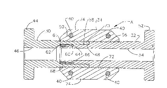
FIGURE 2 is a seckional view of the improved adjustable
connection apparatus o~ the present invention in a first short
length position.
FIGURE 3 is a sectional view similar to FIGURE 2 showing
the improved adjustable apparatus in an extended position in
comparison to the apparatus shown in FIGURE 2.
DESCRIPTION OF THE PREFERRED EMBODIMENT
Template 10 shown in FIGURE l is spaced from template 12
and its flowline 14 connects into line 16 from templata 10 to
jumper flowline 18 which is connected to the flowline pull-in
apparatus 200 Similarly, flowline 22 from template 12 is
connected to line 24 to jumper flowline 26 which is connected to
flowline pull-in apparatus 28. Jumper flowlines 18 and 26
include improved adjustable connection apparatus A of the
present invention and are also provided with suitable hydraulic
means (not shown) which can be operated by an ROV to provide the
connections to the template flowlines 14 and 24 and to the pull-
in apparatus 20 and 28.
As shown in Figures 2 and 3, adjustable connection appara-
tus A includes first tubular member 30, second tubular member
32, split clamp 34 including clamp sections 36 and 38 and
~astening means, such as bolts 40 and nuts 42 for securing

g ~
section 36 and 38 together and for tightening them on the
exterior of members 30 and 32 as hereinafter explained.
First tubular member 30 includes end flange 44 secured on
one end thereof with central bore 46 extending through member 30
and ending in counterbore 48 which extends to the end o~ member
30. The exterior of member 30 includes a plurality of fine
pitch grooves and ridges 50 which may be threads or annular
grooves and ridges.
Second tubular member 32 includes end flange 52 secured on
one end thereof with central bore 54 extending completely
therethrough. The exterior of second tubular member 32 includes
a plurality of fine pitch grooves and ridges 56 which may be
threads or annular grooves and ridges. Grooves and ridges 56
end in first reduced diameter portion 58 which extends toward
the end of member 32 and ends in second reduced diameter portion
60 which in turn ends in external threads 62. First internal
reduced diameter portion 58 has a diameter whiah fits within
counterbore 48. Resilient seal 64 is positioned in surrounding
relationship to the in~er portion of second reduced diameter
portion 60 for sealing against the interior of counterbore 48.
Netal cup sealing 66 is positioned around second reduced
diameter portion 60 between resilient seal 64 and nut 68 is
threaded onto external threads 62. Nut 68 is provided to secure
seals 64 and 66 on second reduced diameter portion 60 and has an
external chamber to allow easy entry with counterbore 48 of
first tubular member 30. First reduced diameter portion 58
de~ines shoulder 70 which forms a stop limiting the entry of the
outer end of second tubular member 32 into counterbore 58 of
first tubular member 30.
Clamp sections 36 and 38 include internal grooves and
ridges 72 which are mated for engagement with grooves and ridges
50 and 56 on the exterior of tubular members 30 and 32 and also
include axially extending flangas 74 with bolts 40 extending
through openings 76 therein. Thus, when bolts 40 and nuts 42
are tightened, clamp sections 36 and 38 are brought in tight

7 ~ ~ ~
engagement with the exterior grooved surfaces of members 30 and
32 to secure and retain them in their desired po~ition.
As shown in FI~UR~ 2 members 30 and 32 are telescoped
within one another as far as possible so that the end of member
30 engages the stop shoulder 70 on member 32. When it is
desired to have the joint of members 30 and 32 be longer it is
only necessary to position mem~er 32 in a position which is not
totally within counterbore 48 of membar 30 as shown in FIGURE 3.
With members 30 and 32 in their desired positions so that the
joint is as long as desired, clamp sections 36 and 38 are
tightened thereon and the joint established thereby will have
the desired length without sacrificing the integrity of the
flowline or having problems with further relative movement of
the membersO
In some applications, it may be desirable to have connec-
tion apparatus A infinitely adjustable rather incremently. In
those situations, it may be desirable to make the grooves and
ridge fine lead threads.

Dessin représentatif
Une figure unique qui représente un dessin illustrant l'invention.
États administratifs

2024-08-01 : Dans le cadre de la transition vers les Brevets de nouvelle génération (BNG), la base de données sur les brevets canadiens (BDBC) contient désormais un Historique d'événement plus détaillé, qui reproduit le Journal des événements de notre nouvelle solution interne.

Veuillez noter que les événements débutant par « Inactive : » se réfèrent à des événements qui ne sont plus utilisés dans notre nouvelle solution interne.

Pour une meilleure compréhension de l'état de la demande ou brevet qui figure sur cette page, la rubrique Mise en garde , et les descriptions de Brevet , Historique d'événement , Taxes périodiques et Historique des paiements devraient être consultées.

Historique d'événement

Description Date
Inactive : CIB de MCD 2006-03-11
Demande non rétablie avant l'échéance 1997-05-20
Le délai pour l'annulation est expiré 1997-05-20
Réputée abandonnée - omission de répondre à un avis sur les taxes pour le maintien en état 1996-05-20
Exigences pour une requête d'examen - jugée conforme 1992-12-08
Toutes les exigences pour l'examen - jugée conforme 1992-12-08
Demande publiée (accessible au public) 1991-03-14

Historique d'abandonnement

Date d'abandonnement Raison Date de rétablissement
1996-05-20
Titulaires au dossier

Les titulaires actuels et antérieures au dossier sont affichés en ordre alphabétique.

Titulaires actuels au dossier
COOPER CAMERON CORPORATION
Titulaires antérieures au dossier
BRIAN HART
Les propriétaires antérieurs qui ne figurent pas dans la liste des « Propriétaires au dossier » apparaîtront dans d'autres documents au dossier.
Documents

Pour visionner les fichiers sélectionnés, entrer le code reCAPTCHA :


Pour visualiser une image, cliquer sur un lien dans la colonne description du document. Pour télécharger l'image (les images), cliquer l'une ou plusieurs cases à cocher dans la première colonne et ensuite cliquer sur le bouton "Télécharger sélection en format PDF (archive Zip)" ou le bouton "Télécharger sélection (en un fichier PDF fusionné)".

Liste des documents de brevet publiés et non publiés sur la BDBC .

Si vous avez des difficultés à accéder au contenu, veuillez communiquer avec le Centre de services à la clientèle au 1-866-997-1936, ou envoyer un courriel au Centre de service à la clientèle de l'OPIC.


Description du
Document 
Date
(aaaa-mm-jj) 
Nombre de pages   Taille de l'image (Ko) 
Page couverture 1991-03-14 1 14
Dessins 1991-03-14 3 65
Revendications 1991-03-14 1 49
Abrégé 1991-03-14 1 27
Description 1991-03-14 5 223
Dessin représentatif 1999-07-16 1 23
Taxes 1994-04-05 1 42
Taxes 1995-03-23 1 39
Taxes 1993-03-24 1 25
Taxes 1992-03-24 2 86