Note : Les descriptions sont présentées dans la langue officielle dans laquelle elles ont été soumises.
2017989
1 55,160
A ~Y8TE~ AND METHOD FOR ~EAT RECOVE~Y
IN A CONBINED CYCLE ~O~E~ PLAN~
BACRGROUND OF T~E INVENTION
Field of the Invention
This invention relates generally to a method
for generating steam by recovering heat from the exhaust
gas of a gas turbine operating in a combined cycle power
plant. The steam is expanded in one or more steam
turbines which, together with the gas turbine, produce
electrical power.
De~cription of the Prior Art
The low capital cost, short lead times and
flexibility of gas turbine-based power plants make them
particularly attractive to electrical utilities as a
means for generating electrical power. Unfortunately,
the inefficiency of a gas turbine standing alone,
referred to as a simple cycle system, is relatively low
compared to conventional fired boil steam turbine
systems. The major source of this inefficiency is
inherent in the Brayton cycle on which the gas turbine
operates. The Brayton cycle operates in three phases -
first, work is performed on the fluid (air in the case
of a gas turbine) by isentropic compression in a
compressor; second, heat is added to the fluid
isobarically in a combustor; and, third, the hot
compressed fluid is isentropically expanded back down to
its initial pressure in the turbine. During the
expansion phase much of the energy imparted to the fluid
2017989
2 55,160
as a result of the compression and heating is recovered
in the form of useful work. However, a significant
portion of the energy remains in a relatively high-
temperature, low-pressure form which, as a practical
matter, cannot be recovered by further expansion in the
turbine. In a simple cycle system this energy is lost
to the atmosphere when the gas exhausting from the gas
turbine is vented to atmosphere. The magnitude of this
energy loss can be appreciated by noting that in a
typical simple cycle system, air inducted into the
compressor at ambient temperature is heated to
approximately 2000F in the combustor prior to expansion
in the turbine but is only cooled to approximately
1000F when vented to atmosphere after expansion in the
turbine. Thus, the portion of the fuel burned in the
combustor which was used to raise the temperature of the
ambient air to 1000F is wasted, resulting in poor
overall thermodynamic efficiency.
Consequently, substantial effort has been
expended in developing methods for recovering the energy
available in the gas exhausting from a gas turbine. One
of the most successful methods involves the transfer of
latent heat from the hot exhaust gas to pressurized
feedwater in a heat recovery steam generator
(hereinafter HRSG). The HRSG generates steam which is
expanded in a steam turbine producing additional
rotating shaft power. Since steam turbines operate on
the Rankine cycle, rather than the Brayton cycle, power
plants employing such a heat recovery method are termed
combined cycle power plants.
Typically, a HRSG is comprised of a large duct
through which the exhaust gas flows. The duct encloses
banks of tubes through which the water/steam flows and
over which the gas turbine exhaust gas flows. The
surfaces of the tubes provide heat transfer surfaces.
There are three basic components in which heat is
transferred in a typical HRSG, each comprised of a
20179~39
55,160
bundle of tubes: an economizer in which the feedwater is
heated to near-saturation temperature; an evaporator in
which the water heated in the economizer is converted to
steam; and a superheater in which the temperature of the
saturated steam from the evaporator is raised into the
superheat region.
In order to obtain maximum efficiency of the
steam turbine, it is desirable to generate steam at a
high temperature and pressure. However, unless
supplemental fuel is burned in the exhaust gas, an
inefficient practice, the steam temperature is limited
to the temperature of the exhaust gas entering the HRSG.
The maximum pressure of the steam is also limited by the
temperature of the exhaust gas since the saturation
temperature of steam increases with its pressure and
only the portion of the heat in the exhaust gas which is
above the saturation temperature of the water in the
evaporator can be used to generate steam. Hence,
although increasing steam pressure increases steam
turbine efficiency, it also reduces the quantity of the
steam generated. Thus maximum heat recovery, and
therefore maximum plant power output, are obtained by
optimizing the relationship between the steam pressure
and steam flow.
one optimization method utilizes a HRSG which
generates steam at multiple pressure levels by employing
a separate evaporator at each pressure level. The gas
turbine exhaust gas is directed to the highest pressure
evaporator first, then each successive lowar pressure
level evaporator. Thus, although the temperature of the
gas entering the evaporator decreases at each successive
pressure level, the saturation pressure and hence
saturation temperature of the water in each successive
evaporator is also reduced, so that additional steam may
be produced at each pressure level.
Thus, it is desirable to devise a method of
heat recovery which employs the optimum number of
~(~17989
4 55,160
pressure levels, each operating at its optimum pressure,
and which utilizes the steam produced at each pressure
level in the optimum manner.
In many earlier combined cycle power plants,
feedwater returned from the condenser at low temperature
was not entered directly into the HRSG for heating prior
to deaeration. Instead, feedwater heating was
accomplished indirectly, using steam generated in a low-
pressure evaporator or extracted from an intermediate
stage of a low-pressure steam turbine. Although such
methods ensured that the exhaust gas would not be cooled
below its acid dew point temperature, they limited the
amount of heat which could be recovered from the exhaust
gas and reduced the steam available to generate
electrical power.
Thus, it would be desirable to devise a method
of heating the feedwater using heat removed from the
exhaust gas directly, and to do so without encountering
the dangers of acid corrosion due to excessive cooling
of the exhaust gas in the HRSG.
8UMM.~RY OF TNE INVENTION
Accordingly, it is the general object of the
present invention to provide a means for recovering heat
from the exhaust gas of gas turbine and utilizing such
recovered heat to generate steam.
More specifically, it is an object of the
present invention to provide a means for recovering as
much heat as possible from the exhaust gas of a gas
turbine without reducing the temperature of the exhaust
gas below its acid dew point temperature. Moreover,
such means must allow for variations in the acid dew
point temperature resulting from variations in the
sulfur content of the fuel burned in the gas turbine.
It is another object of the invention to
utilize the steam generated as efficiently as possible,
maximizing the steam expanded in the steam turbine and
minimizing the steam used for feedwater heating.
Z~)17989
55,160
It is still another object of the invention to
generate sufficient steam for injection into the
combustor of a gas turbine to reduce the concentration
of nitrogen oxides in the exhaust gas to acceptable
levels.
Briefly, these and other objects of the
present invention are accomplished in a HRSG having a
deaerator, feedwater heater and three boiler sections,
each boiler section operating at a different pressure
level. In accordance with the invention, when low
sulfur fuel is burned, all of the heat necessary for
deaeration is provided by the feedwater heater so that
all of the steam generated in the low-pressure boiler
section can be expanded in a low-pressure steam turbine,
producing useful power. When high sulfur fuels are
burned, the amount of heat recovered in the feedwater
heater is reduced by decreasing the flow rate of
feedwater to the heater, thereby avoiding excessive
cooling of the exhaust gas and the attendant acid
condensation. Steam bled from the low-pressure boiler
section compensates for any short fall in the heat
necessary for deaeration.
In accordance with the invention, all of the
steam produced in the medium-pressure boiler section is
in~ected into the gas turbine combustor, reducing the
concentration of nitrogen oxides in the exhaust gas and
producing additional power. All of the steam produced
in the high-pressure boiler section is expanded in a
high-pressure steam turbine providing a source of
rotat~ng shaft power. In addition, steam produced in
the low-pressure boiler section is expanded in a low-
pressure steam turbine, contributing to the power
production.
BRIEF DE8C~IPTION OF q~HE DRA~ING8
Figure 1 is a schematic diagram of a combined
cycle power plant.
2~)17989
6 55,160
Figure 2 is a schematic diagram of the HRSG
portion of the combined cycle power plant shown in
Figure 1.
Figure 3 is a schematic diagram of the
feedwater splitter valve and low-pressure steam bleed
valve control system.
Figure 4 is a heat transfer diagram for the
HRSG.
DE~CRIPTION OF THE PREFERRED EMBODIMENT
Figure 1 shows a schematic diagram of a
combined cycle power plant. Ambient air 2 is inducted
into the compressor 5 of a gas turbine 1. The
compressed air is then heated in a combustor 4 by
burning fuel 3. The fuel may be in a liquid or gaseous
form, and is typically No. 2 distillate oil or natural
gas. The heated compressed gas is then expanded in the
turbine section 6 of the gas turbine, producing power to
drive the compressor 5 as well as a dynamo electric
machine 8, thereby generating electrical power. The
spent exhaust gas 7 is then ducted to a HRSG 9. After
leaving the HRSG the exhaust gas lO is vented to
atmosphere.
The HRSG receives feedwater 16 and, by
transferring heat to the feedwater from the exhaust gas
7, converts the feedwater into steam at three different
pressure levels. Medium-pressure steam 20 is injected
into the combustor 4 of the gas turbine. As is well
known in the art, such steam injection reduces the
concentration of nitrogen oxides in the exhaust gas,
thereby enabling the combined cycle power plant to
satisfy local air pollution requirements. In addition,
the steam increases the mass flow of the gas expanded in
the turbine section 6 of the gas turbine, thereby
increasing the power output of the turbine.
High-pressure steam 19 i~ supplied to a high-
pressure steam turbine 11. The steam 18 exhausted from
the high-pressure steam turbine is combined with low-
2017989
7 55,160
pressure steam 17, generated by the HRSG, and inducted
into a double-flow low-pressure steam turbine 12. The
high-pressure and low-pressure steam turbines drive a
common shaft which turns a second dynamo electric
machine 13, producing additional electrical power. The
steam 60 exhausting from the low-pressure steam turbine
is liquified in a condenser 14 by transferring heat from
the steam to circulating water 59. The circulating
water is typically obtained from a nearby lake or river
or may be recirculated and cooled through atmospheric
cooling towers (not shown). The liquified steam is
mixed in the condenser hotwell with make-up water 15.
The quantity of the make-up water is sufficient to
compensate for losses due to blowdown from the steam
drums and leakage throughout the system as well as the
medium-pressure steam injected into the gas turbine
combustor. The condensed steam and make-up water are
drawn from the condenser by pump 61 and form the
feedwater 16 which enters the HRSG, providing, except
for the steam injection and make-up water, an
essentially closed-loop system.
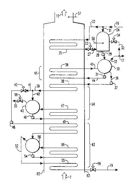
Figure 2 shows a schematic diagram of the HRSG
9 shown in Figure 1~ The HRSG duct 62 receives exhaust
gas 7 from the gas turbine and discharges the gas 10,
after recovering useful heat therefrom, to the
atmosphere. The HRSG is comprised of three boiler
sections 63, 64, and 65, a feedwater heater 25 and a
deaerator 24. The gas exhausting from the gas turbine
flows over the high-pressure boiler section 63 first,
then the medium-pressure boiler section 64, then the
low-pressure boiler section 65 and lastly the feedwater
heater 25.
Since the quantity of make-up water needed is
small compared to the flow rate of condensed steam, the
temperature of the feedwater is very close to that of
the condensate. The temperature of the condensate is
the saturation temperature of the steam when it
2nl7sss
8 55,160
liquifies and hence is a function of the pressure in the
condenser. Since maximum steam turbine power is
produced by expanding the steam to as low a pressure as
possible, such condensers usually operate at
subatmospheric pressure. Hence, feedwater temperatures
are usually in the 26-38C (80-lOO'F) range (range in
steam saturation temperature corresponding to pressures
in the 3-lO kPa absolute (1-3 inches HGA) range).
As a result of leakages of air into the
system, oxygen and other non-condensable gases are
dissolved in the feedwater. These must be removed
before returning the feedwater to the HRSG in order to
avoid corrosion of the equipment. In combined cycle
power plants gas removal is accomplished in a vessel,
termed a deaerator, which vents the removed gases to
atmosphere. In accordance with the present invention,
the feedwater 16 supplied to the HRSG is split into two
streams 21 and 22, shown in Figure 2. Stream 21 enters
the deaerator 24, which may be of the spray tray type,
directly, while stream 22 enters a feedwater heater 25.
Feedwater splitter valve 23, disposed in a pipe
transporting the feedwater discharged from the feedwater
heater 25, regulates the relative quantity of flow in
each stream.
Feedwater heater 25 is immersed in the exhaust
gas near the discharge end of the HRSG, as shown in
Figure 2, and is comprised of one-or more rows of tubes
through which feedwater stream 22 flows and over which
the exhaust gas from the gas turbine flows. The tubes
provide heat transfer surfaces which facilitate the
heating of the feedwater. As a result of the action of
pump 61, shown in Figure l, the pressure of the water in
the feedwater heater is high enough to insure that the
temperature of the water in the feedwater heater remains
below its saturation temperature. Hence, the feedwater
heater produces hot water, but no steam is generated
therein.
2()17989
9 55,160
In order to reduce gas solubility, the water
to be deaerated must be heated to its saturation
temperature. Feedwater heater 25 forms a heat source
for the deaerator by discharging the heated water 27
into the deaerator 24 where it mixes with the unheated
feedwater which formed stream 21. In order to
facilitate the driving off of the gases, deaerators must
be operated above atmospheric pressure. However, the
higher the pressure in the deaerator the higher the
saturation temperature and hence the greater the heat
input required. Thus, in the preferred embodiment the
deaerator pressure is maintained in the 140-210 kPa
absolute (20-30 psia) range so that the saturation
temperature which must be achieved is in the 110-120C
(230-250F) range. Presss~re in the deaerator is
maintained by regulating the heat input to the deaerator
- too much heat input will cause a large portion of the
water in the deaerator to convert to steam resulting in
excessive pressure. Too little heat input will drop the
temperature of the water below saturation temperature
and result in insufficient pressure for good deaeration.
According to the current invention, the
desired pressure is maintained in the deaerator by
operating the feedwater splitter valve 23 to regulate
the relative quantities of heated 27 and unheated 21
feedwater entering the deaerator. It is important to
note that the feedwater heater has sufficient heat
transfer area to enable it to supply all of the heat
required to heat the feedwater in the deaerator when the
combined cycle power plant is operating at the maximum
feedwater flow rate.
The deaerated water 28 is then drawn off the
deaerator and, after its pressure is increased by pump
29, it enters the steam drum 30 of the low-pressure
boiler section 65. The low-pressure boiler section is
comprised of a steam drum 30, a circulating pump 31 and
an evaporator 26. The steam drum 30 acts as a storage
2()17989
55,160
reservoir for the circulating pump 31 and also serves to
separate the steam from the steam/water mixture
discharged by the evaporator 26. The circulating pump
31 draws water from the steam drum 30 and forces it
through the evaporator 26. The evaporator 26 consists
of one or more rows of tubes immersed in the exhaust gas
flow. The exhaust gas flows over the tubes and the tube
surfaces act as heat transfer surfaces for heating the
water. There is sufficient heat transfer area in the
tubes to convert a portion of the water 44 circulating
in the evaporator to steam. The water/steam mixture 45
discharged by the evaporator re-enters the steam drum
where the steam is separated from the water. The steam
32 leaves the drum. A portion 44 of the water re-enters
the evaporator and the balance 36 is drawn from the drum
by pump 37 for entry into the medium-pressure boiler
section 64. Since by the time the exhaust gas reaches
the low-pressure evaporator it has already given up much
of its heat in boiler sections 63 and 64, the pressure
in the low-pressure evaporator, and the hence the
saturation temperature, should be maintained at a
relatively low value in order to obtain adequate steam
generation. In the preferred embodiment the pressure in
the low-pressure evaporator is maintained in the 207-480
kPa absolute (30-70 psia) range.
Except when high sulfur fuels are burned as
discussed below, all of the steam 32 produced in the
low-pressure boiler section is transported from the
steam drum 30 to the low-pressure steam turbine 12 for
induction therein, thereby producing additional
electrical power in dynamo-electric machine 13. Thus
the scheme disclosed, wherein all the feedwater heating
necessary for deaeration is accomplished by the direct
transfer of heat from the exhaust gas to the feedwater
heater, provides a significant advantage over many
earlier combined cycle power plants in which a
considerable portion of the low-pressure steam generated
20~7989
11 55,160
in a low-pressure evaporator was used to heat the
feedwater prior to deaeration. Such use of low-pressure
steam for feedwater heating not only robs power from the
low-pressure steam turbine, it reduces the amount of
heat which can be removed from the exhaust gas. This is
so because the temperature of the water in a low-
pressure evaporator is essentially at its saturation
temperature - 120C (250F) in the case of a low-
pressure evaporator operating at 345 kPa absolute (50
psia). Hence none of the heat in the exhaust gas below
120C (250F) can be recovered by transferring it to the
water circulating in the low-pressure evaporator tubes.
However, it must be noted that this limitation in
exhaust heat recovery was deemed necessary in many
earlier combined cycle power plants in order to avoid
acid corrosion of the HRSG, as explained below. In
contrast, the method disclosed herein uses feedwater
from the condenser as a heat sink. Since, as previously
explained, this feedwater is in the 26-38C 580-100F)
range, a significantly greater amount of heat may be
recovered from the exhaust gas.
The exhaust gas from the gas turbine is
comprised of air and the products of combustion of the
fuel burned, including water vapor and sulfur trioxide.
A portion of the water and sulfur trioxide combine to
form sulfuric acid. If the temperature of the exhaust
gas drops below a certain temperature, referred to as
the acid dew point, the sulfuric acid will condense in
the HRSG, causing harmful corrosion. The acid dew point
is a function of the concentration of sulfur trioxide in
the exhaust gas which, in turn, is a function of the
concentration of sulfur in the fuel burned. The higher
the sulfur concentration, the higher the acid dew point,
and hence thP higher the minimum exhaust gas temperature
which may be safely obtained. Consequently, care must
be taken to ensure that the quantity of heat transferred
from the exhaust gas is not great enough to reduce its
Z017989
12 55,160
temperature below the acid dew point. This situation is
complicated by the fact that many gas turbines burn a
variety of fuels and can automatically switch from
natural gas to oil fuel without shutting down. Even if
the type of fuel burned remains constant, sulfur content
may vary over time, in the case of pipeline gas, or
among batches received, in the case of liquid fuel.
Hence the acid dew point may vary from under 93C
(200-F) for clean natural gas to over 150C (300F) for
high sulfur No. 2 distillate oil. A maximum acid dew
point for operation on any given fuel can be calculated
by measuring the sulfur concentration in the fuel and
combining this with the maximum expected fuel
consumption rate and the minimum compressor air flow
rate to determine the maximum concentration of sulfur
trioxide in the exhaust gas. The acid dew point can be
calculated from the sulfur trioxide concentration using
well known methods, for example, see "Estimating Acid
Dew Points in Stack Gases", Chemical Engineering, April
11, 1977 by R. Pierce.
The feedwater heating system disclosed herein
is capable of obtaining very low exhaust gas
temperatures at the discharge 10 from the HRSG. In the
preferred embodiment a gas discharge temperature of 93C
(200F) is achieved. Accordingly, a control scheme has
been devised to prevent excessive cooling of the exhaust
gas when high sulfur fuels are burned. The scheme
features a deaerator pressure control loop and a HRSG
gas temperature control loop. Figure 3 shows a
schematic diagram of the control scheme. The deaerator
pressure control loop operates as follows. Pressure
sensor 58, which may be a transducer, senses pressure in
the deaerator and generates a signal 93 whose amplitude
corresponds to the pressure sensed. Device 82 receives
the signal and compares it to a predetermined value
corresponding to the desired deaerator pressure (in the
preferred embodiment approximately 145 kPa absolute (21
2017989
13 55,160
psia)). If the amplitude of the signal differs from the
predetermined value, device 82 generates a signal 94
which corresponds to whether the flow rate to the
feedwater heater 25 should be reduced, because the
deaerator pressure is too high, or the flow rate to the
feedwater heater should be increased, because the
deaerator pressure is too low. Device 97 receives the
signal 94 and, unless signal 92 has also been received
by device 97 for reasons discussed below, device 97
generates a signal 96 which operates on the feedwater
splitter valve 23 to increase or decrease the flow rate
through the feedwater heater and therefore, the heat
input to the deaerator. As previously explained, the
pressure in the deaerator is maintained by regulating
the heat input to the deaerator.
The HRSG gas temperature control loop operates
as follows. Device 80 allows the input of a temperature
set point corresponding to the minimum temperature
allowable to avoid acid condensation. In the preferred
embodiment this is 10F higher than the maximum acid dew
point, calculated as previously explained based on the
sulfur concentration in the fuel being burned. Device
80 generates a set point signal 91 whose amplitude
corresponds to the temperature set point entered.
Temperature sensor 57, which may be a thermocouple, is
disposed in the HRSG discharge gas flow and generates a
signal 90 whose amplitude corresponds to the temperature
sensed. Device 81 receives and compares the set point
and the temperature sensed signals and determines their
difference. If this difference indicates the gas
temperature has dropped below the set point temperature,
device 81 generates a signal 92 which is received by
device 97 causing it to ignore signal 94, from the
deaerator pressure control loop, and generates a signal
96 to operate the feedwater splitter valve 23 to reduce
the flow rate through the feedwater heater 25 until the
gas temperature reaches the set point value. Thus,
2017989
14 55,160
cooling of the exhaust gas below its acid dew point is
avoided.
Reliance on the control scheme discussed above
may result in inadequate heat input to the deaerator 24
because of low flow through the feedwater heater when
high sulfur fuel is burned. To compensate for this loss
of deaerator heat input, a scheme has been devised
whereby the low-pressure evaporator 26 acts as a
secondary heat source for the deaerator 24. Referring
again to Fiqure 3, it can be seen that signal 93 from
the deaerator pressure sensor 58 is also received by
device 84. Device 84 compares the amplitude of signal
93 to a predetermined value corresponding to the minimum
acceptable deaerator pressure for good deaeration, in
the preferred embodiment this value is 124 kPa absolute
(18 psia). If the amplitude of the signal is less than
the predetermined value, indicating that as a result of
regulation of feedwater splitter valve 23 insufficient
water is being received by the deaerator 24 from the
feedwater heater 25 to maintain deaerator pressure,
device 84 generates a signal 95 which operates a bleed
valve 34. As shown in Figure 2, bleed valve 34 is
disposed in a pipe 33 which draws steam from the low-
pressure steam 32 generated by the low-pressure
evaporator. Opening bleed valve 34 allows a portion of
this steam to be supplied to the deaerator for feedwater
heating. Thus, adequate deaeration may be achieved with
minimum use of steam for feedwater heating, thereby
maximizing steam turbine power generation, and acid
corrosion is avoided regardless of the sulfur content of
the fuel.
Referring again to Figure 2, it can be seen
that the feedwater stream 36, which represents the
portion of the feedwater 28 transferred to the low-
pressure boiler section 65 which is not converted tosteam 32, is transferred to medium-pressure boiler
section 64 after its pressure is raised in pump 37. The
2t)17989
15 55,160
medium-pressure boiler section is comprised of an
economizer 38, a steam drum 43, a circulating pump 46,
and an evaporator 47. The economizer 38 and evaporator
47 are arranged so that the exhaust gas flows over the
evaporator first and then the economi~er. Water from
pump 37 flows through economizer 38, which consists of
one or more rows of tubes, and absorbs heat from the
exhaust gas. The tubes in the economizer provide
sufficient heat transfer surface area to heat the water
to close to its saturation temperature. In order to
maintain maximum heat recovery, it is desirable to
transfer as much heat as possible in the economizer.
However, the temperature of the water must remain below
its saturation temperature to avoid steam formation,
which impedes the flow of water through the economizer.
In the preferred embodiment the water in the economizer
is heated to 3 C (5F) below its saturation temperature.
Water 39 discharged from the economizer 38 is split into
flow streams 41 and 40 by flow control valve 42. Flow
stream 40 enters the steam drum 43 and is circulated by
pump 46 through the evaporator 47. Medium-pressure
evaporator 47 is similar to low-pressure evaporator 26
and has sufficient heat transfer surface area to
generate all the steam required for control of nitrogen
oxides in the gas turbine exhaust. The steam 20
generated is transferred from the drum 43 of the medium-
pressure boiler section to the combustor 4 of the gas
turbine. The steam 20 must have sufficient pressure to
allow it to be sprayed into the compressed gas in the
combustor. Since most modern gas turbines operate with
compressor discharge pressures in the 1035-1725 kPa
absolute (150-250 psia) range, in the preferred
embodiment the pressure in the medium-pressure boiler
section is maintained in the 2070-2410 kPa absolute
(300-350 psia) range by a pressure-regulating valve 98.
Z017989
16 55,160
Flow stream 41 from the discharge of the
medium-pressure economizer 38 is transferred to the
high-pressure boiler section 63 after its pressure has
been raised by pump 48. The high-pressure boiler
section 63 is comprised of an economizer 49, a steam
drum 50, evaporator 66, a circulating pump 54 and a
superheater 55. These components are arranged so that
the exhaust gas flows first over the superheater, then
the evaporator and then the economizer. The economizer,
steam drum, evaporator and circulating pump function as
previously described in the medium-pressure boiler
section. The superheater 55 consists of one or more
rows of heat transfer tubes and serves to raise the
temperature of the saturated steam 52, removed from the
steam drum 50, into the superheat region. The
superheated high pressure steam 19 is then delivered to
the high-pressure steam turbine 11. The pressure of the
high-pressure boiler section, maintained by a pressure-
regulating valve 99, should be kept as high as possible
to obtain maximum high-pressure steam turbine
efficiency. However, increasing the pressure in the
high-pressure boiler section increases the saturation
temperature of the water in the high-pressure evaporator
66 and hence decreases steam generation. In the
preferred embodiment the optimum high-pressure steam
pressure is in the 6200-6900 XPa absolute (900-1000
psia) range and the high-pressure boiler section has
sufficient heat transfer surface area to convert all of
the feedwater remaining, after low-pressure steam
turbine steam induction and gas turbine steam injection,
to high-pressure steam. The maximum temperature of the
steam produced by the superheater is limited to the
temperature of the gas exhausting from the gas turbine,
since in most modern gas turbines this temperature is
approximately 540C (1000F), in the preferred
embodiment the superheater has sufficient heat transfer
surface area to raise the temperature of the steam
Z~)17989
17 55,160
generated in the high-pressure boiler section into the
480-510-C (900-950F) range.
Thus, as the foregoing indicates, the ordering
of the various HRSG components within the exhaust gas
flow has been chosen so that heat may be extracted by
each component, even though the temperature of the
exhaust gas is decreasing as it flows through the HRSG.
The pressure level at which each boiler section operates
has been selected to maximize steam generation and,
unless high sulfur fuels are burned, all of the steam is
used to generate electrical power. These principles are
shown in Figure 4 which is a heat transfer diagram for
the HRSG. The axes of the diagram are temperature,
denoted T, and heat transfer, denoted Q. The upper line
107 represents the heat released from the exhaust gas as
it flows through the HRSG. The gas enters the HRSG at
temperature A, approximately 540C (1000F) in the
preferred embodiment, and discharges from the HRSG at
temperature B, approximately 93 C (200F) in the
preferred embodiment. The lower line represents the
heat absorbed by the feedwater. Each segment of the
lower line represents heat transfer in one of the HRSG
components; 100 is the superheater; 101 is the high-
pressure evaporator; 102 is the high-pressure
2S economizer; 103 the medium-pressure evaporator; 104 the
medium-pressure economizer; 105 the low-pressure
evaporator; and 106 the feedwater heater. The feedwater
enters the HRSG at temperature D (26-38~C (80-100F) in
the preferred embodiment) and exits as low-pressure
steam at temperature C (120-150C (250-300F) in the
preferred embodiment), medium-pressure steam at
temperature F (200-230C (400-450F) in the preferred
embodiment) and high-pressure steam at temperature E
(480-510C (900-950F) in the preferred embodiment). As
can be seen, the operating pressure (and hence
saturation temperature) and the steam generation rate at
each boiler section has been selected to maintain a
Z()17989
18 55,160
sufficient temperature gradient between the exhaust gas
and steam/water flow to ensure good heat transfer.
By way of illustration, applying the
principles disclosed herein to a combined cycle power
plant utilizing a gas turbine producing 1,315,500 kg/hr
(2,900,000 lb/hr) of exhaust gas at 524~C (976-F), the
steam generation from the HRSG was calculated to be as
follows:
(i) 156,000 Kg/hr (344,000 lb/hr) of
high-pressure steam at 498C and 6720 KPa absolute
(928F and 975 psia);
(ii) 14,050 K~/hr (31,000 lb/hr) of
medium-pressure steam at 215~C and 2170 KPa absolute
(420F and 315 psia); and
(iii) 29,500 Kg/hr (65,000 lb/hr) of low-
pressure steam at 138C and 345 KPa absolute (281F and
50 psia).
Many modifications and variations of the
present invention are possible in light of the above
techniques. It is therefore to be understood that
within the scope of the appended claims, the invention
may be practiced otherwise than as specifically
described.