Sélection de la langue

Search

Sommaire du brevet 2018457 

Énoncé de désistement de responsabilité concernant l'information provenant de tiers

Une partie des informations de ce site Web a été fournie par des sources externes. Le gouvernement du Canada n'assume aucune responsabilité concernant la précision, l'actualité ou la fiabilité des informations fournies par les sources externes. Les utilisateurs qui désirent employer cette information devraient consulter directement la source des informations. Le contenu fourni par les sources externes n'est pas assujetti aux exigences sur les langues officielles, la protection des renseignements personnels et l'accessibilité.

Disponibilité de l'Abrégé et des Revendications

L'apparition de différences dans le texte et l'image des Revendications et de l'Abrégé dépend du moment auquel le document est publié. Les textes des Revendications et de l'Abrégé sont affichés :

  • lorsque la demande peut être examinée par le public;
  • lorsque le brevet est émis (délivrance).
(12) Demande de brevet: (11) CA 2018457
(54) Titre français: DISPOSITIF DE BLINDAGE POUR SYSTEMES ELECTRIQUES
(54) Titre anglais: SHIELDING APPARATUS FOR AN ELECTRICAL ASSEMBLY
Statut: Réputée abandonnée et au-delà du délai pour le rétablissement - en attente de la réponse à l’avis de communication rejetée
Données bibliographiques
(51) Classification internationale des brevets (CIB):
  • H05K 09/00 (2006.01)
  • H05K 07/14 (2006.01)
(72) Inventeurs :
  • SEDLMEIER, PETER (Allemagne)
  • BUSSE, INGEBORG (Allemagne)
  • MAIR, EDUARD (Allemagne)
(73) Titulaires :
  • SIEMENS AKTIENGESELLSCHAFT
(71) Demandeurs :
  • SIEMENS AKTIENGESELLSCHAFT (Allemagne)
(74) Agent: SMART & BIGGAR LP
(74) Co-agent:
(45) Délivré:
(22) Date de dépôt: 1990-06-07
(41) Mise à la disponibilité du public: 1990-12-09
Licence disponible: S.O.
Cédé au domaine public: S.O.
(25) Langue des documents déposés: Anglais

Traité de coopération en matière de brevets (PCT): Non

(30) Données de priorité de la demande:
Numéro de la demande Pays / territoire Date
89110472.1 (Office Européen des Brevets (OEB)) 1989-06-09

Abrégés

Abrégé anglais


ABSTRACT OF THE DISCLOSURE
Shielding apparatus for an electrical assembly. A
shroud that covers a front cover of the assembly is
located at the front side of the electrical assembly that
is insertable into a magazine. The shroud is snapped
onto the front cover with retaining tabs and has
laterally resilient contact tabs that are contacted by
contact tabs of neighboring shrouds. As a result, the
shrouds are directly connected to one another, so that
only one electrical function between the shielding parts
is established per assembly. In particular, the
shielding effect is so effective that the shrouds can be
utilized in radio-frequency electrical systems.

Revendications

Note : Les revendications sont présentées dans la langue officielle dans laquelle elles ont été soumises.


WHAT IS CLAIMED IS:
1. Shielding apparatus for an electrical assembly
insertable into a module magazine, a strip-shaped contact
plate being secured to a front cover of said electrical
assembly, the contact plate extending in a longitudinal
direction of the front cover and having at least a
plurality of resilient contact tabs positioned toward
neighboring front covers, these contact tabs being
contacted by the shielding apparatus of the neighboring
assemblies, comprising the contact plate, fashioned as
a shroud, covering the entire front cover and being
directly contacted by two shrouds of two neighboring
assemblies, respectively.
2. The shielding apparatus according to claim 1,
wherein the contact tabs are provided along at least one
long side of the shroud with cooperating contact
locations which are non-resiliently fashioned.
3. The shielding apparatus according to claim 1,
wherein the contact tabs are provided on both long sides
of the shroud.
4. The shielding apparatus according to claim 3,
wherein at least one contact tab on each of two
neighboring shrouds contact one another.

5. The shielding apparatus according to claim 3,
wherein the resilient contact tabs are arranged in
alternating succession on each long side of the shroud
with non-resilient contact locations; wherein
respectively one contact tab of the shroud contacts a
non-resilient contact location of a neighboring shroud;
and wherein the non-resilient contact locations are
broader than the resilient contact tabs.
6. The shielding apparatus according to claim 5,
wherein at least one contact tab of one long side of the
shroud lies opposite a non-resilient contact location of
the other long side of the shroud.
7. The shielding apparatus according to claim 5,
wherein the contact tabs are mirror symmetrically
arranged on both long sides of the shroud.
8. The shielding apparatus according to claim 1,
wherein the shroud is snapped onto the front cover with
retaining tabs on the shroud whose resilient ends engage
behind the front cover.
9. The shielding apparatus according to claim 8,
wherein the retaining tabs are arranged in interspaces
between the contact tabs.
10. The shielding apparatus according to claim 9,
wherein the retaining tabs are non-resilient contact
locations.

11. The shielding apparatus according to claim 1,
wherein the contact tabs are bent back onto themselves
in substantially a semicircle.
12. The shielding apparatus according to claim 3,
wherein the contact tabs are mirror-symmetrically
arranged on both long sides of the shroud.
13. The shielding apparatus according to claim 5,
wherein the shroud is snapped onto the front cover with
retaining tabs on the shroud whose resilient ends engage
behind the front cover, the retaining tabs being arranged
in the interspaces between the contact tabs and serving
as the non-resilient contact locations.
14. Shielding apparatus for an electrical assembly
insertable into a module magazine, a strip-shaped contact
plate being secured to a front cover of said electrical
assembly, the contact plate extending in a longitudinal
direction of the front cover and having at least a
plurality of resilient contact tabs positioned toward
neighboring front covers, these contact tabs being
contacted by the shielding apparatus of the neighboring
assemblies, comprising the contact plate, fashioned as
a shroud, covering the entire front cover and being
directly contacted by two shrouds of two neighboring
assemblies, respectively, the contact tabs being provided
on both long sides of the shroud and at least one contact
tab on each of two neighboring shrouds contacting one
another.

15. The shielding apparatus according to claim 14,
wherein the shroud is snapped onto the front cover with
retaining tabs on the shroud whose resilient ends engage
behind the front cover.
16. The shielding apparatus according to claim 15,
wherein the retaining tabs are arranged in interspaces
between the contact tabs.
17. The shielding apparatus according to claim 16,
wherein the retaining tabs are non-resilient contact
locations.
18. The shielding apparatus according to claim 14,
wherein the contact tabs are bent back onto themselves
in substantially a semicircle.
19. Shielding apparatus for an electrical assembly
insertable into a module magazine, a strip-shaped contact
plate being secured to a front cover of said electrical
assembly, the contact plate extending in a longitudinal
direction of the front cover and having at least a
plurality of resilient contact tabs positioned toward
neighboring front covers, these contact tabs being
contacted by the shielding apparatus of the neighboring
assemblies, comprising the contact plate, fashioned as
a shroud, covering the entire front cover and being
directly contacted by two shrouds of two neighboring
assemblies, respectively, the contact tabs being provided
on both long sides of the shroud and arranged in
alternating succession on each long side of the shroud
11

with non-resilient contact locations, respectively one
contact tab of the shroud contacting a non-resilient
contact location of a neighboring shroud and the non-
resilient contact locations being broader than the
resilient contact tabs, the contact tabs of one long side
of the shroud lying opposite of non-resilient contact
locations of the other long side of the shroud.
20. The shielding apparatus according to claim 19,
wherein the shroud is snapped onto the front cover with
retaining tabs on the shroud whose resilient ends engage
behind the front cover, the retaining tabs being arranged
in the interspaces between the contact tabs and serving
as the non-resilient contact locations.
21. The shielding apparatus according to claim 19,
wherein the contact tabs are bent back onto themselves
in substantially a semicircle.
12

Description

Note : Les descriptions sont présentées dans la langue officielle dans laquelle elles ont été soumises.

20~g4~7
~C~:ROI~ND OF ~IE INV~NTION
The present invention i8 dir~ted to a shielding
apparatus for an electrical assembly insertable into a
module magazine. It i8 known to manufacture front covers
for an electrical assembly out of metal and to fasten
thereto thin contact plates that are provided with
lateral contact tabs. These contact tabs are ~ashioned
such that they press against the front cover of a
neigh~oring assembly. The grounded ~ront covers,
together with the contact plates, enable a gap-freP
electrical xhielding of the assemblies along their front
side.
Modern electronic circuits operate with extremely
high clock rates and reguire a shielding. Since the
front covers in the row of assemblies are electrically
connected in series, a low surface transfer impedance
between the Pront covers is necessary. This reguirement
of low impedance is degraded in that the front coYers ~nd
the contact plates are typically composed of different
materials, which lead~ to ~lectrical corro~ion, and in
that two electrlcal ~unctions are present per each front
cover.
~UM~ARY OF THE INVENTION
~ n ohject of the present inven~ion is to reduce the
electrical re6i~tance ~nd the ~anu~acturing outlay
related to ~hielding apparatus ~or eleotrical asse~blie6.
Thi~ object i5 achieved by the pre~ent invention of
a shielding apparatus wherein a ~trip-shaped contact
plate is secured to the front over of the electrical
aesembly. This cont~ot plate extends in the longitudinal
direction of the ~r~nt cover and has a plurality of

2~18~7
resilient contact tabs positioned toward neighboring
front covers. The e contact tab~ are contacted by the
shielding apparatus of the neighboring assemblies. The
contact plate, fashioned as a shroud, cover~ the entire
front cover and is directly contacted by the ~hrouds of
the two neighboring assemblies. Since a given shroud
is now directly contacted by the neighboring shrouds,
the number of elec~rical junctions per front cover is
reduced over prior art devices. Respectively identical
materials are in contact with cne another and reduce the
risk of electriaal ~orrosion. Also the conta~t
resistances are considerably reduced as a result thereof,
so that any arising noise currents can be more
effectively eliminated.
Since the shroud covers the entire front coYer~ it
can be held on the front cover in a simple manner with
the use of a suitable catch means, 80 that the assembly
outlay is correspondingly reduced. Also a signi~icant
advantag~ is that the front cover can now be mad2 of
plastic since it i5 no longer required ~or the shielding
or electrical connection, ther~by reducing manufacturing
cos~s .
The contact tab~ ar~ arranged ~long one long 6ide
of the shroud with cooperating conta~t locations which
are non~resiliently fa~hioned. Thus, the arrange~ent o~
the non-resilient contact location6 ~n a defined plane
e~tablishes uniform contact conditions.
Greater po6sibiliti~s o~ variation with raspect to
~he design o~ the contact~ result rrom the cont~ct tabs
being provided on both long ~ides o~ the ~hroud.

~18~7
~ ~reater spacing tolerances between the ~ront covers
can be compensated for by the contact tabs of two
neighboring shrouds contacting one another.
In a further embodiment the resilient contact tabs
and non-resilient contact locations are arranged in
alternating succession on every long side of the ~hroud,
one contact tab of a ~hroud contact~ng a non-resilient
contact location of the neighboring shroud and the non-
resilient co~t~ct locations being broader than khe
resilient contact tabs. This provldes a tight
interleaving of the contact tabs with the non-resilient
contact locations given a high nu~ber of contacts having
a corresponding large contact sur~ace.
Identical shrouds in the same orientation can be
attached to all front covers due to one contact tab of
one long side of the ~hroud lying opposite a non-
resilient contact location of the other long 5lde.
Furthermore, the contact tabs can be ~irror-
symmetrically arranged on both long sides of the shroud.
This s~ructure can b~ employed in both types of
contacking. In the co~bination of resilient contact tabs
with stationary cooperating co~tact locations, the
contact tab~ are respectively o~fset by hal~ a division
from a~ bly to as~embly. This ~an be bene~icially
achieved ln that the ~hroud has a contact tab ~t one end
and a stationaxy ~ontact location at ~he other ~nd, and
in that the shrouds ar~ ~ecured to the front covers in
alternating orientation. ~hen, however, a contact ~rom
contact tab to contact tab i~ d~sired, thQn ~he shxouds
are secured to the ~ront coverB in the 6a~e orientation.

2018~7
The shr~ud can be ~napped onto the ~ront cover with
retaining tabs whose resilient ends engage behind the
front cover. This utilizes the spring properties of the
shroud for the fastening to the front cover as well.
The retaining tabs can be arranged in the
interspaces between the contact tabs. This yields a
gre~t plurality of retainin~ tabs ~o that the forceæ
occurring when pulling the assembly are reliably
interc pted.
Also the retaining tab~ can be especially utilized
as contact location~ in that th~ retaining tabs s~rver
as non-resiliant contact locations.
The contact tabs can be bent back onto the~selves
in the fashi~n of a ~emioircle to provide good spring
properties.
BRIEF ~EscRIpTIoN OF T~E ~RAWINGS
The features of the present invention which are
believed to be no~el, are ~et for~h with particularity
in the appended claims. The invention, together with
fur~her objects and advantages, may ~est b~ unders~ood
by reference to the ~ollow~ng description taken in
conjunction with the accompanying drawings, in ~he
~everal Figures in which liXe reference numerals identify
like element~, and in which:
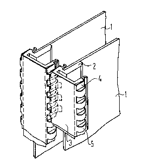
FIG. 1 is a per~pective view of a part o~ two
neighboring asse~blies having front covers and shrouds;
and
FIG. 2 i~ a plan view of the p~rts of FIG. 1.

2 1; ~
DESCRIPTION OF THE PREFER~ED EMBOa~MæNT
According to Figures 1 and 2, two electrical
assemblies are inserted into a magazine (not shown).
The assemblies have printed circuit boards 1 to whose
fro~t ~ides are attached front cover3 2 which are formed
of plastic. Shrouds 3 are snapped onto the ~ront covers
2. Shrouds 3, that are essantially bent into a u-shape
have retaining tabs 4 and contact ~abs 5 in alternating
succession on each of their long sides, these retaining
tabs 4 and contact tabs ~ having been produced by
shearing and differen bending. The contact tabs 5
thereby project beyond th~ retaining tabs 4. The t~b~
5 are mirror-symmetrically arranged on both long sides
of th~ shroud 3.
The shroud 3 extends over the entire length and
width of the ~ront cover 2. The contact tabs 5 are
contacted by contact tabs 5 of a neighboring assembly.
As result, the ~ntire ~ront side cf the fully equipped
magazine is covered in ~ealed r~d~o-frequency ~a~hion.
The retaining tabs 4 ~re perpendlcular to the ~ront
side o~ the assembli~s. The ~ree end of each ~f the
retaining tabs 4 is bent toward the front cover 2 and
engages behind the front cover 2 at a correspondiny latch
shoulder 6. The ~ront cover 2 i~ provided with lateral
leading ~evel~ 7 or ~he retaining tabs 4~
~ he contact tabs 5 are bent ~emicirGularly back onto
themselv~s and pro~ect ~eyond the front covers 2 in the
direction of the neighboring front covers to such an
extent that they press resiliently against the contact
tabs of the neighboring ~hrouds 3. A large-area contact

2 ~ 7
between the shrouda 3 i thu~ established due to the
multi~ude of contact tabs 5.
If the contact tabs 5 o~ one shroud 3 and the
retaining tabs 4 of the neighboring shroud 3 are
staggered relative to one another (as can be derived from
FIG. 1), then the contact tabs 5 of the one shroud 3 will
contact the retaining tab~ 4 of the neighboring shroud
3. The retaining tabs 4 then become contact locations
which are non-resilient.
The invention is not limited to the particular
details of the apparatus depicted and other modifications
and applications are contemplated. Certain other changes
may be made in the above described apparatus without
departing from the ~rue spirit and scope o~ the invention
herein involved. It is intended, therefore, that the
subject matter in the above depiction shall be
interpreted as illustrative and not in a limitiny sense.

Dessin représentatif
Une figure unique qui représente un dessin illustrant l'invention.
États administratifs

2024-08-01 : Dans le cadre de la transition vers les Brevets de nouvelle génération (BNG), la base de données sur les brevets canadiens (BDBC) contient désormais un Historique d'événement plus détaillé, qui reproduit le Journal des événements de notre nouvelle solution interne.

Veuillez noter que les événements débutant par « Inactive : » se réfèrent à des événements qui ne sont plus utilisés dans notre nouvelle solution interne.

Pour une meilleure compréhension de l'état de la demande ou brevet qui figure sur cette page, la rubrique Mise en garde , et les descriptions de Brevet , Historique d'événement , Taxes périodiques et Historique des paiements devraient être consultées.

Historique d'événement

Description Date
Inactive : CIB de MCD 2006-03-11
Le délai pour l'annulation est expiré 1998-06-08
Demande non rétablie avant l'échéance 1998-06-08
Inactive : Abandon.-RE+surtaxe impayées-Corr envoyée 1997-06-09
Réputée abandonnée - omission de répondre à un avis sur les taxes pour le maintien en état 1997-06-09
Demande publiée (accessible au public) 1990-12-09

Historique d'abandonnement

Date d'abandonnement Raison Date de rétablissement
1997-06-09
Titulaires au dossier

Les titulaires actuels et antérieures au dossier sont affichés en ordre alphabétique.

Titulaires actuels au dossier
SIEMENS AKTIENGESELLSCHAFT
Titulaires antérieures au dossier
EDUARD MAIR
INGEBORG BUSSE
PETER SEDLMEIER
Les propriétaires antérieurs qui ne figurent pas dans la liste des « Propriétaires au dossier » apparaîtront dans d'autres documents au dossier.
Documents

Pour visionner les fichiers sélectionnés, entrer le code reCAPTCHA :


Pour visualiser une image, cliquer sur un lien dans la colonne description du document. Pour télécharger l'image (les images), cliquer l'une ou plusieurs cases à cocher dans la première colonne et ensuite cliquer sur le bouton "Télécharger sélection en format PDF (archive Zip)" ou le bouton "Télécharger sélection (en un fichier PDF fusionné)".

Liste des documents de brevet publiés et non publiés sur la BDBC .

Si vous avez des difficultés à accéder au contenu, veuillez communiquer avec le Centre de services à la clientèle au 1-866-997-1936, ou envoyer un courriel au Centre de service à la clientèle de l'OPIC.


Description du
Document 
Date
(aaaa-mm-jj) 
Nombre de pages   Taille de l'image (Ko) 
Abrégé 1990-12-08 1 18
Revendications 1990-12-08 5 158
Dessins 1990-12-08 1 17
Description 1990-12-08 6 221
Dessin représentatif 1999-07-26 1 10
Courtoisie - Lettre d'abandon (taxe de maintien en état) 1997-09-01 1 188
Courtoisie - Lettre d'abandon (requête d'examen) 1997-09-01 1 173
Taxes 1996-05-22 1 85
Taxes 1995-05-16 1 87
Taxes 1994-05-12 1 69
Taxes 1993-05-19 1 49
Correspondance 1993-08-09 1 25
Taxes 1992-05-10 1 43