Note : Les descriptions sont présentées dans la langue officielle dans laquelle elles ont été soumises.
20~94~~
10
IMPROVED CROP PROCESSOR
Field of Invention
This invention relates to apparatus for processing
crops and particularly for cutting, conditioning, and
ZO windrowing standing crops such as hay and grasses and
for cutting standing crops such as corn and sorghum and
compressing and feeding such crop to a second crop
processing device such as a forage harvester,
Z5 Prior Art
The desirability of auger cutters to cut standing
crops has previously been recognized, Such cutters are
efficient and generally less susceptible to jamming or
plugging than the well-known sickle bar type of cutter)
30 Prior art crop processors include many devices showing
auger type cutters of various configurations for
various purposes. A prior art cutter or processor
developed especially for use with hay is shown and
described in U.S. Patent No. 4,550,554. Prior art
35 cutters for hay had cutting and handling disadvantages
and als o could not adequately cut and handle large
CA 02019449 1999-OS-19
- 2 -
crops such as corn. The cutting mechanism of this
invention has been improved in both cutting and
handling over the prior art. The crop transfer
mechanisms included in this processor are also advanced
over the crop processor shown in U.S. Patent No.
4,550,554 and the references cited therein.
A principal'object of this disclosure is to provide
an auger cutter that will cut standing crop of hay,
condition the crop as it is cut to speed the drying
process without loss of nutrient value and that will
position the crop in windrows for drying and further
handling. Another principle object is
to provide an auger cutter that will cut a standing
crop such as corn or sorghum and corn press the crop
and feed the crop after compression into the entrance
~of a second crop processor such as a forage harvester
without loss of crop and at a very rapid rate. Other
objects are to provide improved cutting and handling of
the crop whether it be hay or corn by utilizing
improved cutting mechanisms on an auger cutter and to
provide improvement in the feeding mechanisms and
discharge mechanisms to feed either the cut crop . or a
compressed cut crop from the crop processor.
The principal features here disclosed include a
cutter assembly having an auger cutter with a central
tubular shaft and auger flights extending therearound.
The auger flights are formed from a flange that is
helical around the central shaft and the direction of
rotation of the helix is reversed at a selected point
on the tube. The cut crop is discharged through an
opening in the central area of the processor and in the
case of hay is allowed to drop onto the ground in a
2Q1944~
windrow. Cutting teeth are attached to the flighting
near the peripheral outer edge to cut the standing crop
at the base of the stalks. The teeth of a novel design
are attached in a variety of ways depending upon the
crop to be cut and the amount of conditioning which is
desired to be accomplished with the crop. The teeth
project inwardly or outwardly and in the same direction
as the flange of the helix to which they are attached.
A plurality of conveying augers are positioned to
receive the crop cut and conditioned by the cutting
auger and to convey the crop to a central discharge
area for discharge either onto the ground or into a
second crop processor depending upon the crop and the
ultimate usage of the crop as determined by the desire
of the operator. The conveying auger is provided with
smooth surface flights formed from a helically wound
flange. The rotational speed of the conveying auger is
considerably less than the rotational speed of the
cutting auger when the cutting auger is being used to
cut a crop. There is a central discharge area between
the ends of the two conveying augers to provide for the
exiting of the crop onto the ground or into the second
crop processor.
A support frame carries the cutter auger, the
conveyor auger, the drive mechanisms for all augers,
and a forward top cover that engages the crop at a
preset height to properly angle the crop into the
cutter. The top cover cooperates with the conveyor
augers to move the crop centrally to the discharge
opening and a ground engaging roller provides for
height sensing and control and assists in supporting
the processor as it travels over the ground.
In one embodiment of the invention, the support
frame also carries a power discharge means in the
center, discharge area which simultaneously compresses
and conveys the crop material upwardly and outwardly
' .~ CA 02019449 1999-OS-19
- 4 -
.. from the crop processor and forces ,the crop into the
grasping rolls or entrance of a second crop processor.
Also in one embodiment of the invention, a third auger
means is attached to the front of the front cover and
is designed to force the crop, before cutting, toward
the center of the crop processor. This auger normally
has a more tightly wound helix, rotates at a relatively
slow rate as compared with the auger cutte r, prevents
material from escaping the cutter and ensures that the
crop proceeds as rapidly as possible to the center
discharge area.
In accordance with a first aspect of the invention there
is provided, a crop processor comprising:
a support frame coupled to a prime mover;
a drive system for said processor connected to and
powered from said prime mover;
at least two conveyor augers on a common axis,
each including a helical flange thereon, each conveyor
auger supported in cantilever fashion on said support
frame at opposite ends thereof, each of said conveyor
augers being less than half the width of the processor,
the helical flange of each conveyor auger wound to move
the material toward the center of the processor;
conveyor auger housings cooperating with said
conveyor augers to move the material
at least two cutting augers on a common axis;
support means for each of said cutting augers at
the ends and at the center of the processor;
each of said cutting augers having a helical
flange therearound with the flange from the outside .
3~ turned in the same direction as the conveyor flange for
at least a portion of the length of the coweyor auger
and a continuation reversely turned flange for the
remaining length of the cutting auger to the center of
the processor;
each of said flanges including a plurality of
first means for mounting cutting teeth thereon;
.~ CA 02019449 1999-OS-19
- 4a -
a plurality of cutting teeth;
second means for mounting each of said cutting
teeth to a single one of said first mounting means on
said flanges;
a front cover means pivotally attached to said
support means;
a baffle means attached to and extending from said
conveyor auger housing enlarging the volume for
conveying the cut crop;
a center discharge area to discharge cut crop to
the rear of said processor;
means for selecting and maintaining the height of
the cutting augers above the ground; and
whereby the crop is cut by the cutting augers and
fed by the conveying augers to the center area for
discharge.
In accordance with a second aspect of the invention
there is provided, a crop processor comprising:
a support frame coupled to a prime mover;
a drive system for said processor connected to and
powered by said prime mover;
a second crop processor integral with said prime
movers;
a first crop processor including;
at least two conveyor augers on a common axis,
each including a helical flange thereon, each conveyor
auger supported in cantilever fashion on said support
frame at opposite ends thereof, each of said conveyor
augers being less than half the width of the processor,
the helical flange of each conveyor wound to move the
material toward the center of the processor;
at least two cutting augers on a common axis,
support means for each of said cutting augers at the ends
and at the center of the first crop processor,
' CA 02019449 1999-OS-19
- 4b -
each of said cutting augers having a helical flange
therearound with the flange from the outside turned in the
same direction as the conveyor flange for at least a portion
of the length of the conveyor auger and a continuation
reversely turned flange for the remaining
length of the cutting auger to the center of the
processor;
each of said flanges including a plurality of
first means for mounting cutting teeth thereon;
a plurality of cutting teeth;
second means for mounting each of said cutting
teeth to said first mounting means on said flanges;
a front cover means pivotally attached to said
support means;
a baffle means attached to and extending from said
bottom housing enlarging the volume for conveying the
cut cr-op;
a center discharge area to discharge cut crop to
the rear of said processor;
a power discharge means in said center discharge
area ~to compress and force the material cut by the
first crop processor from said central discharge area; and
means for selecting and maintaining the height of
the cutting augers above the ground, whereby the crop
is cut by the cutting augers and fed by the conveying
augers to the center for discharge.
In accordance with a third aspect of the invention there
is provided, a crop processor comprising:
an auger having f lighting therearound;
support means for said auger;
drive means for rotating said auger;
teeth for attachment to said flighting on said
auger; and
CA 02019449 1999-OS-19
- 4c -
means for attaching said teeth to said f lighting,
each of said teeth including a metal base plate of
essentially horse shoe shape, having a circular portion
and converging side portion, a hole toward the circular
end of said base plate for attaching to said auger
flighting, said base plate having bevels on a major
portion of a first flat surface, the base plate being
bent in the direction of said first flat surface, and
the second flat surface of the base plate being hard
surfaced only on the converging side portion.
Fig. 1 is a side view of the crop processor embodying
.this invention attached to a forage harvester which
includes a second crop processor.
Fig. 2 is a sectional view taken on the line 2-2
of Fig. 1.
Fig. 3 is a top view of the crop processor.
Fig. 4 is a rear view of the crop processor
showing the discharge
openings and~tbe
roller elements)
Fig. 5 is a sectional view of Fig. 3 taken on the
line 5-5.
Fig. 6 is a sectional view taken on the line 6-6
of Fig. 4.
Fig, 7 is an exploded view of the frame including
cover units and
baffle plate.
Fig. 8 is a view of the cutter auger showing the
helixes thereon,
Fig, 9 is a sectional view through line 9-9 of
Fig. 8.
Fig. 10 is a sectional view taken on the line
10-1~0 of Fig. 8,
CA 02019449 1999-OS-19
_ 5
Figs. 11, 12, 13 and 14 show the attachment of the
teeth to the flighting of the cutting auger.
Fig. 15 is a sectional view along line 15 of Fig,
14.
Fi.g) 16 is a side view of the power auger
assembly.
Detailed Description of a Preferred
Embodiments of the Invention
Referripg.now tp the drawings: in the illustrated
embodiment of the invention the crop processor is shown
generally at 10. The crop processor includes the auger
cutter and the other operating elements of the crop
processor. The crop processor is shown attached to a
prime mover and second processor shown as a forage
harvester 11. The crop processor 10 includes a support
frame 12 shown best in Fig. 7 comprising a rear top
rail l3 formed from a rectangular tube and having end
plates 18 and 19 and a center plate 17. There is a
bottom front rail 15 and a front top rail 14 which are
an integral part of the frame and are connected by
. support members 16 between the front top rail 14 and
the bottom front rail 15. The end plates 18 and 19 are
firmly fixed to the support frame 12 at the ends
thereof. In addition, there is shown in Fig. 7 the
bearing units 20 and 21 which are fitted into the holes
22 in the end plates 18 and 19. Also shown in Fig. 7
are the conveyor auger bottoms 23, the conveyor cover
24 from rear to the top for the conveyor augers 27, the
side plates 24a to close off the exit for the central
discharge area. There is also shown~the baffle plate
25 in Fig, 7. Fig. 7 shows the support for the drive
unit to drive the power discharge units. This plate is
numbered 26. The open, generally central discharge
area .is designated as 30 and is seen very clearly as an
open area in Fig. 7,
X019449
- 6 -
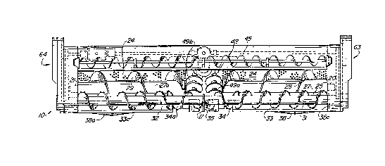
As seen in Figs. 2, 3 and 4, a pair of .cutting
augers shown generally at 31 and 32 extend between the
end plates 18 and 19. Each auger has a shaft that is
journalled at the respective end plate and at the
center plate 17 for rotation and is driven by pulleys
and drive belts exterior to the end plates shown
generally in the enclosures 63 and 64. The pulley
drive units and the belts associated therewith are not
shown in detail but are the kind well known to those
skilled in the art. The cutter augers have oppositely
turned helical flanges 33 and 33a to move the material
toward the center or discharge area. There are
reversely turned flanges 34 and 34a at or near the
discharge area which are turned out of end plates 35
and 35a. The cutting augers 3i and 32 are so located
that their central axes are parallel to the central
axes of the conveying augers and are spaced therefrom
.so that adequate clearance is provided between the
helical flanges of the two sets of augers. A plurality
of teeth 37 to be further described are attached to and
project around the peripheral edges of the flange
plates 34, 34a, 35, and 35a. The cutter augers are
beneath and forward of the conveyor augers during
travel of the unit 10 in the cutting and processing of
standing crops.
In prior auger cutting devices plates have been
used between the cutting augers and the conveying
augers to guide material into the conveying auger.
Such a cover plate is described in U.S. Patent No.
4,550,554, Column 4, lines 48 through 55. Such a plate
has previously permitted both crop accumulation on the
plate and ejection forward of the crop material
collected in the conveyor auger housing.
It has been found that the shape and locations of
this plate is critical to proper operation of the
processor. The upper edge of the baffle plate must be
~0~~~4~
_,_
placed in close proximity to the cutting auger and the
best operation has been with the plate being located
not more than 0.5 inches from the teeth of the cutting
auger, yet not impacting the teeth. The baffle plate
must also be shaped between the radius of the cutting
auger or the conveyor auger for best operation.
A pair of ground engaging rollers 38 arid 38a are
each controlled by an independent mechanism which
allows each side of the processor to be raised or.
lowered by some predetermined amount independently of
each other. These rollers must have sufficient surface
area to support at least a portion of the weight of the
processor. Thel processor is raised and lowered by the
hydraulic system of the prime mover and in most
instances this system will be able to support a portion
of the weight of the processor. The rollers 38 and 38a
have a tapered design which allows the roller to clean
.itself as it rolls. The tapered design also permits
turning corners with a minimum disturbing of the soil.
The cleaning action results from new material being
picked up, forcing already adhered material to be
pushed along the taper and out toward the outward ends
of the roller. The adhesion between the soil or other
material and the roller surface is also weakened by any
lateral movement of the processor until the material
finally drops off the end. By having the tapered
design, most of the wear occurs at the center of the
roller and this area can be easily hardened for longer
wear. The rollers are connected to the bottom support
member 16 by plates 42 which permit the pivoting about
the center point of the roller 38 as shown in Fig. 6.
The roller is attached to the plate 42 via bars 42a
which are connected to hydraulic cylinders 39 which are
connected to switch means 41 in such a manner that when
the ground engaging rollers 38 or 38a are on the
ground, pressure is applied to the cylinder 39 closing
~o~s~~~
_a_
the switch 41. This moves front door 43 to the
operating position and can inform the operator that the
unit is on the ground. The height of cut is maintained
by this roller switch mechanism acting in conjunction
with the hydraulic cylinder 39. The tilt and selected.
cutting height of the processor can be set by the
operator from the main control as the speed, crop
conditions, and/or contour of the land changes.
There is a further important part of the processor
which is shown in Fig. 6, the door or front cover unit
43. This front cover unit 43 is pivotally hinged about
the upper main frame 14 and is pivoted by controlling
the cylinders 44., The height of the front door unit
43 above the ground should be adjusted by the operator
to ensure that the grass or material to be cut is bent
forward the proper amount just prior to being hit by
the teeth of the cutting auger. This height will vary
-depending upon the nature and density of the crop to be
cut.
It has been found that in large standing crops
such as corn where the material is not to be windrowed
but to be fed to a second unit such as a forage
harvester, and additional crop moving auger 45 should
be attached to the front of the door 43. This crop
moving auger ensures that the crop enters the processor
and is not lost to the sides as the processor moves
through the crop. The crop moving auger 45 as shown in
Fig. 3 has a plurality of smooth flightings attached to
it. These flightings are helical flanges 46. These
helical flanges may be variable and indeed different
conditions may require different pitches per foot along
the entire auger length. These flanges are wound to
move the crop toward the center from each side. It may
be necessary in order to determine the proper speed
that this auger 45 have variable speed drive. This
auger therefore is driven by a hydraulic drive 47 which
~01944~
_ g _
can be controlled from the cabin by the operator. This
auger normally rotates at a much lower speed than the
cutting auger. This speed can be controlled and has
little relationship to the speed of the crop conveying
auger but is closely related to the ground speed of the
processor.
The front door must have an automatic control to
ensure that during transport whenever the augers are
rotating the front door is closed. This automatic
door operation can be accomplished by either
determining the pressure of the prime mover's hydraulic
system with pressure switches or by monitoring the
position of the.tapered rollers. This latter method is
shown in Fig. 6a where the upward movement of the
hydraulic cylinder 39 will cause operation of the limit
switch 41. Either roller can operate the door based
upon whether or not the roller is in a down position.
.If either roller 38 or 38a is on the ground, this
forces the limit switch 41 to be operated and the door
is returned to a predetermined operating position. If
neither roller of the processor is in contact with the
ground, the limit switches 41 are opened and door will
automatically be lowered into the transport or safety
closed position.
When processing corn or sorghum which is to be fed
into a second crop processor, namely, a forage
harvester, an entirely different set of problems arises
and requires further novel features of this processor.
Namely, the push augers or the feed augers 48 which are
positioned in the central discharge area 30) These
augers may be installed as a removable unit or may be
permanently installed in such area. The necessity to
force-feed large quantities of material which have been
cut by the crop processor into a second processor
requires this plurality of feed augers 48. These
augers can feed 12 feet or more of crop material
2~~.~44~
- 10 -
forcefully out of the crop processor .into a relatively
small exit area. These augers serve to compact the
material and force the material under extreme pressure
from the crop processor into whatever other processor,
or unit is required to finish the crop processing. The
material enters from the side of the conveying auger 27
and 27a into the lower feed augers 49a arid 49b. These
units have their radially turned flanges directed
inwardly and upwardly. The upper auger 50 acts to both
compress the crop between the augers 49a and 49b and to
feed the crop to the rear of the crop processor. These
augers are each placed to form a three sided pattern
which terminates at the exit of the processor or the
entrance to the next unit.
This feeding mechanism requires a novel header
mounting which will be described more fully later, but
one that ensures that the feed augers 49a, 49b and 50
.are never more than three inches from the entrance
augers or grab rolls of the second crop processor. The
V-shape of the feed auger unit allows material to enter
from either the cutting auger directly or from the
cutting auger via the conveyor augers. The conveyor
augers move the material toward the feed augers and,
under pressure, force the material into the V-shape of
the feed augers. The flighting on the augers is such
that the material is moved upwardly and inwardly for
compression by auger 50 and movement rearwardly for
discharge. The power feed augers 49a and 49b in
operation are subjected to extreme lateral forces as
the large mass of material is fed from the conveying
augers into the discharge area. Normal auger mountings
failed every time during experimental use and such
failure was almost immediate.
The novel auger module was able to withstand all
loads during development. The design shown is a
modular unit though the entire auger assembly could be
2~~.~449
- 11 -
one unit. The auger assembly consists of flighting
49a'; a slightly heavier than the usual flighting of a
conveyor auger, flighting tube 49a, auger support
plates 77 and auger support shaft 78. A coupler 72 is
used to transmit the necessary torque to the auger.
Radial loading is absorbed by bearings 73. A spacer
75, or~ a plurality of spacers may be used to transfer
the thrust load to either or the gear box 71 and
bearings 73.
Means such as pins not shown, may also be used to
retain both bearing 73 and to lock coupler 72 to shaft
78 thereby retaining the auger assembly in position.
The drive system for these augers consists of a
T-shaped gear box 52 attached to a chain box 57a which
may contain an overload safety device which can be
provided by an overload clutch, of any well known type
not shown. The lower feed augers 49a and 49b receive
.their power from the top shaft power source by a belt
series to shaft 53. Shaft 53 is carried inside of the
main support frame 12 to provide protection from
wrapping of material on the shaft.
In this mode of operation, i.e., heavy corn, or
Where the central discharge area is occupied by a large
mass of solid material, provision should be made for
releasing the air generated by the rotation of the
cutting and conveying augers in the enclosed space.
This air pressure should be released in order for
the system to operate efficiently. The air pressure is
released in one embodiment of this invention by
providing screen means in the top cover 24 and the
sides 29a of the discharge openirig. The means 24 and
24a are made of a suitably strong screen material which
has approximately 50 percent openings and 50 percent
material. The holes in the material should be small
enough so that alfalfa leaves or small parts of oats
will not pass through the holes and also provide that
CA 02019449 1999-OS-19
- 12 -
the conveyor and feed augers wipe over the screen.
This wiping should ensure that the screen will be
completely cleaned approximately every three
revolutions of the conveyor auger. This provides for
both the release of the air and the capture. of all of
the material.
The mounting system is best
illustrated in Fig. 5. The mounting system for this
crop processor requires that the head or first crop
processor has the ability to tilt relative to the
second processor. The controls for this tilt are
located in the cab, allowing the operator to change the
cutting height while moving. It also has been found
necessary during tilting of the first processor to
prevent any gaps forming between the output means of
this processor and the input means to the power source
or second processor. The mounting system must also
provide means to limit movement of the terminal end of
the feed augers away from the input side of the second
processor. In addition, the header or first processor
as has been previously mentioned must be able to flex
up and down on either side with respect to the prime
mover and also permit the rollers previously mentioned
to traveh over a rise in the ground on only one side
without stressing the mounting system. The mounting
system should be such that attachment and removal are
easily accomplished,
The mounting system is provided
by having a frame 55 attached to the chopper head or
the second processor head by pins 56 at the four
corners. In addition, there are two plates 54 welded
to the frame. These plates provide a U-shaped slot on
each side of the discharge opening in the processor.
The axis of rotation between this frame and the header
of the second processor is such that it is centered
around the upper corner of the lower frame member of .
CA 02019449 1999-OS-19
- 13 -
the attached second processor. The force for rotation
is provided by two cylinders 57 which is at the lower
point 56. The movement of the cylinders is controlled
from the cab and can forcefully tilt the header through
the frame member and its connection to the lower
support frame member 16.
Another operational aspect embodied in this invention is
that in many instances the forage harvesters or the
second crop harvesters have metal detectors in their
chopping unit to stop the forage operation as soon as
metal is detected. If metal is detected, the second
processor ceases to operate and if material were
continued to be fed from the first crop processor, then
a jam would occur as there is no place for the cut
material to go. In addition, because of the great
pressures exerted by the power auger feed system
against a fixed surface an intolerable plug would
result. To prevent this plugging, a throw out coupler
system has been utilized to protect and stop the power
input to the second crop processor. The metal
detection system is located in the second crop
processor and if it senses metal it generates an
electrical signal which stops the second crop processor
operation. This same electrical signal is connected to
the throw out coupler system in the first processor.
The power source 61 from the prime mover 11 is
connected to the first gear box 58 of the crop
processor by pto shaft 60. This will permit flexing
and relative movement between the prime mover unit and
the header or the first crop processor. A throw out
coupler system 59 is placed between the~gear box 58 and
the gear box 62 so that the power will immediately be
cut by the throw out coupler when the power is cut to
the feed system of the prime mover unit.
. The teeth 37 used on this crop processor are
unique and are best described with reference to Figs.
-- 14 -
11, 12, 13, 14 and 15. The teeth incorporate several
features to give the teeth long operational life,
impact resistance, versatility, etc. The tooth, of
generally horse shoe configuration shown in Fig. 15 in
plan view, includes a beveled surface 37a, a hole 37c
for mounting the tooth and a flat surface 37b, and the
other side is flat surface 37b'. A portion of surface
37b' and the bevel surface at the converging end has a
layer of hardened material applied to make surface 37b'
the wear and self-sharpening characteristics of the
tooth. The tooth is bent at approximately 45° in the
direction of the bevel surface. The mounting system
for this tooth provides for a plurality of mounting
configurations as shown in Figs. 11, 12, 13 and 14. In
Fig. 12, the tooth 37 is mounted by bolts 37d and nut
37e through the hole 37c in the tooth 37and the
flighting 33a. The cutting auger tube 32 is also
shown. In each of these figures the tooth is viewed
from the front as the tooth is ready to cut the crop
material. The mounting bolts have an angle similar to
the bevel 37a to provide a slope surface to prevent
sticking of the cut material and reduce wear on the
bolt. The tooth 37 is designed with a symmetrical
pattern. The symmetry results in two cutting edges on
each tooth. When one edge is worn down the tooth may
simply be reinstalled to a new position on either auger
of the machine so that the second cutting edge can be
used.
The characteristics of this tooth can be mounted
on the front side or the back side of the flighting as
shown in Figs. 11, 12, 13 and 14. As shown in Figs.
12, 13 and 14 a lock washer 37f is used to maintain the
tooth in a fixed position. This permits any fixed
cutting angle to be established as desired due to crop,
etc. ' The lock washer in Fig. 14 can be removed from
the bolt 37d to permit swinging of the teeth. The
~0194~~
_ 15 _
front side swinging mount as shown in Fig. 11 provides
the most aggressive cutting action and is useful in
most cutting situations. The tooth can also be mounted
on the backside of the flange as shown in Figs. 12 and
14; however, in Fig. 12 it must be rigidly mounted.
Backside mounting provides a less aggressive action and
is utilized in handling tender material. Where the
crop material is thicker and more rigid as in the case
of corn, front mounting in preferred.
As noted, the present disclosure is based on a
preferred embodiment of the invention. Features and
advantages other than those specifically pointed out
herein will occur to those versed in the art, as will
many modifications in the preferred embodiment
presented, all without departing from the spirit and
scope of the invention.
25
35