Sélection de la langue

Search

Sommaire du brevet 2019521 

Énoncé de désistement de responsabilité concernant l'information provenant de tiers

Une partie des informations de ce site Web a été fournie par des sources externes. Le gouvernement du Canada n'assume aucune responsabilité concernant la précision, l'actualité ou la fiabilité des informations fournies par les sources externes. Les utilisateurs qui désirent employer cette information devraient consulter directement la source des informations. Le contenu fourni par les sources externes n'est pas assujetti aux exigences sur les langues officielles, la protection des renseignements personnels et l'accessibilité.

Disponibilité de l'Abrégé et des Revendications

L'apparition de différences dans le texte et l'image des Revendications et de l'Abrégé dépend du moment auquel le document est publié. Les textes des Revendications et de l'Abrégé sont affichés :

  • lorsque la demande peut être examinée par le public;
  • lorsque le brevet est émis (délivrance).
(12) Brevet: (11) CA 2019521
(54) Titre français: LEVIER PERMETTANT LE REGLAGE DE LA CHAISE
(54) Titre anglais: HANDLE ASSEMBLY FOR CHAIR CONTROL MECHANISM
Statut: Périmé et au-delà du délai pour l’annulation
Données bibliographiques
Abrégés

Abrégé anglais


A chair control mechanism of the type having a seat
support member pivotally mounted on a leg mounting member, and a
spring loaded adjustment mechanism for controlling the pivotal
movement of one member with respect to the other. The adjustment
mechanism includes a handle mounted on an adjustment screw for
movement therealong to compress or allow extension of the
compression spring. A nut is threadedly mounted on the
adjustment screw and serves to retain the members, adjustment
screw and spring in an assembled configuration during shipping to
and assembly of a chair by a chair manufacturer. A hand wheel is
provided for attachment to the nut after the control mechanism
has been assembled and installed in a chair. The hand wheel has
a body of plastics material in which a seat formed which is
proportioned to accommodate and adapted to cooperate with the nut
such that when the nut is seated therein, rotation of the hand
wheel will cause rotation of the nut with respect to the
adjustment screw. The seat also cooperates with the nut to
prevent removal of the nut therefrom. The body of plastics
material is sufficiently flexible to permit resilient deformation
of the seat to admit the nut thereto.

Revendications

Note : Les revendications sont présentées dans la langue officielle dans laquelle elles ont été soumises.


THE EMBODIMENTS OF THE INVENTION IN WHICH AN EXCLUSIVE
PROPERTY OR PRIVILEGE IS CLAIMED ARE DEFINED AS FOLLOWS:
1. In a chair control mechanism of the type having a seat
support member pivotally mounted on a leg mounting member, and
means for controlling the pivotal movement of said members with
respect to one another including an adjustment screw, a
compression spring and a handle mounted on the adjustment screw
for movement therealong to compress or allow extension of the
compression spring, the improvement wherein the handle comprises:
a) a nut that is threadedly mounted on the adjustment
screw and serves to retain said adjustment screw and compression
spring to said seat support member and leg mounting member in an
assembled configuration, during shipping to and assembly of a
chair by a chair manufacturer, the nut having a plurality of side
faces and having an annular recess; and
b) a hand wheel comprising a body of a deformable and
resilient plastic material having a sleeve formed therein which
is proportioned to receive and cooperate with said nut, said
sleeve of said hand wheel having a bore extending therethrough
for receiving said nut, the sleeve having a plurality of side
faces bordering the bore, at least some of which are located
adjacent some of the side faces of said nut to prevent
substantial rotational movement of the nut with respect to the
hand wheel and arranged to bear against at least a portion of the
- 10 -

side faces of the head of the nut during rotation of the hand
wheel to permit torque forces to be transferred from the hand
wheel to the nut such that when the nut is seated within said
sleeve, rotation of the hand wheel will cause rotation of the nut
with respect to the adjustment screw, the hand wheel provided
with detent means projecting into the bore from said sleeve, the
hand wheel, the sleeve and the detent means being of unitary
construction, the detent means being shaped and proportioned so
that during assembly, the hand wheel may be pushed over the nut
so that the nut is received by the bore in the sleeve and the
detent means resiliently deforms over the head portion of the nut
until the detent means extends into the annular recess of said
nut thereby preventing axial movement of the hand wheel relative
to the nut, said detent means by itself not restricting
rotational movement of the hand wheel relative to the nut.
2. A control mechanism according to claim 1 wherein said
detent means comprises at least two projections each located on a
different face bounding said bore, and wherein said nut is
provided with a tubular portion which extends axially from the
head portion, the annular recess being located in said tubular
portion and being circumferentially disposed thereabout.
- 11 -

Description

Note : Les descriptions sont présentées dans la langue officielle dans laquelle elles ont été soumises.

2ol9~l
04641-14/LCS
HANDLE ASSEMBLY FOR CHAIR CONTROL MECHANISM
FIELD OF THE INV~ lON
This invention relates to chair control mechanisms. In
particular, this invention relates to improvements in the
adjustment handle of a chair control mechanism.
BACKGROUND OF THE INV~llON
Chair control mechanisms are used to connect the leg of
a chair to a chair seat and in some cases to the backrest of a
chair such as the type of chair commonly referred to as an office
chair. These control mechanisms are manufactured and assembled
in a metal forming and stamping operation and commonly comprise a
seat support member that is pivotally mounted on a leg mounting
member and an adjustment screw, compression spring and handle
that cooperate with one another to preload the chair control
mechanism to control the movement of the seat support member with
respect to the leg mounting member.
For aesthetic purposes, it is common practice to paint
the handle so that it is colour coordinated with the colour of
the chair control mechanism or the colour of the fabric of the
chair in which the control mechanism is incorporated in use. The
manufacturer of chair control mechanisms frequently finds that
quality control complaints are received because the paint applied
to the handle is scratched or otherwise damaged during the

20~-~521
04641-14/LCS
assembly of the chair control mechanism and/or the shipping of
the control mechanism to the chair manufacturer or during the
assembly of the chair. As a result, the manufacturer of chair
control mechanisms generally produces a greater number of handles
than might otherwise be required in order to provide a ready
source of replacements.
To provide for the ease of manual manipulation, the
handle is generally quite large with the result that it is
susceptible to damage by contact with other objects during the
assembly of the chair control mechanism and the shipping and
handling of the preassembled control mechanism and the
installation of the control mechanism into a chair.
SUMMARY OF THE lNV~ ON
It is an object of the present invention to provide a
two-part handle for a chair control mechanism which will permit
the control mechanism to be preassembled using an element which
is subsequently covered by a second element which can be attached
to the first element after installation of the control mechanism
into a chair.
The subject invention provides a chair control
mechanism of the type having a seat support member pivotally
mounted on a leg mounting member. There is included means for
controlling the pivotal movement of said members with respect to
-- 2 --

2019S21
04641-14/LCS
one another including an adjustment screw, a compression spring
and a handle mounted on the adjustment screw for movement
therealong to compress or allow extension of the compression
spring. The improvement in the chair control mechanism comprises
a nut that is threadedly mounted on the adjustment screw which
serves to retain the adjustment screw and compression spring to
the seat support member and leg mounting member in an assembled
configuration, during shipping to and assembly of a chair by a
chair manufacturer. The nut has a plurality of side faces and
includes an annular recess. The improvement includes a hand
wheel comprising a body of a deformable and resilient plastic
material having a sleeve formed therein which is proportioned to
receive and cooperate with the nut. The sleeve of the hand wheel
has a bore extending therethrough for receiving the nut. The
sleeve has a plurality of side faces bordering the bore, at least
some of which are located adjacent some of the side faces of the
nut to prevent substantial rotational movement of the nut with
respect to the hand wheel and arranged to bear against at least a
portion of the side faces of the head of the nut during rotation
of the hand wheel to permit torque forces to be transferred from
the hand wheel to the nut such that when the nut is seated within
the sleeve, rotation of the hand wheel will cause rotation of the
nut with respect to the adjustment screw. The hand wheel is
provided with detent means projecting into the bore from the

2019~21
04641-14/LCS
sleeve. The hand wheel, the sleeve and the detent means are of
unitary construction with the detent means being shaped and
proportioned so that during assembly the hand wheel may be pushed
over the nut so that the nut is received by the bore in the
sleeve and the detent means resiliently deforms over the head
portion of the nut until the detent means extends into the
annular recess of the nut thereby preventing axial movement of
the hand wheel relative to the nut. The detent means by itself
does not restrict rotational movement of the hand wheel relative
to the nut.
BRIEF DESCRIPTION OF THE DRAWINGS
The invention will be more clearly understood after
reference to the following detailed specification read in
conjunction with the drawings wherein;
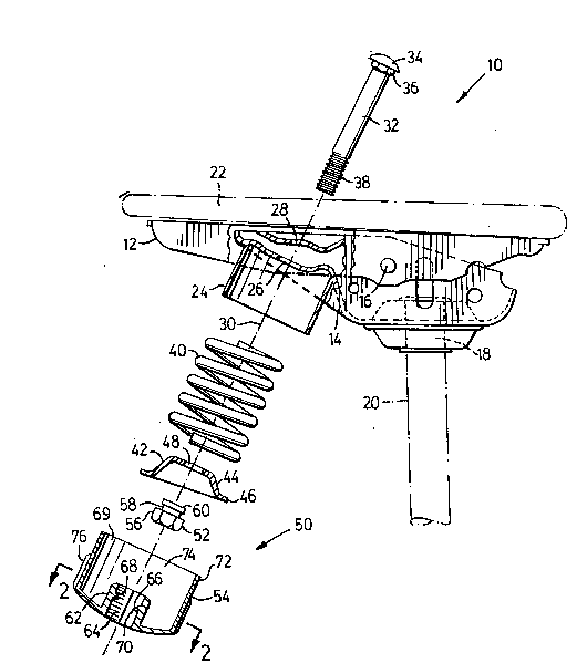
Figure 1 is a partially exploded side view of a chair
control mechanism constructed in accordance with an embodiment of
the present invention; and
Figure 2 is an end view of the hand wheel of Figure 1.
DETAILED DESCRIPTION OF THE l~V~ lON
With reference to the drawings, the reference numeral
10 refers generally to a chair control mechanism. The chair
control mechanism 10 includes a seat support member 12 which is
-- 4 --

~ O 19 ~ 21 04641-14/LCS
pivotally mounted on a leg support member 14 by means of a pivot
pin 16. A socket 18 is formed in the leg support member 14 to
receive a leg or support post 20 of a chair in use. The seat
support member serves to support a seat pad or cushion assembly
22. A collar 24 is mounted on the underside of a portion of the
back support member 14. Passages 26 and 28 are formed in the leg
support member 14 and the seat support member 12 and are aligned
with one another along the axis 30. Adjustment screw 32
comprises a coach bolt having an enlarged head 34 and a hexagonal
projection 36 which extends downwardly from head 34. A threaded
end portion 38 is located adjacent to the free end of the
adjustment screw.
A compression spring 40 is provided which is
proportioned to fit freely within the collar 24. A pressure
plate 42 is provided which serves to be against the spring 40.
The pressure plate 42 has a nub 44 that extends into the core of
the coil spring and a flange 46 that extends over the end of the
coil spring. Pressure plate 42 is provided with a passageway 48
extending therethrough of sufficient size to receive screw 32.
All of the structural elements described to this point
are conventional components of a chair control mechanism and have
not, therefore, been described in greater detail.

2019521
04641-14/LCS
The reference numeral 50 refers generally to a handle
which is a two-part handle that includes a small nut 52 and a
large hand wheel 54.
The small nùt 52 has a threaded bore (not shown) that
is proportioned to threadably engage the threaded end 38 of the
adjustment screw 32. The small nut 52 has a hexagonal head
portion 56 at one end thereof. An annular recess 58 is formed in
a tubular portion 60 which projects from the head 56.
The large hand wheel 54 is formed with a sleeve portion
62 which has a bore 64 that extends therethrough. The sleeve
portion 62 has detents 66 that project inwardly thereof into bore
64. The detents 66 have an inclined face 68 directed toward the
open end 69 of the hand wheel and a radially extending face 70
which forms a shoulder that is directed toward the opposite end
of the hand wheel. The bore 64 is hexagonal in cross section as
shown in Figure 2 of the drawing and is proportioned to receive
the head portion 56 of the nut in a close-fitting relationship.
The detents 66 are proportioned to extend into the annular recess
58 and serve to retain the large hand wheel 54 on the small nut
52.
The large hand wheel 54 also has a cap 72 which has a
bore 74. Ridges 76 are formed on the exterior face of the cap 74
and serve to provide finger gripping ridges which facilitate
manual engagement of the hand wheel for rotation thereof in use.

~019~2~
04641-14/LCS
The seat support member 12 and leg support member 14
are fabricated in the conventional manner and are pivotally
connected to one another by means of the pivot pin 16. The
adjustment screw 32 is mounted so that it extends through the
passages 26 and 28 and has its square projection 36 seated in the
uppermost passage 28 which is also a very square configuration to
receive the radial projection 36 and retain the bolt against
rotation. The compression spring 40 is seated in the collar 24.
The pressure plate 42 is also positioned over the end of the
spring 40 with the threaded end portion 38 of the adjustment
screw 32 extending through passageway 48. The small nut 52 is
then threadedly mounted on the threaded end 32. This assembled
chair control mechanism may be packaged and shipped to the chair
manufacturer without attaching handle 50 to small nut 52.
The handle 50 may be made from a plastics material and
may be an injected moulded handle. The handle 50 may be formed
from a plastics material which has a predetermined colour chosen
to coordinate with the colour scheme of the chair. The handles
may be shipped to the chair manufacturer separate from the
remainder of the chair control mechanism or they may be
separately packaged in a protective covering and shipped one with
each chair control mechanism.
When the chair control mechanism is received by the
chair manufacturer which may be within the same manufacturing

2019~21
04641-14/LCS
organization as that which produces the chair control mechanism
or it may be a distinctly different manufacturing company. When
the chair control mechanism is received, it is assembled to form
a chair by attaching a seatpad 22 and leg 20 and other structural
components such as a backrest support all in a conventional
manner. All of this assembly can be carried out without a need
to attach the handle to the small nut 52. Once the chair has
been assembled, the handle 50 may then be attached to the small
nut 52. This can be achieved simply by forcing the bore 64 of
the handle over the hexagonal-shaped head portion 56 of the small
nut until the detents 66 enter the annular recess 58. The
inclined faces 68 of the detents serve to facilitate the passage
of the large head portion 56. Once the handle 50 has been
mounted on the nut 52, rotation of the handle 50 will cause
rotation of the nut 52 to adjust the pressure applied by the
compression spring 40 in a conventional manner. It will be seen
that by delaying the final step of assembly of the handle 50 it
is possible to avoid damaging the surface finish of hand wheel 54
during the initial assembly of the chair control mechanism and
during the installation of the chair control mechanism in a
chair. It will be understood that hand wheel 54 may also be
painted to provide the required colour coordination. The fact
that it is possible to delay the mounting of hand wheel 54 on to
small nut 52 until the remainder of the assembly has been
-- 8

2919521
04641-14/LCS
completed also serves to ensure that a paint finish is not
damaged during the prior assembly procedures.
From the foregoing, it will apparent that the handle
assembly of the present invention serves to reduce the likelihood
of damage to the surface finish of the adjustment handle in
advance of the point of sale of the assembled chair.

Dessin représentatif
Une figure unique qui représente un dessin illustrant l'invention.
États administratifs

2024-08-01 : Dans le cadre de la transition vers les Brevets de nouvelle génération (BNG), la base de données sur les brevets canadiens (BDBC) contient désormais un Historique d'événement plus détaillé, qui reproduit le Journal des événements de notre nouvelle solution interne.

Veuillez noter que les événements débutant par « Inactive : » se réfèrent à des événements qui ne sont plus utilisés dans notre nouvelle solution interne.

Pour une meilleure compréhension de l'état de la demande ou brevet qui figure sur cette page, la rubrique Mise en garde , et les descriptions de Brevet , Historique d'événement , Taxes périodiques et Historique des paiements devraient être consultées.

Historique d'événement

Description Date
Inactive : CIB désactivée 2019-01-19
Inactive : CIB du SCB 2018-01-27
Inactive : CIB expirée 2018-01-01
Lettre envoyée 2008-01-10
Lettre envoyée 2007-10-29
Inactive : CIB de MCD 2006-03-11
Lettre envoyée 2005-10-13
Le délai pour l'annulation est expiré 2003-06-23
Lettre envoyée 2002-06-21
Lettre envoyée 2002-05-01
Inactive : Demande ad hoc documentée 2002-04-30
Inactive : Correspondance - Transfert 2002-04-11
Lettre envoyée 2002-03-12
Inactive : Lettre officielle 2002-03-12
Lettre envoyée 2002-03-12
Inactive : Transferts multiples 2002-01-30
Accordé par délivrance 1994-11-15
Toutes les exigences pour l'examen - jugée conforme 1992-11-20
Exigences pour une requête d'examen - jugée conforme 1992-11-20
Demande publiée (accessible au public) 1991-12-21

Historique d'abandonnement

Il n'y a pas d'historique d'abandonnement

Historique des taxes

Type de taxes Anniversaire Échéance Date payée
TM (brevet, 8e anniv.) - générale 1998-06-22 1998-05-19
TM (brevet, 9e anniv.) - générale 1999-06-21 1999-05-18
TM (brevet, 10e anniv.) - générale 2000-06-21 2000-06-02
TM (brevet, 11e anniv.) - générale 2001-06-21 2001-06-04
Enregistrement d'un document 2002-01-30
Titulaires au dossier

Les titulaires actuels et antérieures au dossier sont affichés en ordre alphabétique.

Titulaires actuels au dossier
LEGGETT & PLATT LTD.
Titulaires antérieures au dossier
WILLIAM S. STUMPF
Les propriétaires antérieurs qui ne figurent pas dans la liste des « Propriétaires au dossier » apparaîtront dans d'autres documents au dossier.
Documents

Pour visionner les fichiers sélectionnés, entrer le code reCAPTCHA :


Pour visualiser une image, cliquer sur un lien dans la colonne description du document (Temporairement non-disponible). Pour télécharger l'image (les images), cliquer l'une ou plusieurs cases à cocher dans la première colonne et ensuite cliquer sur le bouton "Télécharger sélection en format PDF (archive Zip)" ou le bouton "Télécharger sélection (en un fichier PDF fusionné)".

Liste des documents de brevet publiés et non publiés sur la BDBC .

Si vous avez des difficultés à accéder au contenu, veuillez communiquer avec le Centre de services à la clientèle au 1-866-997-1936, ou envoyer un courriel au Centre de service à la clientèle de l'OPIC.

({010=Tous les documents, 020=Au moment du dépôt, 030=Au moment de la mise à la disponibilité du public, 040=À la délivrance, 050=Examen, 060=Correspondance reçue, 070=Divers, 080=Correspondance envoyée, 090=Paiement})


Description du
Document 
Date
(aaaa-mm-jj) 
Nombre de pages   Taille de l'image (Ko) 
Abrégé 1994-11-14 1 33
Description 1994-11-14 9 298
Revendications 1994-11-14 2 73
Dessins 1994-11-14 1 31
Dessin représentatif 1999-07-13 1 22
Courtoisie - Certificat d'enregistrement (document(s) connexe(s)) 2002-03-11 1 113
Avis concernant la taxe de maintien 2002-07-21 1 177
Correspondance 2002-04-30 1 10
Correspondance 2002-03-11 1 13
Correspondance 2005-06-22 1 19
Correspondance 2005-10-12 1 11
Correspondance 2007-10-28 1 16
Correspondance 2008-01-09 1 12
Correspondance 2007-11-20 2 51
Taxes 1994-06-13 1 51
Taxes 1997-05-19 1 80
Taxes 1996-05-16 1 74
Taxes 1995-05-13 1 69
Taxes 1993-06-16 1 45
Taxes 1992-05-13 1 42
Correspondance de la poursuite 1992-11-19 1 51
Correspondance de la poursuite 1992-11-29 4 94
Courtoisie - Lettre du bureau 1992-12-20 1 43
Courtoisie - Lettre du bureau 1993-04-01 1 17
Correspondance reliée au PCT 1994-08-29 1 56
Courtoisie - Lettre du bureau 1990-11-18 1 60