Sélection de la langue

Search

Sommaire du brevet 2019540 

Énoncé de désistement de responsabilité concernant l'information provenant de tiers

Une partie des informations de ce site Web a été fournie par des sources externes. Le gouvernement du Canada n'assume aucune responsabilité concernant la précision, l'actualité ou la fiabilité des informations fournies par les sources externes. Les utilisateurs qui désirent employer cette information devraient consulter directement la source des informations. Le contenu fourni par les sources externes n'est pas assujetti aux exigences sur les langues officielles, la protection des renseignements personnels et l'accessibilité.

Disponibilité de l'Abrégé et des Revendications

L'apparition de différences dans le texte et l'image des Revendications et de l'Abrégé dépend du moment auquel le document est publié. Les textes des Revendications et de l'Abrégé sont affichés :

  • lorsque la demande peut être examinée par le public;
  • lorsque le brevet est émis (délivrance).
(12) Brevet: (11) CA 2019540
(54) Titre français: TRANSDUCTEURS A RUBAN
(54) Titre anglais: RIBBON TRANSDUCERS
Statut: Périmé et au-delà du délai pour l’annulation
Données bibliographiques
(51) Classification internationale des brevets (CIB):
  • H04R 1/02 (2006.01)
  • H04R 9/00 (2006.01)
  • H04R 9/04 (2006.01)
(72) Inventeurs :
  • BANK, GRAHAM (Royaume-Uni)
  • PINFOLD, HAROLD C. (Royaume-Uni)
(73) Titulaires :
  • CELESTION INTERNATIONAL LIMITED
(71) Demandeurs :
  • CELESTION INTERNATIONAL LIMITED (Royaume-Uni)
(74) Agent: CASSAN MACLEAN
(74) Co-agent:
(45) Délivré: 1995-07-18
(22) Date de dépôt: 1990-06-21
(41) Mise à la disponibilité du public: 1990-12-21
Requête d'examen: 1993-10-14
Licence disponible: S.O.
Cédé au domaine public: S.O.
(25) Langue des documents déposés: Anglais

Traité de coopération en matière de brevets (PCT): Non

(30) Données de priorité de la demande:
Numéro de la demande Pays / territoire Date
8914241.8 (Royaume-Uni) 1989-06-21

Abrégés

Abrégé anglais


A ribbon transducer has its ribbon (10) which is
held at each end made capable of lateral movement for
adjustment purposes by providing a plurality of
traverse cross-suspension elements (12) to which the
ribbon is secured, with each of these cross-suspension
elements being capable of transverse displacement, for
example by rotation of mounting pillars (14a, 14b).

Revendications

Note : Les revendications sont présentées dans la langue officielle dans laquelle elles ont été soumises.


THE EMBODIMENTS OF THE INVENTION IN WHICH AN EXCLUSIVE PROPERTY
OR PRIVILEGE IS CLAIMED ARE DEFINED AS FOLLOWS:
1. A ribbon transducer comprising a ribbon extending
between an end suspension means at each end of the ribbon, and
a plurality of cross-suspension elements transversely of the
longitudinal axis of the ribbon and to which the ribbon is
secured, with each of the cross-suspension elements being capable
of displacement in the direction at right-angles to the
longitudinal axis of the ribbon to produce consequential lateral
movement of the ribbon.
2. A ribbon transducer according to claim 1, in which the
cross-suspension elements comprise strips or bands of material
which traverse the ribbon and are fixed to the ribbon and are
secured at each end to support means.
3. A ribbon transducer according to claim 2, in which the
strips or bands are fixed to the ribbon by adhesive.
4. A ribbon transducer according to claim 2 or 3, in which
said support means can be adjusted to effect movement of the
cross-suspension elements at right-angles to the longitudinal
axis of the ribbon.
5. A ribbon transducer according to claim 2 or 3, in which
the support means comprises adjustably rotatable posts positioned
on each side of the ribbon.
6. A ribbon transducer according to claim 1, in which each
cross-suspension element is carried by a U-shaped support member
which bridges the ribbon.
-page 1 of Claims-

Description

Note : Les descriptions sont présentées dans la langue officielle dans laquelle elles ont été soumises.

2019540
RIBBON TRANSDUCERS
SPECIFICATION
This invention relates to ribbon transducers and is
particularly concerned with the mounting of the ribbon
itself, particularly in transducers for use in
loudspeakers and microphones.
In order to achieve satisfactory operation of a
10 ribbon transducer it is necessary that the ribbon
itself should be centered so that its longitudinal axis
lies correctly in relation to the other components.
Various methods have been proposed heretofore for
centering a ribbon. One method involves the use of
15 shaped magnets for this purpose. In another
alternative arrangement the ribbon is attached to
stretcher elements at its sides and is held in tension
by a spring mechanism. Such arrangements are
complicated and not capable of easy adjustment.
It is an object of the present invention to provide
a means for centering a ribbon of a ribbon transducer
in a manner which is simple and capable of easy
adjustment.
In accordance with the present invention this is
25 achieved by providing a plurality of cross-suspension
elements transversely to the longitudinal axis of the
ribbon and to which the ribbon is secured, with each of
these cross-suspension elements being capable of
displacement in the direction at right angles to the
30 longitudinal axis of the ribbon, to produce
consequential lateral movement of the ribbon.
Preferably, the cross-suspension elements comprise
strips or bands of material affixed by adhesive for
example to one face of the ribbon and secured at each
35 end to support means. The support means can be
~,

2019540
adjusted to effect movement of the cross-suspension
elements at right-angles to the longitudinal axis of
the ribbon.
In order that the invention may be more fully
5 understood, preferred embodiments of cross-suspension
mounting for a ribbon of a ribbon transducer will now
be described by way of example and with reference to
the accompanying drawings, in which:
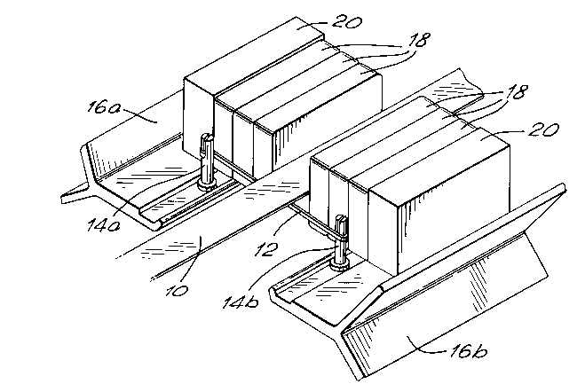
Fig. 1 is an isometric view of a first embodiment
10 of mounting arrangement; and
Fig. 2 is a schematic diagram of a second mounting
arrangement.
Referring to the drawings, there is shown in Fig. 1
a ribbon foil 10 which constitutes part of a ribbon
15 transducer, for example for a loudspeaker. Beneath the
underside of the ribbon foil 10 lies a cross-suspension
element 12. This is in the form of a band or strip
which is affixed, for example by adhesive, to the
underside of the ribbon foil. The ends of the cross-
20 suspension element 12 are secured in suspension pillars14a and 14b positioned one on each side of the ribbon
foil so that the element 12 lies at right-angles to the
longitudinal axis of the foil. Each of the suspension
pillars 14a, 14b is provided with a slot in the end
25 thereof, so that the pillars can be rotated, for
example with a screwdriver. The suspension pillars
14a, 14b are mounted on rear and front extrusion plates
16a and 16b respectively so that they can be rotated
relative to the support plates and will hold their
30 adjusted positions. The front and rear extrusion
plates 16a, 16b also serve as support plates for
magnets 18 which are held in place by backing plates
20.
In use, in order to centre the ribbon foil 10, it
35 is simply necessary to displace the cross-suspension

2019S40
element 12 by rotation of the suspension pillars until
the ribbon foil is accurately centered. A maximum
displacement of plus or minus 1 millimetre is generally
sufficient.
It will be appreciated that the ribbon foil 10 is
provided with a plurality of cross-suspension elements
12 at intervals along its length so that the foil can
be accurately centered throughout its length.
Alternative methods of mounting the cross-
10 suspension elements 12 may be devised within the scope
of the present invention. For example, as shown in
Fig. 2, instead of providing a suspension pillar on
each side of the ribbon foil, the cross-suspension
element 12 could be mounted between the two limbs 22,
15 23 of a generally U-shaped support member 24, for
example a plastics moulding. Adjustment means would
then be provided for moving the cross-suspension
element 12 relative to the U-shaped support 24.
Alternatively, the U-shaped support 24 could be movable
20 bodily, with the cross-suspension element 12, to effect
the re~uired adjustment. Various other alternative
methods of mounting and support will be apparent to
those skilled in the art.

Dessin représentatif
Une figure unique qui représente un dessin illustrant l'invention.
États administratifs

2024-08-01 : Dans le cadre de la transition vers les Brevets de nouvelle génération (BNG), la base de données sur les brevets canadiens (BDBC) contient désormais un Historique d'événement plus détaillé, qui reproduit le Journal des événements de notre nouvelle solution interne.

Veuillez noter que les événements débutant par « Inactive : » se réfèrent à des événements qui ne sont plus utilisés dans notre nouvelle solution interne.

Pour une meilleure compréhension de l'état de la demande ou brevet qui figure sur cette page, la rubrique Mise en garde , et les descriptions de Brevet , Historique d'événement , Taxes périodiques et Historique des paiements devraient être consultées.

Historique d'événement

Description Date
Inactive : CIB de MCD 2006-03-11
Le délai pour l'annulation est expiré 1998-06-22
Lettre envoyée 1997-06-23
Accordé par délivrance 1995-07-18
Exigences pour une requête d'examen - jugée conforme 1993-10-14
Toutes les exigences pour l'examen - jugée conforme 1993-10-14
Demande publiée (accessible au public) 1990-12-21

Historique d'abandonnement

Il n'y a pas d'historique d'abandonnement

Titulaires au dossier

Les titulaires actuels et antérieures au dossier sont affichés en ordre alphabétique.

Titulaires actuels au dossier
CELESTION INTERNATIONAL LIMITED
Titulaires antérieures au dossier
GRAHAM BANK
HAROLD C. PINFOLD
Les propriétaires antérieurs qui ne figurent pas dans la liste des « Propriétaires au dossier » apparaîtront dans d'autres documents au dossier.
Documents

Pour visionner les fichiers sélectionnés, entrer le code reCAPTCHA :


Pour visualiser une image, cliquer sur un lien dans la colonne description du document. Pour télécharger l'image (les images), cliquer l'une ou plusieurs cases à cocher dans la première colonne et ensuite cliquer sur le bouton "Télécharger sélection en format PDF (archive Zip)" ou le bouton "Télécharger sélection (en un fichier PDF fusionné)".

Liste des documents de brevet publiés et non publiés sur la BDBC .

Si vous avez des difficultés à accéder au contenu, veuillez communiquer avec le Centre de services à la clientèle au 1-866-997-1936, ou envoyer un courriel au Centre de service à la clientèle de l'OPIC.


Description du
Document 
Date
(aaaa-mm-jj) 
Nombre de pages   Taille de l'image (Ko) 
Page couverture 1995-07-18 1 16
Abrégé 1995-07-18 1 12
Description 1995-07-18 3 117
Revendications 1995-07-18 1 40
Dessins 1995-07-18 1 28
Dessin représentatif 1999-07-27 1 27
Avis concernant la taxe de maintien 1997-09-15 1 179
Taxes 1996-07-22 1 48
Correspondance 1995-08-23 1 18
Taxes 1995-06-29 2 109
Taxes 1994-05-27 1 34
Taxes 1992-05-27 1 27
Taxes 1993-06-08 1 26
Courtoisie - Lettre du bureau 1994-12-09 1 20
Correspondance de la poursuite 1993-10-14 3 91
Demande de l'examinateur 1993-11-23 2 75
Correspondance de la poursuite 1994-02-22 2 52
Correspondance reliée au PCT 1994-08-09 4 130
Correspondance reliée au PCT 1995-05-10 1 35
Courtoisie - Lettre du bureau 1994-10-17 1 19
Correspondance reliée au PCT 1994-11-09 6 190
Courtoisie - Lettre du bureau 1994-05-09 1 18
Courtoisie - Lettre du bureau 1993-11-02 1 57
Courtoisie - Lettre du bureau 1991-11-15 1 19
Courtoisie - Lettre du bureau 1990-09-14 1 43