Sélection de la langue

Search

Sommaire du brevet 2019590 

Énoncé de désistement de responsabilité concernant l'information provenant de tiers

Une partie des informations de ce site Web a été fournie par des sources externes. Le gouvernement du Canada n'assume aucune responsabilité concernant la précision, l'actualité ou la fiabilité des informations fournies par les sources externes. Les utilisateurs qui désirent employer cette information devraient consulter directement la source des informations. Le contenu fourni par les sources externes n'est pas assujetti aux exigences sur les langues officielles, la protection des renseignements personnels et l'accessibilité.

Disponibilité de l'Abrégé et des Revendications

L'apparition de différences dans le texte et l'image des Revendications et de l'Abrégé dépend du moment auquel le document est publié. Les textes des Revendications et de l'Abrégé sont affichés :

  • lorsque la demande peut être examinée par le public;
  • lorsque le brevet est émis (délivrance).
(12) Brevet: (11) CA 2019590
(54) Titre français: CHAUFFAGE A REGULATION AUTOMATIQUE, POUR EMPECHER LE GEL D'UNE CANALISATION D'EAU
(54) Titre anglais: SELF-REGULATING FREEZE-PROOF WATER PROTECTION SYSTEM
Statut: Durée expirée - au-delà du délai suivant l'octroi
Données bibliographiques
Abrégés

Abrégé anglais


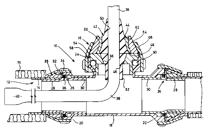
A heating system for a fluid duct such as a
water supply pipe utilizes a self-limiting heater cable
located within the duct and an insulation around the
duct. The cable is inserted through a T-fitting having a
scaling member with oppositely directed conical surfaces
to engage the fitting and seal against the cable.

Revendications

Note : Les revendications sont présentées dans la langue officielle dans laquelle elles ont été soumises.


CLAIMS
1. A domestic water system comprising a pipe having a
peripheral wall for conveying water between a source and a
distribution system, thermal insulating means encompassing the
outer surface of said pipe to inhibit heat loss therefrom, an
elongate heating cable extending within and along said pipe
and coupling means to permit passage of said heating cable
across the wall of said pipe, said heating cable comprising a
self-limiting heater cable having a heating effect inversely
proportional to the temperature of fluid in said pipe and
being connectable at one end to a power source external of
said duct and sealed at its opposite end to prevent ingress of
said fluid.
2. A domestic water system according to claim 1 wherein
said coupling means permits egress of said heating means
normal to the longitudinal axis of said pipe.
3. A domestic water supply system according to claim 2
wherein said coupling means are incorporated in a T-fitting in
said duct.
4. A domestic water supply system according to claim 3
wherein said coupling means includes a pair of opposed conical
surfaces and a sealing member disposed therebetween, said
cable passing through said member.
5. A domestic water supply system according to claim 4
wherein opposed conical surfaces on said sealing members are
interconnected by a planar shoulder.
6. A domestic water supply system according to claim 5
wherein said shoulder abuts against a planar surface adjacent
one of said conical surfaces.
7. A domestic water supply system according to claim 6
wherein said surface and said one conical surface is formed on
an annular plug received within one limb of said T-fitting.
8. A domestic water supply system according to claim 7
wherein said annular plug is received within a cylindrical
bore and sealed by an O-ring.
9. A domestic water supply system according to claim 6
wherein the other of said conical surfaces is formed on one of
a pair of nested collars rotatable relative to one another,

said collars being retained by rotatable fastening means
engageable with the other of the collars to force the one
collar into engagement with said sealing member, relative
rotation between the collars inhibiting torque transmission to
said sealing member upon rotation of said fastening means.
10. A domestic water supply system according to claim 1
wherein said pipe is formed from a plastics material.
11. A kit for installation in a water supply pipe to inhibit
freezing of water therein, said kit comprising a heater cable
to be inserted within and extend along the pipe, a fitting to
connect said pipe to a distribution system and having a cable
port to allow passage of the able from the exterior to the
interior of the pipe, said cable port being disposed to allow
egress of said cable normal to the pipe and sealing means to
seal the cable in the port and prevent fluid passing
therethrough.
12. A kit according to claim 11 wherein said fitting is
a T-piece having a pair of aligned ports for connection
between a pipe and a distribution system and said port being
disposed normal thereto.
13. A kit according to claim 12 further including an
insulating material for application to the exterior of said
pipe .
14. A kit according to claim 13 including a control to
regulate the heating effect of the cable.
15. A kit according to any one of claims 11, 12 or 13
wherein said heater cable is self regulating to have a heating
effect inversely proportional to the temperature of fluid in
the pipe.
16. A kit according to claim 12 wherein said coupling
means includes a pair of opposed conical surfaces and a
sealing member disposed therebetween, said cable passing
through said member.
17. A kit according to claim 16 wherein opposed conical
surfaces on said sealing members are interconnected by a
planar shoulder.

18. A kit according to claim 17 wherein said shoulder
abuts against a planar surface adjacent one of said conical
surfaces.
19. A kit according to claim 18 wherein said surface and
said one conical surface is formed on an annular plug received
within one limb of said T-fitting.
20. A kit according to claim 19 wherein said annular
plug is received within a cylindrical bore and sealed by an O-
ring.
21. A kit according to claim 18 wherein the other of
said conical surfaces is formed on one of a pair of nested
collars rotatable relative to one another, said collars being
retained by rotatable fastening means engageable with the
other of the collars to force the one collar into engagement
with said sealing member, relative rotation between the
collars inhibiting torque transmission to said sealing member
upon rotation of said fastening means.
22. A kit according to any one of claims 16, 17 or 18
wherein said heater cable is self regulating to have a heating
effect inversely proportion to the temperature of fluid in
said pipe.
23. A kit according to any one of claims 19, 20 or 21
wherein said heater cable is self regulating to have a heating
effect inversely proportion to the temperature of fluid in
said pipe.

Description

Note : Les descriptions sont présentées dans la langue officielle dans laquelle elles ont été soumises.


2019~gO
The present invention relates to a fluid supply
system and in particular although not exclusively to such
a system for use in inclement environments.
It is of course well known that fluids such as
water may be delivered between spaced locations by using
an enclosed duct such as a plastics pipe with the fluid
being pumped along the pipe. In certain installations,
the pipe may be exposed to sufficiently low temperatures
that the fluid in the pipe may freeze and cause extensive
damage to the fluid supply system. One solution to this
problem is to ensure that the pipe is buried at a depth
where the freezing temperatures are not encountered.
This of course is the normal manner in which water is
supplied to a house.
In certain environments, however, it is not
possible to bury the pipe due to the nature of the
ground, and so alternative solutions have to be found.
Attempts to insulate the pipe are unsuccessful because
the supply may be used intermittently and there is no
residual heat to maintain the fluid above freezing
temperature.
One system that has been utilized is a heating
cable installed within the pipe. However, these have not
been particularly successful as the heating cables do not
permit insulation of the pipe. The heating effect is
constant and may therefore cause boiling of the fluid
within the pipe. To ensure a constant heat loss, the
pipe must remain uninsulated which also means that the
previous systems are very expensive to run. Moreover,
pervious systems require the heater to be activated if
there is any possibility of the temperature falling below
the freezing point which means that the time over which
they must be used is extensive.
It is an object of the present invention to
provide a fluid supply system in which the above
disadvantages are obviated or mitigated.
According to the present invention, there is
provided a fluid supply system comprising an enclosed

20~5~0
duct having a peripheral wall for conveying fluid between
a pair of spaced locations, thermal insulating means
encompassing the outer surface of said duct, heating
means extending along said duct and coupling means to
permit passage of said heating means across the wall of
said duct, said heating means comprising a self-limiting
heater cable for connection at one end to a power source
external of said duct and sealed at its opposite end to
prevent ingress of said fluid.
By utilizing a self-regulating heating cable
which reduces the heating effect as the temperature
increases, the power consumption is reduced and the pipe
may be insulated to improve the efficiency of the system
further.
In a preferred embodiment, the heater cable
enters the duct along an axis normal to the longitudinal
axis of the duct which then ensures that fluid flow
through the duct is not unduly disturbed.
As a further preference, the coupling through
which the cable may enter the duct includes a pair of
opposed conical surfaces with a complimentary sealing
member disposed between them. The cable passes through
the sealing member.
It is also preferred that the sealing member
has a planar shoulder abutting a planar surface in the
coupling to ensure an effective seal about the cable.
An embodiment of the invention will now be
described by way of example only with reference to the
accompanying drawings in which
figure 1 is a sectional view through a portion
of a water supply system; and
figure 2 is an exploded view similar to figure
1 showing the components of the fluid supply system.
Referring the drawings, a water supply system
10 includes an enclosed duct 12, preferably a plastics
pipe, to convey water from a source not shown to a pump
not shown. Duct 12 includes a continuous peripheral wall

2~sssa
14 and has a coupling 16 located between two runs of the
duct 12.
The coupling 16 includes a T-fitting 18 having
a pair of aligned threaded bosses 20,22 and a third boss
24 disposed at 90o to the longitudinal axis of the duct
12. Bosses 20,22 receive sleeves 26 each of which has a
nipple 28 at one end for insertion into the duct 12 and
an annular boss 30 at the opposite end for insertion
within the T-fitting 18. A flange 32 extends radially
beyond the boss 30 and is secured to the T-fitting by
means of a compression ring 33 and a threaded collar 34
which co-operates with the respective one of the threaded
bosses 22,24. An O-ring 36 is used to seal between the
boss 30 and the interior of the T-fitting 18 to ensure
watertight connection.
The boss 24 disposed at right angles to the
bosses 22 and 24 is provided to permit entry of a heater
cable 38 into the interior of the duct 12 without causing
a change in teh direction of the flow of water along duct
12. Heater cable 38 is a self-limiting cable such as
that available from the Raychem Corporation under serial
number 3BTV1-CT. Cable 38 is arranged with a pair of
parallel conductors interconnected by heating elements
and operates to reduce the heating effect as the ambient
temperature increases. The distil end of cable 38 is
sealed as indicated at 40 to prevent ingress of fluid
into the cable. The cable comprises a pair of space
conductors with a semi-conductive core extending between
them.
Cable 38 is sealed within the T-fitting 18 by a
sealing member 42 having a pair of oppositely directed
conical surfaces 44,46 that are interconnected by means
of a planar shoulder 48. Seal member 42 has a bore 50
extending through it to accomodate the cable 38 and the
lower conical surface 46 terminates in a cylindrical plug
52.

2019~9~
The sealing member 42 is received within a
collar 54 that has a conical surface 56. The collar 54
has a circumferential flange 58 that abuts against the
upper surface of the boss 24 with an 0-ring 60 to seal
between the collar and the boss.
The opposite conical surface 44 of seal member
42 is received within the innermost of a pair of nested
rings 62,64. The rings are retained within one another
by means of a detente indicated at 66 and may rotate
relative to one another and thereby avoid transmitting
torque between the two rings.
The rings 62,64 are retained on the boss 24 by
means of the threaded collar 68 engaging with the threads
of the boss 24.
The duct 12 to either side of fitting 16 is
encompassed by an insulating layer 70 of appropriate
thickness to minimize heat transfer. It will also be
appreciated that the heater cable 38 may be connected to
a suitable source of electrical power by means of a
conventional electrical outlet or the like which has not
been shown.
In operation, the fitting 16 is assembled in
the duct 12 and the cable inserted through the seal
member 42 and collar 54. The nested rings 62,64 are then
slid over the cable and onto the outer surface of the
seal member 42. The collar 68 is then threaded onto the
boss and tightened to compress the seal member 42. The
disposition of the rings 62,64 ensures that the torque
induced by the threaded collar 68 is not transmitted into
the seal member 42 and so does not twist the seal member
within the fitting. Moreover, the shoulder 48 provided
between the opposed conical surfaces 44,46 provides a
positive abutment against the upper surface of collar 54
that ensures correct compression of the conical portion
44 by the rings 60,62 and ensures a proper seal against
the cable 38.

~Ol9~gO
Once the cable is inserted, it is connected to
a suitable power source and then operates to generate
heat within the duct 12. This heat is of course
transferred to fluid in the duct 12 and prevents freezing
of that fluid. Because the cable 38 is self-limiting,
its heating effect diminishes as the temperature about it
increases. Thus, there is no danger of fluid in the duct
12 boiling or any danger of the cable being damaged in
the event that there is no fluid in the duct due to it
having drained.
Because of the self-limiting nature of the
cable 38, it is possible to insulate the duct as shown by
the insulation 70 and thus lower operating costs and also
provide protection against marginal conditions in which
the heating cable is not activated.
It will b e noted that the cable is inserted
through the T-fitting and so does not cause a diversion
of the flow of fluid through the duct 12 at the fitting.
This is of significant importance in the installation as
any undue changes in direction can impede the performance
of the pump connected to the fitting.

Dessin représentatif
Une figure unique qui représente un dessin illustrant l'invention.
États administratifs

2024-08-01 : Dans le cadre de la transition vers les Brevets de nouvelle génération (BNG), la base de données sur les brevets canadiens (BDBC) contient désormais un Historique d'événement plus détaillé, qui reproduit le Journal des événements de notre nouvelle solution interne.

Veuillez noter que les événements débutant par « Inactive : » se réfèrent à des événements qui ne sont plus utilisés dans notre nouvelle solution interne.

Pour une meilleure compréhension de l'état de la demande ou brevet qui figure sur cette page, la rubrique Mise en garde , et les descriptions de Brevet , Historique d'événement , Taxes périodiques et Historique des paiements devraient être consultées.

Historique d'événement

Description Date
Inactive : Périmé (brevet - nouvelle loi) 2010-06-25
Inactive : CIB de MCD 2006-03-11
Inactive : Grandeur de l'entité changée 2005-07-13
Lettre envoyée 1999-07-16
Accordé par délivrance 1994-12-06
Exigences pour une requête d'examen - jugée conforme 1994-04-08
Toutes les exigences pour l'examen - jugée conforme 1994-04-08
Demande publiée (accessible au public) 1991-12-25

Historique d'abandonnement

Il n'y a pas d'historique d'abandonnement

Historique des taxes

Type de taxes Anniversaire Échéance Date payée
TM (brevet, 8e anniv.) - petite 1998-06-25 1998-05-19
TM (brevet, 10e anniv.) - petite 2000-06-27 1999-06-25
TM (brevet, 9e anniv.) - petite 1999-06-25 1999-06-25
TM (brevet, 11e anniv.) - petite 2001-06-25 2001-05-17
TM (brevet, 12e anniv.) - petite 2002-06-25 2002-04-16
TM (brevet, 13e anniv.) - petite 2003-06-25 2003-06-25
TM (brevet, 14e anniv.) - petite 2004-06-25 2004-06-01
TM (brevet, 15e anniv.) - générale 2005-06-27 2005-06-27
TM (brevet, 16e anniv.) - générale 2006-06-26 2006-04-12
TM (brevet, 17e anniv.) - générale 2007-06-25 2007-04-10
TM (brevet, 18e anniv.) - générale 2008-06-25 2008-05-29
TM (brevet, 19e anniv.) - générale 2009-06-25 2009-05-13
Titulaires au dossier

Les titulaires actuels et antérieures au dossier sont affichés en ordre alphabétique.

Titulaires actuels au dossier
HEAT-LINE CORPORATION
Titulaires antérieures au dossier
LORNE HEISE
Les propriétaires antérieurs qui ne figurent pas dans la liste des « Propriétaires au dossier » apparaîtront dans d'autres documents au dossier.
Documents

Pour visionner les fichiers sélectionnés, entrer le code reCAPTCHA :


Pour visualiser une image, cliquer sur un lien dans la colonne description du document. Pour télécharger l'image (les images), cliquer l'une ou plusieurs cases à cocher dans la première colonne et ensuite cliquer sur le bouton "Télécharger sélection en format PDF (archive Zip)" ou le bouton "Télécharger sélection (en un fichier PDF fusionné)".

Liste des documents de brevet publiés et non publiés sur la BDBC .

Si vous avez des difficultés à accéder au contenu, veuillez communiquer avec le Centre de services à la clientèle au 1-866-997-1936, ou envoyer un courriel au Centre de service à la clientèle de l'OPIC.


Description du
Document 
Date
(aaaa-mm-jj) 
Nombre de pages   Taille de l'image (Ko) 
Abrégé 1994-12-05 1 10
Description 1994-12-05 5 215
Abrégé 1994-12-05 1 10
Revendications 1994-12-05 3 130
Dessins 1994-12-05 2 42
Dessin représentatif 1998-07-21 1 22
Taxes 2003-06-24 1 24
Correspondance 1999-07-15 2 46
Taxes 2000-06-26 1 33
Taxes 2004-05-31 2 71
Taxes 2005-06-26 1 29
Taxes 2006-04-11 1 34
Taxes 2007-04-09 1 32
Taxes 2008-05-28 1 26
Taxes 1997-05-19 1 76
Taxes 1996-06-23 1 61
Taxes 1995-07-27 1 53
Taxes 1995-07-25 1 27
Taxes 1995-07-18 1 24
Taxes 1995-07-18 1 42
Taxes 1994-06-02 1 44
Taxes 1995-05-30 1 30
Taxes 1992-06-24 1 28
Correspondance de la poursuite 1994-03-15 6 260
Correspondance reliée au PCT 1994-03-15 1 31
Courtoisie - Lettre du bureau 1994-04-20 1 33
Correspondance de la poursuite 1994-04-10 2 75
Courtoisie - Lettre du bureau 1992-04-14 1 10
Courtoisie - Lettre du bureau 1990-09-13 1 34