Sélection de la langue

Search

Sommaire du brevet 2020300 

Énoncé de désistement de responsabilité concernant l'information provenant de tiers

Une partie des informations de ce site Web a été fournie par des sources externes. Le gouvernement du Canada n'assume aucune responsabilité concernant la précision, l'actualité ou la fiabilité des informations fournies par les sources externes. Les utilisateurs qui désirent employer cette information devraient consulter directement la source des informations. Le contenu fourni par les sources externes n'est pas assujetti aux exigences sur les langues officielles, la protection des renseignements personnels et l'accessibilité.

Disponibilité de l'Abrégé et des Revendications

L'apparition de différences dans le texte et l'image des Revendications et de l'Abrégé dépend du moment auquel le document est publié. Les textes des Revendications et de l'Abrégé sont affichés :

  • lorsque la demande peut être examinée par le public;
  • lorsque le brevet est émis (délivrance).
(12) Brevet: (11) CA 2020300
(54) Titre français: FIXATION POUR MUR EPAIS
(54) Titre anglais: THICK WALL STABILIZING CLIP
Statut: Durée expirée - au-delà du délai suivant l'octroi
Données bibliographiques
(51) Classification internationale des brevets (CIB):
  • E04B 1/41 (2006.01)
(72) Inventeurs :
  • CIRCELLI, MICHAEL J. (Canada)
  • CIRCELLI, WILLIAM F. (Canada)
  • CARROZZA, TONY (Canada)
(73) Titulaires :
  • PAMCOE PRODUCTS INTERNATIONAL INC.
(71) Demandeurs :
  • PAMCOE PRODUCTS INTERNATIONAL INC. (Canada)
(74) Agent: SMART & BIGGAR LP
(74) Co-agent:
(45) Délivré: 1995-09-26
(22) Date de dépôt: 1990-07-03
(41) Mise à la disponibilité du public: 1991-09-16
Requête d'examen: 1991-12-23
Licence disponible: S.O.
Cédé au domaine public: S.O.
(25) Langue des documents déposés: Anglais

Traité de coopération en matière de brevets (PCT): Non

(30) Données de priorité de la demande:
Numéro de la demande Pays / territoire Date
07/493,667 (Etats-Unis d'Amérique) 1990-03-15

Abrégés

Abrégé anglais


A clip is provided having a base of generally
planar configuration with a free end and first and second
flanges integral with and extending away from the base for
bearing on opposite surfaces of a thick wall. The second
flange is intermediate the first flange and the free end of
the base. A method is provided for making such a clip in
which a metal blank of desired length and width is bent
generally at right angles to form the first flange. The
blank is slit to define an aperture having three sides and
a tongue. The tongue is bent to form the second flange.
A method is provided for providing lateral support to a
thick wall in which such a clip which is laid over a top
edge of the wall and secured to a supporting surface.

Revendications

Note : Les revendications sont présentées dans la langue officielle dans laquelle elles ont été soumises.


- 10 -
THE EMBODIMENTS OF THE INVENTION IN WHICH AN EXCLUSIVE PROPERTY
OR PRIVILEGE IS CLAIMED ARE DEFINED AS FOLLOWS:
1. A clip for stabilizing a thick wall comprising:
a base of generally planar configuration having a free
end;
first and second flanges integral with and extending
from said base for bearing on opposite surfaces of said wall;
said first flange extending from the opposite end of
said base from said free end; and
said second flange being intermediate said first flange
and said free end of said base; and
an aperture extending away from said second flange
toward said first flange, said aperture having a width at least
equal to the width of said second flange and a length at least
equal to the thickness of said second flange to enable a
plurality of said clips to be stacked with the second flange of
one clip extending through the aperture of the adjacent clip with
said first and second flanges of said one clip being displaced
toward the same side of the corresponding first and second
flanges of said adjacent clip.
2. A clip for stabilizing a thick wall comprising:
a base of generally planar configuration having a free
end;
first and second flanges integral with and extending
from said base for bearing on opposite surfaces of said wall;
said first flange extending from the opposite end of
said base from said free end;
said second flange being intermediate said first flange
and said free end of said base;
said second flange having been formed by bending from
a slit portion of said base;
said slit portion defining, after bending, an aperture
in said base having a width greater than the width of said second
flange and extending toward said first flange to enable a

- 11 -
plurality of said clips to be stacked with the second flange of
one clip extending through the aperture of the adjacent clip with
said first and second flanges of said one clip being displaced
to the same side of the corresponding first and second flanges
of the adjacent clip.
3. A clip as claimed in claims 1 or 2 wherein said second
flange has a width of from 25% to 75% of the width of said first
flange.
4. A clip as claimed in claims 1 or 2 wherein said base
further has at least one mounting hole extending therethrough
intermediate said second flange and said free end.
5. A clip as claimed in claim 3 wherein said base further
has at least one mounting hole extending therethrough
intermediate said second flange and said free end.
6. A method of providing lateral support to a thick wall
comprising the steps of:
(i) laying over a top edge of said wall a clip, said
clip having a base of generally planar configuration and
including a free end; first and second flanges integral with and
extending from said base for bearing on opposite surfaces of said
wall; said second flange being intermediate said first flange and
said free end of said base; said clip further having an aperture
in said base extending away from said second flange toward said
first flange and having a width at least equal to the width of
said second flange and a length equal to the thickness of said
second flange; and,
(ii) securing said base to a supporting surface.
7. A method of providing lateral support to a thick wall
comprising the steps of:
(i) laying over a top edge of said wall a clip, said
clip having a base of generally planar configuration and

- 12 -
including a free end; first and second flanges integral with and
extending from said base for bearing on opposite surfaces of said
wall; said second flange being intermediate said first flange and
said free end of said base; said second flange having been formed
by bending from a slit portion of said base; said slit portion
defining, after bending, an aperture in said base having a width
greater than the width of said second flange; and,
(ii) securing said base to a supporting surface.
8. A method of making a clip for supporting a thick wall
comprising the steps of:
(i) forming a metal blank of desired length and width;
(ii) bending said blank to form a first flange at one
end of said blank;
(iii) slitting said blank to define an aperture in
said blank having three sides and a tongue in said aperture, the
width of said aperture being greater than the width of said
tongue; and said aperture extending from said tongue toward said
first flange;
(iv) bending said tongue to form a second flange
generally parallel to said first flange and spaced from said
first flange an amount generally equal to the thickness of said
wall.

Description

Note : Les descriptions sont présentées dans la langue officielle dans laquelle elles ont été soumises.


2~2~ao
FIELD OF TH~ lNV~.. rION
This invention qenerally relates to support
brackets used in the construction industry and more
particularly relates to a lateral ~upport clip for
stabilizing a thick wall.
RAr~ouND OF ~ INV~N 110N
In this patent specification, the term "thick
wall~ is used to refer to a wall which has some structural
rigidity, such as a block wall, as distinguished from a
10 Npartition-type n wall such as one of drywall construction.
A thick wall typically has a thicknes~ of 3 1/2 or more
inches. It is to be understood that the term ~thick wall"
is intended to include similar section~ such as a window
mullion.
In the construction industry, when a thick wall
is being erected between a floor and a ceiling, it is
necessary to provide lateral support at the top of the
wall. Such lateral support may be provided by securing the
top edge of the wall to an adjacent ceiling or structural
member. Various brackets or clips have been devised for
achieving such a connection.
One of the prior devices comprises a generally F
shaped clip which is placed over the upper course of blocks
with each arm of the F on opposite sides of the block and
the tail projecting away from one of the sides. Once the
block has been laid, a suitable fastener is then used to

20203~0
- 3 -
attach the tail of the clip to the surface which is to
provide lateral support. The attachment means selected
depends on the nature of the supporting surface. Common
attachment means include bolting, screwing, welding and
S explosive-charge driven fasteners.
Prior F shaped clips of the type described above
have been manufactured from two pieces of ~heet metal or
metal plate. One of the piece~ i8 bent at right angles to
define the back of the F and the upper arm. The other
piece is then welded at right angles to the back of the F
to form the other arm. Disadvantages with such cl ip8
include high manufacturing costs, heat distortion during
welding and handling difficulties. The manufacturing costs
result from the complexity of the manufacturing process
which includes ~oining two components by means of welding.
The handling difficulties stem from the shape of the clips
preventing stacking in such a manner as to minimize the
space taken by the clips.
It will be appreciated that handling difficulties
are exacerbated as the overall size of the clip increases.
While a number of relatively small clips may readily be
packaged in a box or the like, larger clips require
considerably more space and packaging becomes quite a
problem. The prior art clips occupy a fair volume and
require a relatively large container to store a relatively
small number of clips. As typical construction codes
require that such clips be spaced at rather frequent

2020300
-- 4
intervals along a wall, the volume of space occupied by the
packaged clips is quite significant and reflects on
handling, storage and shipping costs.
SUMMARY 0~ THÆ INVENTION
A clip is provided for stabilizing a thick wall,
the clip comprises:
a base of generally planar configuration having
a free end;
fir~t and second flanges integral with and
extending from said base for bearing on opposite surfaces
of said wall;
said second flange being intermediate said first
flange and said free end of said base; and,
an aperture extending away from said second
flange toward said first flange, said aperture having a
width at least equal to the width of said f~rst flange and
a length at least equal to the thickness of said second
flange.
A method is provided for providing lateral
support to a thick wall compri~ing:
laying over a top edge of said wall a clip as set
out above and securing said base of said clip to a
supporting surface.
A method is also provided for making a clip for
supporting a thick wall comprising the steps of:

20~0300
-- 5 --
forming a metal blank of desired length and
width;
bending said blank to form a first flange at one
end of said blank;
slitting said blank to define an aperture in said
blank having three sides and a tongue in said aperture, the
width of said aperture being greater than the width of said
tongue;
bending said tongue to form a second flange
generally parallel to said first flange and spaced from
said first flange an amount generally equal to the
thickness of said wall.
BRIEF DESCRIPTION OF THE DRAWINGS
The invention will now be described with
reference to the attached drawings in whichs
Fig. 1 is a side sectional view showing a clip
according to the present invention in use;
Fig. 2 is an isometric view of a prior art clip;
Fig. 3 is an isometric view of a clip according
to the present invention;
Fig. 4 is a top plan view of a blank for making
a clip according to the present invention;
Fig. 5 is a side view showing the stacking of
clips according to the present invention; and
And, Fig. 6 shows an alternate embodiment of a
clip according to the present invention.

2~203ao
-- 6 --
D13SCRIPTION OP' PR~FERRED EMBODIllENTS OF l~IE PRESENT
IN V~I. . ION
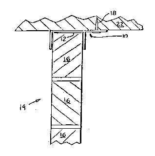
Fig. 1 shows a clip, indicated generally by
reference lO, having a generally F shaped profile
S surmounting the top edge 12 of a wall 14 comprised of
blocks 16. Securing meanq, such as a fastener 18, secure
the clip lO to a securing surface, namely the underside 20
of a concrete slab 22.
Fig. 2 shows a prior art clip having first and
second arms, 30 and 32 respectively, extending generally at
right angles from a back 34. The second arm 32 extends
across the full width of the back 34 and is attached
thereto by a stitch weld running therebetween at 36.
Fig. 3 shows a clip 50 according to the present
invention. The clip 50 has a generally plansr rectangular
base 52 having a free end 54. First and second flange~, 56
and 58 respectively, are integral with the base 52 and
extend generally at right angles thereto. The second
flange 58 is intermediate the first flange 56 and the free
end 54 of the base 52. The base 52 has a generally
rectangular aperture 60 extending away from the second
flange 58. The aperture 60 has a width greater than the
width of the second flange 58. Although in most cases the
flanges would be perpendicular to the base, it will be
appreciated that this is not a necessary requirement. In
a different arrangement the flange may be bent to other

202~300
-
-- 7 --
than a perpendicular angle relative to the base with both
flanges nonetheless being generally parallel to each other.
Fig. 4 shows a blank 70 from which a clip such as
the clip 50 in Figure 3 may be formed. The blank 70 may be
formed from metal using conventional metal forming
techniques such as cutting or stamping to the desired
length and width. The blank is bent generally at right
angles along the dashed line 72 to form a first flange such
as 56 in Fig. 3. The blank i8 slit at 74 to form a
generally C-shaped aperture having a tongue 76 therein.
The tongue 76 is bent along the dashed line 78 to form a
second flange such as 58 in Fig. 3. The first and second
flan~es, 56 and 58 respectively, are formed 80 as to be
generally parallel to each other and spaced by an amount
generally equal to the thickness of the wall to be
supported by the clip 50.
It will be appreciated that as the cl$p 50 has an
aperture 60 wider than the second flange 58, it is possible
to stack a series of clips 50 one above the other as
illustrated in Fig. 5. Clip 50a having a first flange
58a, a second flange 56a and an aperture 60a, is shown
placed on a second clip 50b having a second flange 58b
extending through the aperture 60a in the first clip 50a.
References 60b and 56b respectively denote the aperture and
first flange of the second clip 50b.
Figure 6 shows an alternate embodiment of a clip
according to the present invention wherein both the first

2Q20~00
-- 8 --
flange 56a and the second flange 58a have been formed by
bending from a slit portion of the base 50. Such slitting
and bending to form the first flange 56a results in a first
aperture 60a extending from the first flange 56a toward the
second flange 58 and a second aperture 60b extending from
the second flange 58 toward the free énd 54a of the base
50a. As such a clip would have a tab 78 extending from the
base away from the first flange 56a and the first aperture
60a, it would typically be used for partition type walls or
the like rather than outside walls and may be secured on
both sides of such a wall.
In stacking the clip of Fig. 6, the first and
second flanges, 56a and 58a of an overlying clip would be
respectively received within the first and second apertures
60a and 60b of an underlying clip. To maximize
stackability of a clip according to this alternate
embodiment, the length of the apertures should correspond
to the length of the flanges.
The clip may be provided with a mounting hole
such as indicated at reference 62 through which a fastener
may be inserted. Such a hole i8 not neceqsary when using
an explosive rharge driven fastener.
Suitable results have been obtained using clips
manufactured from 12 or 14 gauge galvanized metal secured
using two Hilti ttrade mark) or similar fasteners. To
ensure that the first and second flanges, 56 and 58, have
generally the same strength, the width of the second

20~0300
~.,
g
flange should be approximately the same a~ the total width
of the two strips of material on either Qide of the
aperture 60. Various widths however may be used.
Typically the width of the second flange 58 would vary from
5 25 to 75% of the width of the first flange 56. Suitable
results have been obtained u~ing clips having a flange
length of from 2" to 2 1/2 n Preferably the distance
between the first and second flanges, 56 and 58
respectively, should be approximately 1/8" greater than the
10 thickness of the wall to be supported Accordingly, this
distance might be 3 5/8, 5 5/8", 7 5/8 n 9 5/8' or 11 5/8
for 3 1/2 n ~ 5 1/2", 7 1/2"or 11 1/2 blocks respectively.
Variations to the clip de~cribed above may be
apparent to persons skilled in the art of forming such
15 clips without departing from the ~pirit and scope of the
present invention. Such variations may arise in adapting
the clip to particular walls or adapting the manufacturing
technique to specific material~. For example, if
galvanized metal is used the radius of the bends should be
20 great enough to ensure that the galvanized finish is not
cracked ad~acent the bend. Furthermore, materials other
than metal might be used for the clip in appropriate
circumstances, for example plastic might be used with
suitable modifications being made to the manufacturing
25 process such as extrusion rather than bending.

Dessin représentatif
Une figure unique qui représente un dessin illustrant l'invention.
États administratifs

2024-08-01 : Dans le cadre de la transition vers les Brevets de nouvelle génération (BNG), la base de données sur les brevets canadiens (BDBC) contient désormais un Historique d'événement plus détaillé, qui reproduit le Journal des événements de notre nouvelle solution interne.

Veuillez noter que les événements débutant par « Inactive : » se réfèrent à des événements qui ne sont plus utilisés dans notre nouvelle solution interne.

Pour une meilleure compréhension de l'état de la demande ou brevet qui figure sur cette page, la rubrique Mise en garde , et les descriptions de Brevet , Historique d'événement , Taxes périodiques et Historique des paiements devraient être consultées.

Historique d'événement

Description Date
Inactive : Périmé (brevet - nouvelle loi) 2010-07-03
Inactive : Lettre officielle 2006-07-24
Inactive : Grandeur de l'entité changée 2006-07-13
Inactive : Paiement correctif - art.78.6 Loi 2006-06-29
Accordé par délivrance 1995-09-26
Exigences pour une requête d'examen - jugée conforme 1991-12-23
Toutes les exigences pour l'examen - jugée conforme 1991-12-23
Demande publiée (accessible au public) 1991-09-16

Historique d'abandonnement

Il n'y a pas d'historique d'abandonnement

Historique des taxes

Type de taxes Anniversaire Échéance Date payée
TM (brevet, 7e anniv.) - petite 1997-07-03 1997-06-24
TM (brevet, 8e anniv.) - petite 1998-07-03 1998-06-23
TM (brevet, 9e anniv.) - petite 1999-07-05 1999-06-28
TM (brevet, 10e anniv.) - petite 2000-07-04 2000-06-30
TM (brevet, 11e anniv.) - petite 2001-07-03 2001-06-27
Annulation de la péremption réputée 2003-07-03 2002-07-02
TM (brevet, 12e anniv.) - petite 2002-07-03 2002-07-02
Annulation de la péremption réputée 2003-07-03 2003-06-27
TM (brevet, 13e anniv.) - petite 2003-07-03 2003-06-27
TM (brevet, 14e anniv.) - générale 2004-07-05 2004-06-10
TM (brevet, 15e anniv.) - générale 2005-07-04 2005-06-28
TM (brevet, 16e anniv.) - générale 2006-07-04 2006-06-29
TM (brevet, 17e anniv.) - générale 2007-07-03 2007-06-26
TM (brevet, 18e anniv.) - générale 2008-07-03 2008-07-02
TM (brevet, 19e anniv.) - générale 2009-07-03 2009-06-17
Titulaires au dossier

Les titulaires actuels et antérieures au dossier sont affichés en ordre alphabétique.

Titulaires actuels au dossier
PAMCOE PRODUCTS INTERNATIONAL INC.
Titulaires antérieures au dossier
MICHAEL J. CIRCELLI
TONY CARROZZA
WILLIAM F. CIRCELLI
Les propriétaires antérieurs qui ne figurent pas dans la liste des « Propriétaires au dossier » apparaîtront dans d'autres documents au dossier.
Documents

Pour visionner les fichiers sélectionnés, entrer le code reCAPTCHA :


Pour visualiser une image, cliquer sur un lien dans la colonne description du document. Pour télécharger l'image (les images), cliquer l'une ou plusieurs cases à cocher dans la première colonne et ensuite cliquer sur le bouton "Télécharger sélection en format PDF (archive Zip)" ou le bouton "Télécharger sélection (en un fichier PDF fusionné)".

Liste des documents de brevet publiés et non publiés sur la BDBC .

Si vous avez des difficultés à accéder au contenu, veuillez communiquer avec le Centre de services à la clientèle au 1-866-997-1936, ou envoyer un courriel au Centre de service à la clientèle de l'OPIC.


Description du
Document 
Date
(aaaa-mm-jj) 
Nombre de pages   Taille de l'image (Ko) 
Page couverture 1995-09-26 1 19
Abrégé 1995-09-26 1 22
Abrégé 1995-09-26 1 21
Description 1995-09-26 8 276
Revendications 1995-09-26 3 120
Dessins 1995-09-26 1 35
Dessin représentatif 1999-07-09 1 6
Taxes 2003-06-27 1 32
Taxes 1998-06-23 1 60
Taxes 2001-06-27 1 34
Taxes 2002-07-02 1 36
Taxes 1997-06-24 1 53
Taxes 1999-06-28 1 48
Taxes 2000-06-30 1 33
Taxes 2004-06-10 1 35
Taxes 2005-06-28 1 28
Taxes 2006-06-29 1 38
Correspondance 2006-07-24 1 15
Taxes 2007-06-26 1 39
Taxes 2008-07-02 1 38
Taxes 1996-07-02 1 59
Taxes 1995-07-04 1 59
Taxes 1994-06-28 1 60
Taxes 1993-06-14 1 38
Taxes 1992-06-15 1 35
Demande de l'examinateur 1993-09-07 2 66
Correspondance de la poursuite 1994-02-09 2 46
Demande de l'examinateur 1994-05-25 2 67
Correspondance de la poursuite 1994-11-22 7 298
Correspondance reliée au PCT 1995-07-18 1 59
Courtoisie - Lettre du bureau 1992-02-11 1 44
Correspondance de la poursuite 1991-12-23 1 33