Sélection de la langue

Search

Sommaire du brevet 2021157 

Énoncé de désistement de responsabilité concernant l'information provenant de tiers

Une partie des informations de ce site Web a été fournie par des sources externes. Le gouvernement du Canada n'assume aucune responsabilité concernant la précision, l'actualité ou la fiabilité des informations fournies par les sources externes. Les utilisateurs qui désirent employer cette information devraient consulter directement la source des informations. Le contenu fourni par les sources externes n'est pas assujetti aux exigences sur les langues officielles, la protection des renseignements personnels et l'accessibilité.

Disponibilité de l'Abrégé et des Revendications

L'apparition de différences dans le texte et l'image des Revendications et de l'Abrégé dépend du moment auquel le document est publié. Les textes des Revendications et de l'Abrégé sont affichés :

  • lorsque la demande peut être examinée par le public;
  • lorsque le brevet est émis (délivrance).
(12) Brevet: (11) CA 2021157
(54) Titre français: GARNITURE RADIALE MONTEE EN TANDEM
(54) Titre anglais: TANDEM MOUNTED FACE SEALS
Statut: Périmé et au-delà du délai pour l’annulation
Données bibliographiques
(51) Classification internationale des brevets (CIB):
  • F04D 29/10 (2006.01)
  • F16J 15/00 (2006.01)
(72) Inventeurs :
  • KORENBLIT, IZYA (Etats-Unis d'Amérique)
(73) Titulaires :
  • ITT CORPORATION
(71) Demandeurs :
  • ITT CORPORATION (Etats-Unis d'Amérique)
(74) Agent: SMART & BIGGAR LP
(74) Co-agent:
(45) Délivré: 1997-10-21
(22) Date de dépôt: 1990-07-13
(41) Mise à la disponibilité du public: 1991-01-15
Requête d'examen: 1992-05-11
Licence disponible: S.O.
Cédé au domaine public: S.O.
(25) Langue des documents déposés: Anglais

Traité de coopération en matière de brevets (PCT): Non

(30) Données de priorité de la demande:
Numéro de la demande Pays / territoire Date
380,164 (Etats-Unis d'Amérique) 1989-07-14

Abrégés

Abrégé français

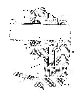
Joints à portée plane montés en tandem, à utiliser dans le cas de pompes centrifuges dotées de joints dynamiques. L'un des joints comporte une lèvre flexible et l'autre, une lèvre non flexible, ce qui assure l'étanchéité à des pressions statiques et dynamiques élevées.


Abrégé anglais


Tandem mounted face seals for use in centrifugal pumps with
dynamic seals. One face seal has a flexible lip and the other face
seal has a non-flexible lip to ensure sealing at high static or
dynamic pressures.

Revendications

Note : Les revendications sont présentées dans la langue officielle dans laquelle elles ont été soumises.


THE EMBODIMENTS OF THE INVENTION IN WHICH AN EXCLUSIVE
PROPERTY OR PRIVILEGE IS CLAIMED ARE DEFINED AS FOLLOWS:
1. Sealing apparatus for use with a dynamic seal
comprising:
a rotatable shaft and said dynamic seal;
a first seal member having a flexible lip mounted on said
shaft;
a fixed gland having a central opening and a gland
chamber, said shaft passing through said central opening with
clearance, and said first seal member being contained within
said chamber and said flexible lip pressing against an
interior wall of said chamber;
a second seal member having a non-flexible lip mounted on
said shaft and axially spaced from said first seal member;
said non-flexible lip pressing against an outside face of
a wall of said chamber separating said first and second seal
members whereby said second seal member functions as a
deflector to propel contaminants away from said first seal
member and prevent leakage from said first seal member at high
pressures; and
said dynamic seal being positioned adjacent said second
seal and distal from said first seal.
2. The apparatus of claim 1 wherein said gland
includes an L-shaped ring member insert forming a portion of
said chamber.
- 7 -

3. The apparatus of claim 1 wherein said first seal
member effectively seals at static pressures from zero to 5
psi.
4. The apparatus of claim 3 wherein said first seal
member is a rubber type material.
5. The apparatus of claim 1 wherein said second seal
member is made of a polymer type material.
6. The apparatus of claim 1 wherein if said first seal
starts to leak at high pressure, the differential pressure
between the area of said chamber and the area of said second
seal will force said second seal against the outside wall face
of said chamber and prevent leakage in the direction away from
said dynamic seal.
7. The apparatus of claim 6 including a sleeve member
on said shaft for mounting said first seal and said second
seal, and said sleeve abutting a rotational member of said
dynamic seal means.
8. The apparatus of claim 3 wherein said second seal
effectively prevents leakage at pressure greater that 20 psi.
9. In a pump having a dynamic seal, sealing apparatus
comprising:
a rotatable shaft and said dynamic seal;
- 8 -

a first seal member having a flexible lip mounted on said
shaft;
a fixed gland having central opening and a box like
chamber, said shaft passing through said central opening with
clearance, and said first seal member being contained within
said chamber and said flexible lip pressing against an
interior wall of said boxlike chamber;
a second seal member having a non-flexible lip mounted on
said shaft and axially spaced from said first seal member;
said non-flexible lip pressing against an outside face of
a wall of said box like chamber separating said first and
second seal members, whereby said second seal member functions
as a flinger-deflector to propel contaminants away from said
first seal member and prevent leakage from said first seal
member at high pressure; and
said dynamic seal positioned adjacent said second seal
member and distal from said first seal member.
10. The apparatus of claim 9 wherein said fist seal
member effectively seals at static pressure form zero to 5
psi.
11. The apparatus of claim 10 wherein said first seal
member is a rubber type material.
12. The apparatus of claim 10 wherein said second seal
member is made of a polymer type material and is effective for
sealing at least up to 30 psi.
- 9 -

13. The apparatus of claim 12 wherein if said first
seal starts to leak at high pressure, the differential
pressure between the area of said chamber and the area of said
second seal will force said second seal against the outside
wall face of said chamber and prevent leakage in the direction
away from said dynamic seal.
14. Sealing apparatus comprising in combination:
a shaft rotatably mounted;
a flexible lip seal member press mounted on said shaft;
a fixed gland having a central opening and a box like
chamber, formed therein, said shaft passing through said
central opening with clearance, and said flexible lip seal
member being contained within said chamber and said flexible
lip pressing against an interior wall of said chamber;
a non-flexible lip seal member press mounted on said
shaft and axially spaced from said flexible lip seal member;
said non-flexible lip seal member pressing against an
outside face of a wall of said chamber separating said first
and second seal members, whereby said non-flexible lip seal
member functions as a deflector to propel contaminants away
from said flexible lip seal member to prevent leakage at high
pressures;
dynamic seal means positioned adjacent the said of said
non-flexible lip seal member;
said flexible lip seal member is made of a rubber type
material and effectively seals at pressures from zero to 5
psi; and
said non-flexible lip seal member is made of a polymer
type material and is effective for scaling at least up to
pressures of 30 psi.
- 10 -

Description

Note : Les descriptions sont présentées dans la langue officielle dans laquelle elles ont été soumises.


20211~i~
Korenblit-l
BACKGROUND 0~ THE INVENTION
The invention relates to pump seals, and more particularly to a
static seal arrangement for centrifugal pumps with dynamic seal
arrangements.
Arrangements of flexible face seals are known from U.S. Patent
Nos. 3,713,659; 3,504,917; 4,311,315; and 3,016,251. These seal
arrangements are designed to seal at relatively low pressures, so
that at pressures higher than 20 psi, the flexible lip is easily
damaged with resultant leakage.
Patent No. 4,186,929 shows another type arrangement with a
conventional lip seal, a non-flexible washer, and a flexible
member. The conventional lip seal requires lubrication, and the
flexible members run with a relatively big axial gap. At static
conditions, the axial gap will get packed with contaminants. When
pressure occurs, it forces contaminants into the lip seal area. In
addition, the flexible member does not perform effectively because
of the axial gap.
Other seal arrangements showing the state of the art are U.S.
Patent Nos. 623,127; 3,284,145; 3,588,129; and 4,509,773. Various
face seal arrangements of the prior art are shown in U.S. Patent
Nos. 3,207,521; 3,771,799; 4,186,929; 2,368,137; 2,990,220;
3,612,547; and 3,727,923.
The tandem mounted face seals are an advance over the prior art
arrangements represented above, and provide a novel solution to
overcome severe application problems where high static or dynamic
pressure occurs.

2 0 2 1 1 5 7
SUMMARY OF THE INVENTION
It is an object of the lnvention to provlde a
improved arrangement tandem mounted face seals for pumps.
Another object of the lnventlon ls to provlde tandem
mounted pump face seals, wlth one seal flexlble and another
seal less or non-flexlble.
Accordlng to a broad aspect, the lnventlon provldes
seallng apparatus for use wlth a dynamlc seal comprislng: a
rotatable shaft and sald dynamlc seal; a flrst seal member
havlng a flexlble llp mounted on sald shaft; a flxed gland
havlng a central openlng and a gland chamber, sald shaft
passlng through sald central openlng wlth clearance, and sald
flrst seal member belng contalned wlthln sald chamber and said
flexlble llp presslng agalnst an lnterlor wall of sald
chamber; a second seal member having a non-flexlble lip
mounted on sald shaft and axlally spaced from sald flrst seal
member; sald non-flexible llp presslng agalnst an outslde face
of a wall of sald chamber separatlng sald flrst and second
seal members whereby sald second seal member functlons as a
deflector to propel contamlnants away from sald flrst seal
member and prevent leakage from sald flrst seal member at high
pressures; and sald dynamlc seal belng posltloned ad~acent
sald second seal and distal from sald flrst seal.
The face seal wlth the flexlble llp preforms the
prlmary seallng functlon and the face seal wlth the non-
flexlble llp functlons as a deflector durlng rotatlon of a
pump lmpeller to prevent leakage at the flexlble llp when hlgh
statlc or dynamlc pressures occur.
-- 3
72432-54
B

2 G 2 1 ~ 5 7
A feature of the invention is that the tandem
mounted face seals are mounted between the dynamic seal
arrangement and the frame of a centrifugal pump.
- 3a -
72432-54

2021~7
Korenblit-l
BRIEF DESCRIPTION OF THE DRAWING
Other features and obJects of the invention will become
apparent by reference to the following description taken in
conjunction with the accompanying drawing which illustrates the
tandem seal arrangement of the invention.

20 2 ~ ~ 5 7
DETAILED DESCRIPTION OF THE PREFERRED EMBODIMENT
In the drawing, an impeller shaft 10 is mounted
thereon a first stage expeller 12 and a second stage expeller
14 whlch coact with end plate 16 and inner plate 18 to form in
a known manner a two stage dynamic seal 20. Gland 22 ls
fastened to end plate 16 and may be fabricated from steel,
bronze, or brass material. Gland 22 includes a gland insert
24 which may be of simllar material. Gland 22 and gland
insert 24 are spaced from shaft sleeve 26 to permit passage of
the shaft through the central opening.
A flexible llp face seal 28 ls press mounted on
shaft sleeve 26 wlthln gland chamber 30 formed by the gland 22
and insert 24. A non-flexible llp face seal 32 is also press
mounted on shaft sleeve 26. The llp of seal 28 ls positioned
to press firmly against counter face 29, and the lip of seal
32 is posltioned to press firmly against counter face 33. One
end of shaft sleave 26 abuts the second stage expeller 14.
One type of seal suitable to perform the function of
the flexible tip face seal is a Forsheda V-ring seal.
(Forsheda Shaft Seal Corporation, Cleveland, Ohio) made from a
rubber grade material, for example, Nitrile, Neopren, Vitron.
One type of ~eal suitable to perform the function of the non-
flexlble tlp face seal is a Checkseal (Greene, Tweed & Co.,
Northwales, Pa), made from, for example a polymer material
such as a carboxylate nitrlle, fluoroelastomer, or ethylene
propylene depending on the service conditions.
Pump frame portion 34 forms part of the dynamic seal
cavity 35, and dynamic seal stuffing box portion 36 is
-- 5
72432-54

2 ~ 5 7
.~
positioned between the impeller housing (not shown) and the
frame 34. Dynamic seal stuffing box portion 36 is connected
to the pump housing as are plates 16, 18.
In operation the face seal 2a wlth the flexible lip
performs the primary sealing function. The flexible lip face
seal seals at low static pressures from O to 5 psi. The non-
flexible lip face seal functions as a flinger-deflector during
rotation of the impeller to propel contaminatlon away from
seal 28 to protect seal 28 from high pressures at least up to
30 psi. If high pressure
- 5a -
72432-54

2 0 ~ ~ ~ 5 7
occurs and seal 28 starts to leak, the differential pressure
created between the two seals 28, 32 will force seal 32
against the counter face 33 to prevent leakage.
The foregoing described a unique tandem seal
arrangement, one flexible and another non-flexible seal.
Material of the non-flexible seal is selected depending on the
maximum static pressure which can occur during the pumping
operation. The flexible seal is installed in the box like
enclosure of the gland, and the non-flexible is run against
the outside surface of the box like enclosure. Both of the
face seals are self-adjusting, shaft mounted and used to
deflect and exclude cont~m;n~nts such as dust, dirt, mud and
water migrating from the impeller housing to the stuffing box.
Both seals are easily mounted on and rotate with the impeller
shaft. The seals self-adjust after several rotations of the
impeller shaft. It will be readily understood by those
skilled in the art that the tandem seal arrangement of the
invention is most suitable for severe applications where high
static or dynamic pressure occurs.
While I have described the principles of my inven-
tion in connection with specific apparatus, it is to be
clearly understood that this description is made only by way
of example, and not as a limitation to the scope of the
invention as set forth in the objects thereof and in the
accompanying claims.
72432-54
-,~
.~ I'g,

Dessin représentatif
Une figure unique qui représente un dessin illustrant l'invention.
États administratifs

2024-08-01 : Dans le cadre de la transition vers les Brevets de nouvelle génération (BNG), la base de données sur les brevets canadiens (BDBC) contient désormais un Historique d'événement plus détaillé, qui reproduit le Journal des événements de notre nouvelle solution interne.

Veuillez noter que les événements débutant par « Inactive : » se réfèrent à des événements qui ne sont plus utilisés dans notre nouvelle solution interne.

Pour une meilleure compréhension de l'état de la demande ou brevet qui figure sur cette page, la rubrique Mise en garde , et les descriptions de Brevet , Historique d'événement , Taxes périodiques et Historique des paiements devraient être consultées.

Historique d'événement

Description Date
Le délai pour l'annulation est expiré 2006-07-13
Inactive : CIB de MCD 2006-03-11
Lettre envoyée 2005-07-13
Accordé par délivrance 1997-10-21
Inactive : Dem. traitée sur TS dès date d'ent. journal 1997-08-14
Inactive : Renseign. sur l'état - Complets dès date d'ent. journ. 1997-08-14
Préoctroi 1997-06-20
Un avis d'acceptation est envoyé 1997-01-21
Toutes les exigences pour l'examen - jugée conforme 1992-05-11
Exigences pour une requête d'examen - jugée conforme 1992-05-11
Demande publiée (accessible au public) 1991-01-15

Historique d'abandonnement

Il n'y a pas d'historique d'abandonnement

Taxes périodiques

Le dernier paiement a été reçu le 1997-06-17

Avis : Si le paiement en totalité n'a pas été reçu au plus tard à la date indiquée, une taxe supplémentaire peut être imposée, soit une des taxes suivantes :

  • taxe de rétablissement ;
  • taxe pour paiement en souffrance ; ou
  • taxe additionnelle pour le renversement d'une péremption réputée.

Les taxes sur les brevets sont ajustées au 1er janvier de chaque année. Les montants ci-dessus sont les montants actuels s'ils sont reçus au plus tard le 31 décembre de l'année en cours.
Veuillez vous référer à la page web des taxes sur les brevets de l'OPIC pour voir tous les montants actuels des taxes.

Historique des taxes

Type de taxes Anniversaire Échéance Date payée
TM (demande, 7e anniv.) - générale 07 1997-07-14 1997-06-17
Taxe finale - générale 1997-06-20
TM (brevet, 8e anniv.) - générale 1998-07-13 1998-06-15
TM (brevet, 9e anniv.) - générale 1999-07-13 1999-06-16
TM (brevet, 10e anniv.) - générale 2000-07-13 2000-06-15
TM (brevet, 11e anniv.) - générale 2001-07-13 2001-06-18
TM (brevet, 12e anniv.) - générale 2002-07-15 2002-06-18
TM (brevet, 13e anniv.) - générale 2003-07-14 2003-06-16
TM (brevet, 14e anniv.) - générale 2004-07-13 2004-05-25
Titulaires au dossier

Les titulaires actuels et antérieures au dossier sont affichés en ordre alphabétique.

Titulaires actuels au dossier
ITT CORPORATION
Titulaires antérieures au dossier
IZYA KORENBLIT
Les propriétaires antérieurs qui ne figurent pas dans la liste des « Propriétaires au dossier » apparaîtront dans d'autres documents au dossier.
Documents

Pour visionner les fichiers sélectionnés, entrer le code reCAPTCHA :


Pour visualiser une image, cliquer sur un lien dans la colonne description du document (Temporairement non-disponible). Pour télécharger l'image (les images), cliquer l'une ou plusieurs cases à cocher dans la première colonne et ensuite cliquer sur le bouton "Télécharger sélection en format PDF (archive Zip)" ou le bouton "Télécharger sélection (en un fichier PDF fusionné)".

Liste des documents de brevet publiés et non publiés sur la BDBC .

Si vous avez des difficultés à accéder au contenu, veuillez communiquer avec le Centre de services à la clientèle au 1-866-997-1936, ou envoyer un courriel au Centre de service à la clientèle de l'OPIC.

({010=Tous les documents, 020=Au moment du dépôt, 030=Au moment de la mise à la disponibilité du public, 040=À la délivrance, 050=Examen, 060=Correspondance reçue, 070=Divers, 080=Correspondance envoyée, 090=Paiement})


Description du
Document 
Date
(aaaa-mm-jj) 
Nombre de pages   Taille de l'image (Ko) 
Abrégé 1993-11-05 1 8
Description 1997-01-20 7 192
Dessins 1997-01-20 1 49
Revendications 1997-01-20 4 138
Revendications 1993-11-05 2 68
Description 1993-11-05 5 147
Dessins 1993-11-05 1 45
Dessin représentatif 1997-10-13 1 23
Avis concernant la taxe de maintien 2005-09-06 1 172
Taxes 1996-06-17 1 54
Taxes 1995-06-14 1 52
Taxes 1994-06-15 1 34
Taxes 1993-06-14 1 26
Taxes 1992-04-27 1 33
Correspondance de la poursuite 1992-05-10 1 32
Correspondance de la poursuite 1997-05-20 1 39
Correspondance de la poursuite 1996-11-05 2 41
Demande de l'examinateur 1996-09-19 2 55
Correspondance de la poursuite 1996-08-29 2 54
Demande de l'examinateur 1996-06-20 2 64
Courtoisie - Lettre du bureau 1992-06-02 1 36
Correspondance reliée au PCT 1997-06-19 1 29