Sélection de la langue

Search

Sommaire du brevet 2021460 

Énoncé de désistement de responsabilité concernant l'information provenant de tiers

Une partie des informations de ce site Web a été fournie par des sources externes. Le gouvernement du Canada n'assume aucune responsabilité concernant la précision, l'actualité ou la fiabilité des informations fournies par les sources externes. Les utilisateurs qui désirent employer cette information devraient consulter directement la source des informations. Le contenu fourni par les sources externes n'est pas assujetti aux exigences sur les langues officielles, la protection des renseignements personnels et l'accessibilité.

Disponibilité de l'Abrégé et des Revendications

L'apparition de différences dans le texte et l'image des Revendications et de l'Abrégé dépend du moment auquel le document est publié. Les textes des Revendications et de l'Abrégé sont affichés :

  • lorsque la demande peut être examinée par le public;
  • lorsque le brevet est émis (délivrance).
(12) Brevet: (11) CA 2021460
(54) Titre français: BLOC DE COMMANDE PAR ENGRENAGE MODIFIE
(54) Titre anglais: GEAR DRIVE UNIT WITH MODIFICATIONS
Statut: Périmé et au-delà du délai pour l’annulation
Données bibliographiques
(51) Classification internationale des brevets (CIB):
  • F16H 03/083 (2006.01)
(72) Inventeurs :
  • EDWARDS, DOUGLAS F. (Etats-Unis d'Amérique)
(73) Titulaires :
  • DANA CORPORATION
(71) Demandeurs :
  • DANA CORPORATION (Etats-Unis d'Amérique)
(74) Agent:
(74) Co-agent:
(45) Délivré: 2000-11-21
(22) Date de dépôt: 1990-07-18
(41) Mise à la disponibilité du public: 1991-01-28
Requête d'examen: 1997-09-23
Licence disponible: S.O.
Cédé au domaine public: S.O.
(25) Langue des documents déposés: Anglais

Traité de coopération en matière de brevets (PCT): Non

(30) Données de priorité de la demande:
Numéro de la demande Pays / territoire Date
07/386,515 (Etats-Unis d'Amérique) 1989-07-27

Abrégés

Abrégé anglais


A transaxle or gear drive unit with ar improved shift
mechanism and gear drive is set forth. The shift mechanism
is of the shift key type and certain gears have recesses to
receive a lug of the shift key with the recesses having ramps
which depress the lug when the key is shifted. One of the gears
has a smooth bore adjacent the recesses to serve as a neutral
position for the shift key. A wide gear having teeth or splines
around its periphery extending the length thereof is rotatably
mounted on one shaft of the gear drive unit. The wide gear
has a plurality of additional gears affixed thereto fox
simultaneous rotation. The wide gear extends beyond the
additional gears and connects with a forward speed gear and
a reverse gear on another shaft. The wide gear thus functions
as a mechanical connection for the additional gears as well
as serving as a gear itself.

Revendications

Note : Les revendications sont présentées dans la langue officielle dans laquelle elles ont été soumises.


I CLAIM:
1. A two-shaft gear drive unit comprising a first shaft,
a first forward speed gear rotatably mounted on said first
shaft, said first gear having a first bore therethrough and a
first recess in said bore, a reverse gear rotatably mounted on
said shaft adjacent said first gear and having a second bore
with a second recess, said second recess opening at a face of
said reverse gear opposite the side adjacent said first forward
speed gear, said second recess having a ramp extending angularly
from the bottom of the recess toward said first forward speed
gear, and terminating at said second bore of said reverse gear,
said second bore beyond said ramp having a smooth and unbroken
portion, whereby said smooth and unbroken portion constitutes
a neutral position for a shift key, a shift key mounted for
longitudinal movement with respect to said first shaft, and
being selectively engagable with said first recess of said first
Forward speed gear, said smooth and unbroken portion of said
second bore, and said second recess of said reverse gear, said
drive unit having a second shaft which is para11e1 to said
first shaft, a wide gear with a smooth bore rotatably mounted
on said second shaft, said wide gear having a plurality of
teeth extending the length thereof and uniformly spaced around
the periphery thereof, a second forward speed gear mounted for
non-rotatable movement on said wide gear, and said wide gear
having a portion of its peripheral teeth engaged with means
engaging said reverse gear.
-11-

2. A gear drive unit according to claim 1 wherein said
wide gear has a second portion of its peripheral teeth, adjacent
the first portion of its peripheral teeth, engaged with said
first forward speed gear.
3. A gear drive unit according to claim 2 wherein said
second portion of said wide gear is between the first portion
thereof and said second forward speed gear.
4. A gear drive unit according to claim 1 wherein said
second forward speed gear has a central hole with teeth meshing
with the peripheral teeth of said wide gear.
5. A gear drive unit according to claim 1 wherein said
smooth and unbroken portion of said reverse gear constitutes
from thirty percent to seventy percent of the thickness of
said reverse gear.
-12-

6. A gear drive unit comprising a shaft, a first forward
speed gear rotatably mounted on said shaft, said first gear
having a first bore therethrough and a first recess in said
bore, a reverse gear rotatably mounted on said shaft adjacent
said first gear, and having a second bore therethrough with a
second recess, said second recess opening at a side of said
reverse gear opposite the side adjacent said forward speed gear
and terminating at said second bore, said second bore beyond said
second recess having a smooth and unbroken portion, whereby said
smooth and unbroken portion of said bore constitutes a neutral
position for a shift key, and a shift key mounted for longitudinal
movement with respect to said shaft, and being selectively
engagable with the recess of said first forward speed gear, said
smooth and unbroken portion of said second bore, and said second
recess of said reverse gear.
7. A gear drive unit according to claim 6 wherein said
gear drive unit has a housing, a bushing is mounted in said
housing, an end of said shaft is rotatably supported by said
bushing, and said shaft has a longitudinal groove extending
completely to the end of said shaft and receives said shift key.
-13-

8. A gear drive unit according to claim 6 wherein said
gear drive unit has a combination gear rotatably mounted on
said shaft on the side of said first gear opposite said reverse
gear, said combination gear has a driven bevel gear and a
structurally-integral, additional forward speed gear, said
combination gear has a third bore extending therethrough with a
third recess therein opening at a side of said combination gear
facing toward said first forward speed gear.
9. A gear drive unit according to claim 8 wherein an inner
end of said third recess is blunt, without a ramp.
10. A gear drive unit according to claim 6 wherein said
smooth and unbroken portion of said second bore constitutes from
thirty percent to seventy percent of the thickness of said
reverse gear.
11. A gear drive unit according to claim 6 wherein said
smooth and unbroken portion of said second bore constitutes
from forty percent to fifty percent of the thickness of said
reverse gear.
12. A gear drive unit according to claim 6 wherein said
gear drive unit further comprises a second shaft, a wide gear
with a smooth bore rotatably mounted on said second shaft, said
wide gear having a plurality of teeth extending the length
thereof and uniformly spaced around the periphery thereof, a
second forward speed gear mounted for non-rotatable movement
on said wide gear, and said wide gear having a portion of its
peripheral teeth engaged with means engaging said reverse gear.
-14-

13. A gear drive unit according to claim 12 wherein said
wide gear has a second portion of its peripheral teeth engaged
with said first forward speed gear,
14. A gear drive unit according to claim 13 wherein said
second portion of said wide gear is between the first portion
thereof and said second forward speed gear.
15. A gear drive unit according to claim 12 wherein said
second forward speed gear has a central hole with teeth meshing
with the peripheral teeth of said wide gear.
-15-

16. A two-shaft gear drive unit comprising a first shaft,
a first forward speed gear mounted on said first shaft, a
reverse gear mounted on said first shaft adjacent said first
gear, a second shaft which is parallel to said first shaft, a
wide gear with a smooth bore rotatably mounted on said second
shaft, said wide gear having a plurality of teeth extending
the length thereof and uniformly spaced around the periphery
thereof, a second forward speed gear mounted for non-rotatable
movement on said wide gear, and said wide gear having a portion
of its peripheral teeth engaged with means engaging said
reverse gear.
17. A gear drive unit according to claim 16 wherein said
wide gear has a second portion of its peripheral teeth engaged
with said first forward speed gear.
18. A gear drive unit according to claim 17 wherein said
second portion of said wide gear is between the first portion
thereof and said second forward speed gear.
-16-

19. A gear drive unit according to claim 16 wherein said
first forward speed gear has a first bore therethrough and a
first recess in said bore, said reverse gear has a second bore
therethrough with a second recess, said second recess opening
at a side of said reverse gear opposite the side adjacent said
first forward speed gear, said second recess having a ramp
extending angularly from the bottom of the recess toward said
first forward speed gear, and terminating at said second bore,
said second bare beyond said ramp having a smooth and unbroken
portion, whereby said smooth and unbroken portion of said bore
constitutes a neutral position for a shift key, and a shift key
mounted for longitudinal movement with respect to said shaft,
and being selectively engagable with the recess of said first
forward speed gear, said smooth and unbroken portion of said
second bore, and said second recess of said reverse gear.
20. A gear drive unit according to claim 16 wherein said
gear drive unit has an additional second forward speed gear
mounted for non-rotatable movement on said wide gear adjacent
said second forward speed gear.
21. A gear drive unit according to claim 20 wherein said
second forward speed gear and said additional second forward
speed gear have central holes with teeth meshing with the
peripheral teeth of said wide gear.
-17-

Description

Note : Les descriptions sont présentées dans la langue officielle dans laquelle elles ont été soumises.


~~ ~~~'~.~~~
This invention relates to a two-shaft transaxle or gear
drive unit with improvements in the shift mechanism and the
gear drive.
S ~ A transaxle according to the invention has only two
parallel shafts, thereby reducing the costs of the unit. A
I plurality of first forward speed gears and a first reverse
ear are individually rotatably mounted on a first shaft within
g
a housing, with the gears having bores with .recesses. A shift
member is rotatable with the first shaft and is selectively
engagable with the recesses to cause the individual gears to
be selectively individually rotated with the first shaft.
More specifically, each of the first forward speed gears and
I the first reverse gear has a plurality of the recesses uniformly
spaced circumferentially axound the bore to receive a lug of
a shift key so that the particular gear rotates with the first
shaft when the shift key lug is in one of the recesses. The
recesses have ramps extending in common directions from the
bottoms of the recesses toward common faces of the gears. The
~ ram s force the shift ke lug toward a retracted position when
p Y
the key moves from one gear to another, in order to prevent
two gears from being engaged at the same time. Furthex, the
reverse gear has a smooth bore next to its recesses, which
bore serves as a neutral position fox the shift key, without
~ any additional collar or ring being required 'to provide neutral.
A plurality of second forward speed gears and a second
reverse gear are supported on a second or output shaft. The
II -Z-

_ II
second forward speed gears mesh with the First forward speed
gears and the second reverse gear is connected through an
intermediate idler gear with the first reverse gear. A11 of
the second forward speed gears rotate together through a wide
gear on which they are affixed. The wide gear extends beyond
the second forward speed gears and constitutes the second
reverse gear. In a preferred form, the wide gear also. meshes
with one of the forward speed gears on the first shaft so that
the wide gear sexves as a second reverse gear, a second forward
j~ speed gear, and a splined shaft which rotatably connects all
of the other second forward speed gears.
It is, therefore, a principal object of the invention to
provide a gear unit with an improved shift mechanism and an
improved gear drive.
Another object of the invention is to provide a two-shaft
transaxle in which a plurality of forward speed gears rotate
together on a wide gear or splined shaft which also functions
as at least one additional gear,
Yet another object of the invention is to provide a gear
drive unit having a plurality of gars mounted on a shaft and
having recesses engaged by a shift key, with one of the gears
~ also having a smooth bore which serves as a neutral position.
Many other objects and advantages of the invention will
be apparent from the following detailed description of a
II -3-

II
preferred embodiment thereof, reference being made to the
accompanying drawings, in which:
Fig. 1 is a somewhat schematic plan view, with parts in
section, of a transaxle embodying the invention, with an upper
~~ housing part removed;
Fig. 2 is an enlarged, fragmentary view in section of
shift mechanism of the transaxle o~ Fig. 1;
Fig. 3 is a view in perspective of certain gears and a
connecting wide gear of the transaxle; and
(I Fig. 4 is an enlarged view in transverse cross section of
the gear components shown in Fig. 3.
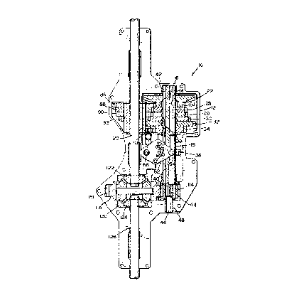
Referring particularly to Fig. 1, a gear drive unit or
transaxle 10 in accordance with the invention includes a housing
12, only a lower part or half of which is shown, the upper part
being removed. The transaxle has at1 input shaft ~-4 and a drive
bevel gear 16, both shown in dotted lines. The input shaft
extends through the upper part of the housing 12 and can be
driven by any suitable means, such as a pulley (not shown)
affixed thereto and driven through a belt by a pulley mounted
on an engine of a small vehicle with which the transaxle is
used. The transaxle also has a first or intermediate shaft 18
and a second or output shaft or~.aXle 20.
A combination driven bevel gear 22 is rotatably supported
on the shaft 18 and is driven by the drive bevel gear 16. A
first forward speed gear or toothed member 24 is structurally
integral and rotates with the driven bevel gear 22. Additional
~~ -'~-

first, forward speed gears or toothed members 26, 28, 30, and
32 are also rotatably supported on the shaft 18 and are
separate from one another. A first reverse gear or toothed
member 34 is adjacent the forward speed gear 32 and is also
rotatably supported on the shaft 18,
The first forward speed gears 24-32 and the reverse gear
34 axe selectively individually rotated~with the shaft 18 by
shift mechanism generally indicated at 36.. The shift mechanism
includes a pair of diametrically-opposite shift or draw keys 38
(see also Fig. 2) which are slidably mounted an diametrically-
opposite, longitudinal grooves 40 in the shaft 18. In a pre-
ferred form, the grooves 40 extend from one end of the shaft
18, located in a bushing 42 mounted in the housing 12, toward
the other end to a reduced splined portion 44 on the shaft 18,
This enables the grooves 40 to be machined substantially more
easily in the shaft 18. Further, the shaft 18 is of constant
diameter from the end in the bushing 42 to the reduced splined
portion 44. Beyond the splined portion, the shaft 18 has a
smooth cylindrical end portion 46 xeceived in a bushing 48
mounted in the housing 12.
Each of the shift keys 38 has a resilient shank 50 with a
lug 52 at one end and a projection 54 at the other end. The
shift key shank 50 is resilient and urges the lug 52 outwardly,
away from the gxoove 40, as is well known in the art. The
projection 54 is received in an inner annular groove 56 of a
shaft collar 58 which also has an outer annular groove 60.
~~ -5-

II
Both of the shift keys 38 are moved longitudinally of the shaft
18 through the shift collar 58 by a decent plate 62 located
above the collar and having a downwardly-extending projection
64 which is received in the outer groove 60. The detent plate
62 is affixed to a shift shaft 66 which extends through and is
rotatably supported by the upper part of the housing 12. The
shaft 66 is connected to a suitable shift arm or lever above
the transaxle which is turned to turn the detent plate 62 to
move the collar 58 along the shaft 18. A shift plate of this
general nature is shown and described in U.S. patent 4,656,886,
issued April 14, 1987, and will not be discussed in further
detail.
When each of the shift keys 38 is moved longitudinally
of the shaft 18, the lug 52 selectively engages xecesses or
notches 68 in bores 70 of the gears 26-32 to individually
connect them with the shaft 18 so as to rotate therewith. The
bore 70 of each of the gears has four of the recesses 68 which
are the same size and shape and axe uniformly positioned around
the bore 70, at ninety degree angles from one another. Each
of the recesses 68 has a bottom 72, side walls 74, and a ramp
76 extending angularly upwardly toward commow faces of the
gears and toward a common end of the shaft 18. This angle
is from thirty degrees to sixty degrees with respect to the
recess bottom 72 and preferably from forty degrees to fifty
degrees. The ramps cart have arcuate and beveled surfaces as
discussed more fully in U.S, patent ~Io. .4,7021119, issued
October 27, 1987. Other patents which show gears with various
3Q II -6-

_. ~ ~~~~~~~o
forms of notches are It. S, patent 735,012, issued July 28, 1903;
French patent No. 423,694 dated April, 1911; and U.S, patent
3,890,850, issued June 24, 1975.
I~ In accordance with the invention, the reverse gear 34
also has recesses 78 in a bore 80 thereof, which recesses can
be of the same size and shape as the recesses 68 in the gears
26-32. However, the reverse gear 34 is thicker, in this
instance, having an extension hub 82 facing away from the for-
I ward gear 32. The smooth portion of the bore 80 beyond the
recesses constitutes from thirty percent to seventy percent of
the thickness of the gear 34 and preferably from forty percent
to sixty percent o~ the thickness of the gear. In this manner,
the smooth portion of the bore 80, located between the notches
15~~ 78 in the gear 34 and the notches 68 in 'the gear 32, constitutes
a neutral position for the shift key 38 and specifically for
the lug 52 thereof, between reverse and forward. In this
manner, no separate collax or ring ox the like is needed to
provide a neutral position for~the shift key. This reduces
~~ production costs by eliminating a part and likewise reduces
assembly costs and time.
The combination geax 22 has conventional recesses or
notches 84 formed therein to receive the key lug 52 when the key
~ is in its extreme right hand position, the inner ends of these
recesses being blunt or squared off without ramps.
II -7-

n
Four second, forward speed gears or toothed members 86,
88, 90, and 92 are rotatably supported by the output shaft or
axle ZO and mesh, respectively, with: the first four fowaxd
speed gears 24, 26, 28, and 30. All of the gears 24-34 and
j~ 86-92 have conventional, involute-shaped gear teeth, in the
preferred form. zn accordance with the invention, the four
gears 86-92 axe mounted together for non-rotatable movement
relative to one another by a thick ox wide spur geax or splined
shaft 94 (Figs. 3 and 4) the width or length of which substan-
tially exceeds the combined width of the four gears 86-92. The
wide gear 94, in this instance, has twelve involute gear tes~th
or splines 96 around the periphery thereof and extending thxough-
out its length. The four gears 86-92 have central holes 98-104
of similar size and shape to the gear 94 and mesh with the
~~ periphery thereof to lock all four of the gears 86-92 together
for simultaneous rotation.
An intermediate portion 106 (Fig. 4) of the gear 94 adjacent
the gear 92 meshes with the first foward speed gear 32 (Fag. 1)
I! to constitute a fifth, second forward speed gear. Finally, an
end portion 108 (Fig. 4) of the wide gear 94 meshes with an idlez
gear 110 (Fig. 1)' which, in turn, meshes with the fixst reverse
gear 34 so that the end portion 108 of the gear 94 constitutes
a second reverse gear. Consequently, it°will be seen that the
(I wide gear 94 serves as a splined shaft for engaging the four
second forward speed gears 86-92, serves as a fifth, second
forward speed gear by engaging the forward speed gear 32, and
serves as a second reverse gear by connecting to the reverse
II -8-

gear 34 through the reverse idler gear 110. The wide gear 94
has a smooth bore 112 throughout its length by means of which
the gear is xotatably supported on the output shaft 20.
j~ A drive pinion gear or toothed member 114 is affixed to
the splined portion 44 of the shaft 18 and rotates therewith.
The gear 114 meshes with and drives a ring gear 116 which is
located around a hausing or suppoxting member 118 of a differ-
ential 120. This can be the type shown in U.S. patent 4,662,241,
~~ issued May 5, 1987, or in U.S. patent 4,232,569, issued Novem-
ber 11, 1980. The differential includes bevel or miter gears
122 and 124 which axe affixed to an end of the output shaft 20
and an end of another output shaft 126, respectively. The
shafts 20 and 126 are axially aligned and are considered to
1S ~~ be one shaft. If a differential is not used, the ring gear 116
can be suitable affixed to both ends of the shafts 20 and 126
to cause them to be driven together as a single shaft.
In the operation of the transaxle, when the lug S2 of the
shift key 38 engages the notch 84 of the combination gear 22,
the pinion Brave gear 114 is driven dixectly through the shaft
18. The gear 114 thereby rotates the ping gear 116 and the
output shaft 20 at a first forward speed. when the lug 52
engages the recess 68 of the first forward speed gear 26, the
drive is through the second forward speed gears 86 and 88,
which rotate together on the wide gear 94, and back through,
the first gear 26 which is connected with the shaft 18 and
rotates the drive pinion gear 114 at a second forward speed.
3A Il -9-

r.~~~~.~.~~
With the lug 52 in the recess 68 of the first forward speed
gear 28, a third forward speed is attained through the gears
24, 86, 90, and 28. With the lug in the recess of the first
forward speed gear 30, as chown, the drive is then through
~~ the gears 24, 86, 92, and 30. When the lug 52 is engaged in
the recess of the first fortaard speed gear 32, the drive is
then through the gear 24, the gear 86, the wide gear 94 and the
gear 32.
~~ With the lug 52 in the neutral bore 80 of the reverse
gear 34, as shown in Fig. 2, the transaxle is in neutral.
Finally, with the lug 52 engaged in the recess 78 of the first
reverse gear 34, the dxive is through the gears 24 and 86,
through the portion 108 of the wide gear 94, and through the
~ idler 110 and the first reverse gear 34 to drive the shaft 18
and the drive pinion gear 114 in the opposite direction.
Various modifications of the above described embodiment
of the invention will be apparent to those skilled in the art,
~~ and it is to be understood that such modifications can be made
without departing from the scope of the invention, if they are
within the spirit and the tenor of the accompanying claims.
30 II -10-

Dessin représentatif
Une figure unique qui représente un dessin illustrant l'invention.
États administratifs

2024-08-01 : Dans le cadre de la transition vers les Brevets de nouvelle génération (BNG), la base de données sur les brevets canadiens (BDBC) contient désormais un Historique d'événement plus détaillé, qui reproduit le Journal des événements de notre nouvelle solution interne.

Veuillez noter que les événements débutant par « Inactive : » se réfèrent à des événements qui ne sont plus utilisés dans notre nouvelle solution interne.

Pour une meilleure compréhension de l'état de la demande ou brevet qui figure sur cette page, la rubrique Mise en garde , et les descriptions de Brevet , Historique d'événement , Taxes périodiques et Historique des paiements devraient être consultées.

Historique d'événement

Description Date
Lettre envoyée 2004-02-20
Le délai pour l'annulation est expiré 2002-07-18
Lettre envoyée 2001-07-18
Accordé par délivrance 2000-11-21
Inactive : Page couverture publiée 2000-11-20
Préoctroi 2000-08-23
Inactive : Taxe finale reçue 2000-08-23
Un avis d'acceptation est envoyé 2000-02-25
Lettre envoyée 2000-02-25
Un avis d'acceptation est envoyé 2000-02-25
Inactive : Approuvée aux fins d'acceptation (AFA) 2000-02-11
Lettre envoyée 1998-02-13
Inactive : Dem. traitée sur TS dès date d'ent. journal 1998-02-13
Inactive : Renseign. sur l'état - Complets dès date d'ent. journ. 1998-02-13
Lettre envoyée 1997-11-19
Lettre envoyée 1997-10-03
Exigences de rétablissement - réputé conforme pour tous les motifs d'abandon 1997-09-23
Exigences pour une requête d'examen - jugée conforme 1997-09-23
Toutes les exigences pour l'examen - jugée conforme 1997-09-23
Exigences de rétablissement - réputé conforme pour tous les motifs d'abandon 1997-09-23
Réputée abandonnée - omission de répondre à un avis sur les taxes pour le maintien en état 1997-07-18
Inactive : Abandon.-RE+surtaxe impayées-Corr envoyée 1997-07-18
Demande publiée (accessible au public) 1991-01-28

Historique d'abandonnement

Date d'abandonnement Raison Date de rétablissement
1997-07-18

Taxes périodiques

Le dernier paiement a été reçu le 2000-06-12

Avis : Si le paiement en totalité n'a pas été reçu au plus tard à la date indiquée, une taxe supplémentaire peut être imposée, soit une des taxes suivantes :

  • taxe de rétablissement ;
  • taxe pour paiement en souffrance ; ou
  • taxe additionnelle pour le renversement d'une péremption réputée.

Les taxes sur les brevets sont ajustées au 1er janvier de chaque année. Les montants ci-dessus sont les montants actuels s'ils sont reçus au plus tard le 31 décembre de l'année en cours.
Veuillez vous référer à la page web des taxes sur les brevets de l'OPIC pour voir tous les montants actuels des taxes.

Historique des taxes

Type de taxes Anniversaire Échéance Date payée
1997-09-23
TM (demande, 7e anniv.) - générale 07 1997-07-18 1997-09-23
Rétablissement 1997-09-23
Requête d'examen - générale 1997-09-23
TM (demande, 8e anniv.) - générale 08 1998-07-20 1998-06-30
TM (demande, 9e anniv.) - générale 09 1999-07-19 1999-06-21
TM (demande, 10e anniv.) - générale 10 2000-07-18 2000-06-12
Taxe finale - générale 2000-08-23
Titulaires au dossier

Les titulaires actuels et antérieures au dossier sont affichés en ordre alphabétique.

Titulaires actuels au dossier
DANA CORPORATION
Titulaires antérieures au dossier
DOUGLAS F. EDWARDS
Les propriétaires antérieurs qui ne figurent pas dans la liste des « Propriétaires au dossier » apparaîtront dans d'autres documents au dossier.
Documents

Pour visionner les fichiers sélectionnés, entrer le code reCAPTCHA :


Pour visualiser une image, cliquer sur un lien dans la colonne description du document. Pour télécharger l'image (les images), cliquer l'une ou plusieurs cases à cocher dans la première colonne et ensuite cliquer sur le bouton "Télécharger sélection en format PDF (archive Zip)" ou le bouton "Télécharger sélection (en un fichier PDF fusionné)".

Liste des documents de brevet publiés et non publiés sur la BDBC .

Si vous avez des difficultés à accéder au contenu, veuillez communiquer avec le Centre de services à la clientèle au 1-866-997-1936, ou envoyer un courriel au Centre de service à la clientèle de l'OPIC.


Description du
Document 
Date
(aaaa-mm-jj) 
Nombre de pages   Taille de l'image (Ko) 
Abrégé 1993-11-12 1 23
Revendications 1993-11-12 7 188
Description 1993-11-12 9 311
Dessins 1993-11-12 3 101
Dessin représentatif 1999-07-14 1 41
Dessin représentatif 2000-11-05 1 24
Courtoisie - Lettre d'abandon (taxe de maintien en état) 1997-09-28 1 188
Avis de retablissement 1997-10-02 1 172
Avis de retablissement 1997-11-18 1 172
Courtoisie - Lettre d'abandon (requête d'examen) 1997-10-13 1 172
Accusé de réception de la requête d'examen 1998-02-12 1 179
Avis du commissaire - Demande jugée acceptable 2000-02-24 1 166
Avis concernant la taxe de maintien 2001-08-14 1 179
Correspondance 2000-08-22 1 84
Correspondance 1993-12-30 4 124
Taxes 1993-08-23 4 152
Taxes 1997-09-22 1 42
Correspondance 2004-02-19 1 18
Taxes 1996-05-30 1 38
Taxes 1995-07-04 1 36
Taxes 1994-06-08 1 32
Taxes 1993-11-24 1 23
Taxes 1992-01-06 1 21