Note : Les descriptions sont présentées dans la langue officielle dans laquelle elles ont été soumises.
~l 2~217
...;-i
1 Backgrnund Qf the Invention
~; I Ice fishing is a popular winter pastime and devices for
use in such fishing have been much improved in recent times.
A typical device employs a support having a post to
which a line carrying reel is rotatably connected with the suppor
6 enabling the device to be positioned at or over a hole through
f"`i 7 the ice with the baited hook at a selected depth. A length of a
S straight, narrow spring has one end connected to the post and a
9 signal flag attached to its other end. When the device is ready
for use with enough line pulled from the reel to place the baited
11 hook at a selected depth, the spring is manually curved to an
12 extent enabling it to be releasably connected in one way or anoth
13 er to the reel or the line in order to free the spring when a
14 fish takes the bait with the flag then elevated to signal that -
~ lS event.
`~` 16 Difficulties experienced with devices of the above ~-
17 described type are that the lines often become caught as holes
f 18 freeze over and that the flag carrying spring often becomes
19 accidentally released giving a false signal to the angler. Wind
is a common but not the only cause of such false signals.
21 In earlier devices, the reels were located to be above
22 water, but as ~he lines extending downwardly through the holes
23 frequently became locked in ice, if the temperature was low
24 enough, later devices, when set up for use, had their reels
positioned to be below the surface of the wa~er. Each such
-3-
~, , , .. ,~,, 4~.;
.,,j ~
~ ~ l ~ ~2~17~
l later device had its flag carrying spring releasably held by a
~ 2 trip extending downwardly through a tube and exposed to be re-
f,`~ 3 leasably connected to the reel by a trip mechanism. While the
~ 4 ¦ lines of such devices dld not become frozen in the hole in very
;~i, 5 cold weather, the water in the tubes freezes rendering the trip
6 mechanisms inoperable. In acldition, it lemained necessary to
7 keep each hole open in the event of a hooked fish or to enable
8 the condition of the bait to be checked. In addition, the signal
flags often WeTe accidentally released as the trip mechanisms
--~l 10 were not positively held.
!! ~ 1 1 . ~ _
;~ 12 The general objective of the present invention is to
~¦ 13 provide ice fishing devices which better meet ice fishing require .
f'''' 14 ments than do those currently in use.
; 15 One aspect of the invention is the manner in which the
~ 16 free end of the conventional narrow, straight spring, carrying
!~ 17 the signal flag, is caught and held until the reel is turned in
18 I a line unwinding direction.
191 An ice fishing device incorporating this feature of
20 ¦ the invention has a post provided with a support by which it can
21 ¦ be held in a position of use at a hole through the ice. The
22 ¦ line carrying reel is rotatably connected to the post with the
23 side wall of the reel proximate to the post spaced therefrom to
24 provide a gap into which a reel latch extends to be caught and
ZS~ held by a atch with which the free end of the spring is
,, l
~ . .,~,. ....
~'
r'~
~; ~~ ' : ' ~ ' ' . j .
'~' ' :~
l ~
f 1 provided.
When the device is to be used, a length of line is
3 withdrawn from the reel adequate to place the baited hook at a
4 selected depth when entered through the hole in ~he ice. The
'`J,;~, 5 spring is then manually curved in the appropriate direction and
`~ 6 to the appropriate extent to enable its catch to engage and
~ 7 hold the latch until the reel has been turned in a line unwind-
:'3 8 ing direction to a predetermined extent.
In one embodiment of the invention, the latch is a
10 cylindrical stud fixed on ~he reel wall that is or is to be
11 j proximate to the post and spaced from the reel axis. In another
12 embodiment, the latch is a tear or pear shaped cam with the wider
13 end thereof arcuate with respect to the axis of rotation of the
. 14 reel. In any case, the catch and latch are shaped and dimension-
lS ed for mutual engagement at points, spaced apart arcuately with
~, 16 respect to the reel from about 60~ as a minimum with the
-~ 17 maximum less than 180. :
;~ 18 Another aspect of the invention is the support of the
19 posts of ice fishing devices. In accordance with the invention, -~
20 each support is a hole cover in the form of a thermally insulated
, 21 container having a central passageway through which *he hook
22 and line may freely be passed and an offset socket in its upper
"1 23 surface shaped and dimensioned to receive and hold the
24 appropriate end of the post. The under surface of the container
25 is provided with a depending wall d-imensioned to fit within the
. 1.,
,", ..... . . ~ . -
: . ~
~ j l 2 ~ 2 1 7 t~
: ',
i~ 1 hole in the ice then to hold the support from sliding out of
2 position. Such a support is light in weight and, due to its
3 'insulation, maintains a hole in the ice free for long periods
even in severe weather.
Brief DescriptiQn of the Drawings
`~ 6 The accompanying drawings illustrate preferred embodi-
ments of ice fishing devices in accordance with the invention of
8 which
9 Figure l is a perspective view of a device in
accordance with one embodiment of the invention
ll positioned for use over a hole in the ice;
12 Figure 2 is an edge view of the device;
13 Figure 3 is a side view of the device;
14 Figure 4 is a view of the device as seen from above;
?'~ 15 Figure 5 is a view of the reel, on an increase in
16 scale and taken approximately along the indicated
,t~ 17 line 5--5 of Figure 2;
18 Figure 6 is a sectional view of the reel taken
approximately along the indicated line 6--6 of
, .? 20 Figure 5;
21 Figure 7 is a section taken substantially along the
22 indicated line 7--7 of Figure 3; .
23 Figure 8 is a view, similar to Figure 1, illustrating .
24 another embodiment of the invention; .
Figure 9 is a section, on- an increase in scale taken :
i ? 6 .
,',`.~,7
~ 1 ap~roximately along the indicated line 9--9 of
?.;'' 2 Figure 8; and
,;.~,.7 3 Figure 10 is a section ~aken generally along the indi-
4 cated line 10--10 of Figure 9.
The Preferred Embodimen~ o the l~YentiOn
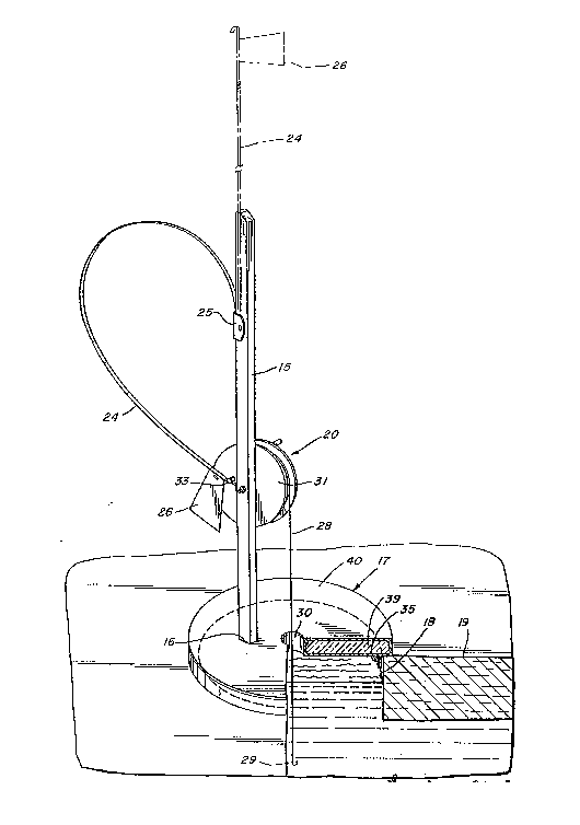
The ice fislling de~ice illustrated by Figures 1 - 7
8 has a post 15 removably sea~ed in a socket 16 in the upper sur-
face of a support, generally indicated at 17 and shown as a type
9 covering a hole 18 through the ice 19. ¦
A reel, generally indicated at 20 is rotatably mounted ¦ -
11 i on a bolt 21 which serves as an axle and extends through a
12 middle portion of the post 15 and is secured by a nut 22. Be-
13 tween the p~st 15 and the reel 20, the bolt 21 is provided with
14 a series of fiber washers 23 which both space the reel a wanted
distance from the post and serve as an adjusta'ole drag.
16 A normally straight, narrow length 24 of spring steel
17 has one end attached to a holder Z5 slidably secured to the
18 post 15 in a conventlonal manner. A signal flag 26 is fastened
t~, 19 to the other end of the spring steel length which terminates in
¦ 20 an arcuate catch 27.
21 The reel 20 has a line 28 wound thereon to the free
22 end of which a fish hook 29 is attached. The support 17 is
23 shown as an insulated hole cover with its construction later
24 detailed, see Figure 7 and has a central hole 30 dimensioned to
enable the line and fish hook freel-y to pass there through.
-7-
~ ~ y ;~; , ; ,, I ~ ~
~ - .
` -~ 2 ~ 2 ~
1 The socket 16 is so located that the line from the reel does not
2 engage the sides of the hole 30 in the support 17 when fishing
at n~rmal depths. That one of its side walls 31, on the post
side of the reel 20 has a cylindrical latch 32 dimensioned to
5 avoid contact with the post 15 as the reel 20 turns and is
;~`i 6 provided with a flange 33 at its free end.
The latch 32, when the device is set for use with the
~ fish hook 29 at a wanted depth is caught by so bending the spring
steel length 24 that its catch 27 can engage and hold the latch
10 32 and the end wall 33 of which holds the catch against the
11 action of the biased spring steel length (see Figure 4). The
~i 12 reel 20 is thus held from turning until there is a definite,
~ 13 sustained pull on the line in an unwinding direction with the
;~j 14 latch 32 freed on a partial turning of the reel, typically, in
15 the disclosed embodiments slightly in excess of 90.
~l 16 The support 17, see Figure 7, consists of a bottom
~ 17 part 34 having a depending flange 35 on its undersurface spaced
;~; 18 inwardly of the side wall 36 and dimensioned to fit freely
;~ 19 within the upper part of ~he hole 18 in the ice to prevent the
3 20 support from sliding out of position. The bottom part 34 has a
21 central sleeve 37 establishing the hole 30 and also has the
~-i 22 socket 16 fo~ the post. The side wall 36, and the walls of the
23 socket and sleeve have inwardly disposed lips 38, and after the
24 bottom part has been filled with insulation 39, the cover 40 is
~" 25 pressed in place with its locking flanges 41 snapped over the
.,,'
.~ .
-~?,
2~21 7.~:1
1 lips 37 to securely lock the cover in place against the entrance
2 of water.
4 ~`he embodi~ent of the invention illustrated by
Figures 8 - 10 is generally s:imilar to that of Figures 1 - 7 and
will not be described in detail except as to differing features.
Corresponding parts9 however, are identified by the appropriate
7 reference numerals which are distinguished by the suffix addition
8 "A"
9 ~ In this embodiment, the arcuate latch is in the form of
a cam 42 shown as appToximately pear or tear shaped with its
j wider part or base 43 semi-circular and co-axial with the axis of
12 the reel 20A, and its sides 44 substantially straight. The
13 catch 27A at the free end of the spring steel length 24A is caugh
14 about the base 43 of the cam 42 when the device is set. The cam
42 has an end flange 45 to prevent the bias of the spring 24A
16 from disengaging the catch 27A. As will be apparent from
17 Figure 9, when the reel 20A has been partly turned, approximately
18 90, the catch 27A is released. In this embodiment, a spring 46
19 serves as a spacer between the post 15A and the reel 20A and as
an adjustable drag.
21 ~ While the use of ice fishing devices in accordance with
22 the invention will be apparent from the foregoing, it will be
23 appreciated that the devices are well adapted for use. The
24 supports of a set of devices may be tied together through the ~;~
central holes. As is conventional,- the slides to which the
~ ~, g : ~
, ";~
ll 2~'7~ ~ 1
1 ~ spring steel lengths are connected are slid downwardly to bring
~,2 I the flags against the posts for convenience in carrying them.
~;3 'In use, the devices can be quickly assembled and then with
~:sufficient line pulled from the reel and passed through the holes
in the appropriate ones of the supports and the hook baited,
.~6 each device may be placed in position with its support covering
7~ the hole to delay the freezing of water therein for long inter-
.jl8 vals even in sub zero weather and prevent snow from being blown
~9 therein.
.~10 Each device is set by bending the spring steel length
~,11 to an extent enabling the catch thereof to be caught by the
:112 latch and so securely held that it cannot be disengaged by strong
13 winds but becomes easily disengaged by the pull of a fish once
````I14 it has taken the bait in a manner causing the reel to turn
~¦ , 15 through a suùstantial arc.
`3,' '
. ~
`~ .
~:~ I `
,~, ` -10- 1