Note : Les descriptions sont présentées dans la langue officielle dans laquelle elles ont été soumises.
UK9-89-031 - 1 - 2 3
DISPLAY SYSTEM
The present invention relates to a display system
including apparatus for defining a boundary which
encloses a filled image area stored in a display memory.
The filled image area can be part of an image presented
by means which are dependent on the nature of the display
system. Common image output devices are printers and
displays.
For the purpose of explanation, and to highlight a
particular application of the invention, a computer
system including a display device for which the image is
resolved into a two dimensional array of picture elements
(pixels) will be described. Each pixel can therefore be
represented by a bit stored in a bit map arranged within
a memory which is part of the display system. A display
system can be a computer system itself, or an optional,
peripheral adapter, such as a display adapter card,
installed in a computer system.
For simplicity of explanation, a process by which
bits are either set or not set in order to define a
boundary or area in a display memory is referred to as a
drawing process.
A display system is commonly utilized to Jill areas
of a displayed image, such as slices of a pie chart for
instance, with a particular color or shading pattern.
This is commonly achieved by means ox a boundary defined
area fill process.
In order to correctly fill an area area boundary
segments should be drawn according to a set of general
rules which can be summarized as follows :
a) A new area boundary pixel status is determined
according to an exclusive-or function by which a new
boundary pixel is combined with a current boundary pixel.
I
UK9-89-031 - 2 -
by If an area boundary segment has a positive gradient,
the second pixel in the segment is not set, Similarly, if
an area boundary segment has a negative gradient, the
first pixel in the segment is not set.
c) If an area boundary segment has a shallow gradient,
and is therefore composed of horizontal runs of adjacent
pixels, the first pixel ox the segment only is set if the
gradient is positive and the second pixel of the segment
only is set it the gradient is negative.
d) If an area boundary segment is horizontal, the
pixels composing the segment are not set. An area
boundary segment specified by a single pixel is rejected
in a similar fashion.
Failure to adhere to such rules causes an area
filling procedure to start or stop unpredictably or in
incorrect locations within the destination bit map.
EP-A-0145821 describes an area boundary drawing
procedure implemented by a combination of hardware and
software and the area fill procedure is implemented by
hardware. More specifically, it describes an area filling
procedure for a graphics displaying computer system in
which, in order to draw filled areas, additional control
logic is supplied to define an outline of the area in an
auxiliary memory using Bresenham's Algorithm. Area
filling logic consisting of exclusive Or gates is used to
fill the enclosed area in the refresh buffer as the
enclosing outline is read from the auxiliary memory. A
combination of hardware and software is used to examine
each line segment and either reject it according to
conventional rules or define it with the appropriate Y
direction, swapping end points if necessary.
Such a process is suitable for drawing an area
boundary specified by a succession of single line
segments. However, problems arise when the the area
boundary includes complex curves. In such cases, it is
UK9-89-031 - 3 - 2
not necessarily possible to simply swap end points to
ensure a consistent drawing direction, since a general
curve may have some sections moving up the image whilst
other sections are moving down.
The aim of the preserlt invention therefore is to
enable boundary lines to be drawn in any direction, in
accordance with the aforementioned general boundary
drawing rules.
According to the present invention there is now
proposed, a computer graphics system having display logic
comprising a destination bit map containing a plurality
of image bits which map to a plurality of pixels for
presenting an image, an auxiliary bit map containing a
plurality of area boundary bits representing pixels
defining an area boundary line which encloses an area of
the image, area filling logic for operating upon those
image bits enclosed by the area boundary line in order to
fill the area with a particular pattern and color,
characterized in that the display logic further comprises
area boundary drawing logic having line segmentation
means to resolve the specified boundary line into a
plurality of intersecting two pixel line segments which
can, from that time forward, be operated upon separately
to define the area boundary bits in accordance with
conventional area boundary drawing rules.
In accordance with the present invention , therefore
that an area boundary line, for drawing in an auxiliary
bit map, can be constructed from intersecting two pucks
line segments. An analogy can be drawn between a two
pixel line segment of the Line and a link in a bicycle
chain. The link is connected to an adjacent link by a
rivet which is common to both links. A pixel in the
construction of the line can therefore be likened to a
rivet in the bicycle chair
Preferably, the area boundary drawing logic includes
pixel resolving logic for resolving a two pixel line
UK9-89-031 - 4 -
segment into a first pixel and a second pixel which can
from that time forward be operated upon separately in
order to define the area boundary bits in accordance with
conventional area fill boundary drawing rules.
This arrangement has the advantage that, at any one
time, the area fill boundary drawing logic is processing
a two pixel line segment rather than a line segment
composed of a larger number of pixels. Logical operations
associated with boundary line drawing are thus
simplified. It follows therefore that the area fill
boundary drawing logic circuitry can be less complicated
in construction. This, in turn, reduces the time taken
for the computer graphics system to process area fill
boundary line data. Furthermore, such a technique can be
applied to general incremental line drawing algorithms
for image generation, such as Bresenham's run length
algorithm, wherein horizontal runs of pixels are produced
rather than single pixel steps
In one particularly preferred arrangement, the area
boundary drawing logic has direction determining logic
for determining a direction of extension of the specified
boundary as introduced by a two pixel line segment and
for operating upon the first pixel and the second pixel
accordingly. This has -the advantage that the area
boundary can be drawn in the auxiliary bit map in any
direction, without modifying the area boundary line, by
swapping end points for instance.
In the following, an example of a logic circuit in
accordance with the present invention will be described
with the aid of the following diagrams in which:
figure 1 is a block diagram of a computer system
including a display system.
Figure 2 is a block diagram of boundary defined area
filling hardware for the display system.
Figure 3 is a block diagram of area boundary drawing
logic for defining a two pixel line segment.
Jo
UK9-89-031 - 5 -
Figure 4 illustrates eight orientations of a two
pixel line segment.
Figure 5 is a table relating eight orientations of a
two pixel line segment to a bit for pixel representation.
Figure 6 shows a typical section of an area boundary
line, for drawing in an auxiliary bit map, subdivided
into a set of two pixel line segments.
Figure 7 shows a typical line defined according to a
run length algorithm for drawing in a bit map, subdivided
into a set of two pixel line segments and horizontal
pixel runs.
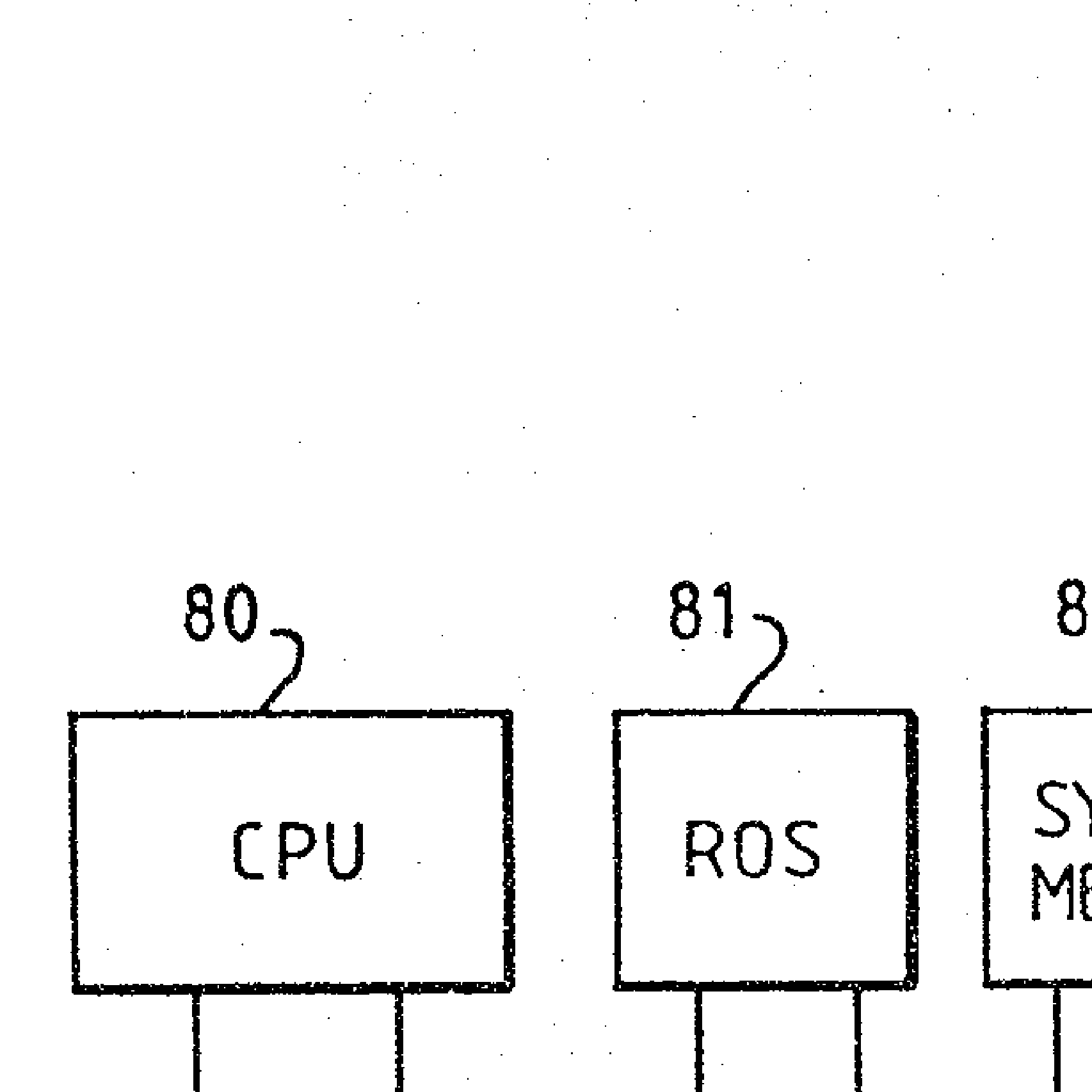
Figure 1 illustrates an example of a computer system
for graphics data processing. Figure 3 shows such a
computer system. The computer system includes a central
processing unit (CPU) (80) for executing programmed
instructions involving the data. A bus architecture (86)
provides a data communication path between the CPU and
other components of the computer system. A read only
memory (ROW) (81) provides secure storage of data. A
random access system memory ~823 provides temporary data
storage. Data communication with a host computer system
(93) is provided by a communication (COMMA) adapter (85).
on I/O adapter (84) enables data to pass between the bus
architecture and a peripheral device such as a disc file
(83). A user can operate the computer system using a
keyboard (91) which is connected to the bus architecture
via a keyboard adapter (90). A display device (88)
provides a visual output from the computer system. The
visual output is generated by a display System (92) which
can be split into a display memory (89) and processing
logic (87).
-
The processing logic contains boundary defined area
filling hardware for operating upon image data stored in
the display memory. Some functions of the boundary
defined area filling hardware will now be described with
reference to the block diagram shown in figure 2.
:
UK9-89-031 - 6 - I f3
Initially, an area boundary I is drawn in an
auxiliary bit map (1) which is part of a display memory.
This task is performed by boundary drawing logic I in
response to graphics data supplied to the display system
via -the bus architecture. The display memory also
contains a separate, destination bit map (11) for storing
bit patterns representative of pixel components of a
displayed image. A one for one mapping can be defined
between the auxiliary bit map and the destination bit
map. A rectangular section (2) of the auxiliary bit map
encloses the area boundary. This rectangular section is
sequentially scanned (6), bit row by bit row, from left
to right, by area scanning and filling logic (7). The
area scanning and filling logic simultaneously scans (8)
a rectangular section (10) of the destination bit map
corresponding to that in the auxiliary bit map. The left
hand edge of the rectangular section is on the outside of
the area boundary. Accordingly, the area scanning and
filling logic therefore ignores this region ox the
destination bit map. However, when the area boundary is
crossed, the area scanning and filling logic begins an
area filling procedure for drawing a filled area ~12) in
the destination bit map. When the area boundary is next
crossed, the area filling procedure stops. This process
repeats until the right hand edge of the rectangle is
reached. Each bit row in the scan rectangle is scanned in
a similar manner. In order to prevent adjacent filled
areas from overlapping therefore, the boundary defined
area filling process operates on the destination bit map
so that a boundary is included in any left hand edge of a
filled area but excluded from any right hand edge. For
the purpose of illustration, a drawn pixel is indicated
in figure 2 by ~*11, while a null pixel is indicated by
" . " .
An example of area boundary drawing logic arranged
in accordance with the present invention will now be
described with reference to the logic circuit shown in
figure 3.
2 I I
UK9-89-031 - 7 -
This logic circuit is responsive to a 3 bit octane
code (C0,Cl,C2) representation of the two pixel line
segment. The octane code is refreshed in response to a
clock generator signal (60). The first pixel of a two
pixel line segment is potentially drawn if OR gate 61 has
a high output and C2 is high. This causes AND gate I to
have a high output. The second pixel of a two pixel line
segment is potentially drawn if OR gate 61 has a high
output and C2 is low. This causes AND gate 63 to have a
high output. The output of AND gate 63 is stored by
register 64. The register passes its contents to
Exclusive Or gate 65 in response to the clock generator
signal which loads the next octane code. The next octane
code corresponds to the next two pixel line segment to be
processed. Exclusive Or gate 65 combines the output of
AND gate 62, representing the first pixel, with the
output of register 64, representing the second pixel, to
produce a desired pixel bit. The desired pixel bit is
compared with an existing pixel status bit stored in the
auxiliary bit map by and Exclusive Or gate 66. The output
of Exclusive Or gate 66 replaces the existing pixel
status bit with a new status bit.
It will be appreciated that, according to the
present invention, an area boundary line, for drawing in
an auxiliary bit map, can be constructed from
intersecting two pixel line segments. An analogy can be
drawn between a two pixel line segment of the line and a
link in a bicycle chain. The link is connected to an
adjacent link by a rivet which is common to both links. A
pixel in the construction of the line can therefore be
likened to a rivet ill the bicycle chain.
There are eight possible orientations ox a two pixel
line segment. In figure 4, these orientations or
"octanes" are labeled 0 to 7. It follows therefore that
an orientation can be represented, for the purpose of
logic processing, by a three bit octane code. However, it
will be appreciated that, dependent on the boundary
drawing logic provided, such an octane code may be
UK9-89-031 - 8 -
specified by more bits. In a table shown in figure 5,
each orientation of a two pixel line segment corresponds
to a specific three bit octane code. The table also shows
which pixels of the two pixel line segment are to be
drawn to comply with the aforementioned general line
drawing rules. In this sense, the table can be considered
as a truth table on which area boundary drawing logic can
be based in accordance with the present invention.
Two example line types for processing in accordance
with the present invention will now be described.
Figure 6 illustrates a line (30) which is
constructed from fifteen intersecting two pixel line
segments (31). For the purpose of illustration,
successive pixels in the line are assigned to ascending
hexadecimal numbers thereby highlighting interconnections
between two line segments.
Figure 7 illustrates a boundary line drawn by a line
drawing algorithm, such as Bresenham's Run Length
Algorithm. Each iteration of the algorithm produces a
horizontal run of pixels (51) rather than a single pixel.
A step (52) between one horizontal run of pixels and the
next is represented by a two pixel line segment. In this
example there are three horizontal line segments. For
illustration purposes, these are labeled 111,222, and
333). According to the aforementioned general rules, each
horizontal run of pixels is classed as a horizontal line
segment and is therefore rejected by the area boundary
drawing logic. The length of the horizontal line segment
simply identifies the location at which the next pixel is
drawn.