Note : Les descriptions sont présentées dans la langue officielle dans laquelle elles ont été soumises.
~022082
80LENOID OPERATED FLU8H VALVE AND FLOW CONTROL ADA~TER
VALVE IN~ERT THEREFO~
~I~LD OF THF lNv~hlIoN
The present invention is directed to a lavatory flush
valve, and more particularly to a solenoid operated flush
valve which is automatically operated in response to an
electronic sensor.
A conventional lavatory flush valve is a diaphragm-type
valve which is operated by a user by actuation of an external
handle. Upper and lower chambers are separated by a flexible
diaphragm and are filled with water supplied by-a water inlet.
The water outlet is connected to a urinal or the like fixture.
Fluid flow communication between the upper and lower chambers
and the outlet occurs by actuation of the handle and flexing
of the diaphragm. The handle may be replaced with an
appropriate device for causing automatic operation of the
-
~022082
valve.
There is a need for a solenoid operated flush valve and
an easily substitutable flow control adapter valve insert
therefor, which are simple in construction and easy to repair.
OBJECTB AND ~UMMARY OF THE I~VBNTION
The principal object of the present invention is to
provide a retrofit kit permitting a manually operable flush
valve for automatic operation.
Another object of the present invention is to provide a
flow control adapter valve insert for a solenoid operated
flush valve.
Yet another object of the present invention is to provide
a solenoid operated flush valve which is simple in
construction and easy to repair and maintain.
A further object of the present invention is to provide
a solenoid operated flow control adapter valve insert which
can be easily substituted for the manually operated valve
insert generally included in a conventional lavatory flush
valve.
A solenoid operated flush valve has a main flush valve
body including water inlet and outlet means. The main flush
valve body includes generally horizontally extending nipple
means which is in fluid communication with the water inlet and
outlet means. A flow control means is removably mounted
within the nipple means and includes valve insert means and
solenoid means in cooperative engagement with the valve insert
means. The valve insert means includes first and second ends
and a side. The valve insert means includes a first
passageway extending axially between the first and second ends
thereof and a second passageway extending between one of the
first and second ends and the side of the valve insert means,
202~082
The second passageway is in fluid communication with the water
outlet means through the side of the valve insert means.
Means cooperate with the solenoid means for selectively
blocking the second passageway to thereby regulate the flow
of flushing water through the flush valve.
A solenoid operated flow control adapter valve insert for
a flush valve has flow control means that includes valve
insert means and solenoid means in cooperative engagement with
the valve insert means. The valve insert means includes first
and second ends and a side. The valve insert means includes
a first passageway extending axially between the first and
second ends thereof and a second passageway extending between
one of the first and second ends and the side of the valve
insert means. The solenoid means includes a reciprocable
plunger which is movable therein and cooperates with and is
in alignment with the valve insert means for selectively
sealing the second passageway. The plunger moves away from
the valve insert means when the solenoid means is activated
for opening the second passageway.
The method of converting a manual flush valve to an
electrically operated flush valve includes providing solenoid
valve insert means having fluid inlet and fluid outlet means,
a proximity sensor, and means for connecting the insert means
and the sensor to a power source. The manual flush valve
includes a main valve body having water inlet and outlet
means, a generally hori~ontally extending nipple means,
securement means mountable on the nipple means, and a manually
operated valve insert means removably mounted in the nipple
means. The method includes removing the securement means from
the nipple means and then removing the manually operated valve
insert means from the nipple means. The solenoid valve insert
means is then inserted into the nipple means and is positioned
2Q~2082
so that the fluid inlet means extends along a first axis and
the fluid outlet means extends along an axis generally
transverse thereto. The securement means is repositioned on
the nipple means and a proximity sensor is mounted adjacent
the flush valve. The proximity sensor is electrically
connected to the solenoid valve insert means.
BRIEF DE~CRIPTION OF THE DRAWINGB
The above and other objects and advantages and novel
features of the present invention will become apparent from
lo the following detailed description of the preferred embodimentof the invention illustrated in the accompanying drawings,
wherein:
Figure 1 is a fragmentary elevational view partially in
section of the flush valve of the invention shown mounted on
a wall of a lavatory;
Figure 2 is a cross-sectional view taken along lines 2-
2 of Figure 1, with portions omitted for clarity;
Figure 3 is a cross-sectional view taken along lines 3-
3 of Figure 1, with portions omitted for clarity;
Figure 4 is a fragmentary elevational view partially in
section of the flush valve of the present invention in
operation;
Figure 5 is an exploded perspective view of the solenoid
operated adapter valve insert of the invention;
Figure 6 is an enlarged side elevational view of the
portion marked within the circle in Figure 5;
Figure 7 is an enlarged cross-sectional view of the valve
insert of Figure 5; and
Figure 8 is an end elevational view of the valve insert
taken in the direction of arrow X in Figure 7.
~0~82
DETAILED DESCRIPTION OF THE INVENTION
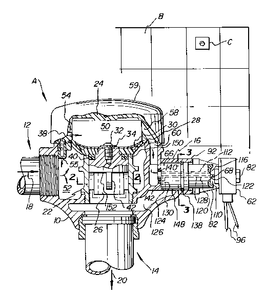
The flush valve A of the present invention, as best shown
in Figure 1 and 4, includes main flush valve body 10 having
water inlet 12 and water outlet 14. Flush valve A is mounted
to lavatory wall B, and is electrically connected to infra-
red sensor assembly C.
The flush valve A further includes a horizontally
extending nipple 16 which is diametrically opposite water
inlet 12 and extends along axis 18. Water outlet 14 extends
lo along longitudinal axis 20 which is transverse to axis 18.
The flush valve body 10 includes a vertically extending
replaceable seat 22 positioned centrally therein coaxial with
water outlet 14. A cast cap 24 is disposed directly above
replaceable seat 22. The replaceable seat 22 is cylindrical
in shape and accommodates slidable diaphragm guide 26. A
diaphragm assembly, including diaphragm 28 made of a flexible
material and resilient washer 30, is mounted atop guide 26 by
screw 32 and fiber gasket 34. As best shown in Figure 4,
diaphragm 28 is securely held in a water-tight manner about
its peripheral edge 36 between cast cap 24 and main valve body
10. A washer 38 and silencer device 40 are disposed below
diaphragm 28.
As best shown in Figures 1 and 2, diaphragm guide 26 is
cylindrical in shape and includes three radially extending
vertical ribs 42 disposed peripherally on guide body 44. Ribs
42 are equiangularly disposed about guide body 44 and abut
internal wall 46 of seat 22. Ribs 42 define flow channels 48.
As best shown in Figure 1 and 4, ribs 42 and channels 48 are
formed generally in the lower half portion of guide 26 such
that when diaphragm 28 is seated on seat 22, no fluid
communication is made between flow channels 48 and water inlet
12.
--` 2~2Q82
The main flush valve body 10 includes upper chamber 50
separated from lower chamber 52 by diaphragm 28. Lower
chamber 52 is in fluid communication with water inlet 12, and
communicates with upper chamber 50 via opening 55 of fill
passageway 54. As best shown in Figure 4, a regulating screw
56 is provided in east cap 24 for controlling the flow of
water through passageway 54. Flush passageway 58 in cast cap
24 is diametrically opposite fill passageway 54 and
communicates with flush chamber 60 in main flush valve body
10. The chamber 60, as best shown in Figures 1 and 4, is in
fluid communieation with nipple 16. A cover 59 is mounted
over cap 24 by a conventional screw 61.
A solenoid operated flow control adapter valve insert
assembly, generally indicated as D and shown in detail in
Figure 5, is inserted in nipple 16 and is in fluid
communication with chamber 60. The adapter assembly D
includes electrically operated solenoid 62 with spool 64 and
generally cylindrical valve insert 66. A generally
cylindrical, T-shaped plunger 68 reciprocally moves within
cylindrical opening 70 of spool 64. The opening 70 does not
extend the length of spool 64, and is closed adjacen~ end face
72 of spool 64. A coil-spring 73 is biased between plunger
68 and end face 72. The spool 64 preferably is made of steel
and has screw-threads 74 on end portion 76 thereof. The
threads 74 engage with corresponding threads 78 in
conventional nut 80. The nut 80 secures spool 64 within
solenoid 62.
The adapter assembly D further includes mounting sleeve
82 with screw-threaded end 84 disposed between spool 64 and
solenoid 62. The sleeve 82 defines a passageway 86 therein
that extends between ends 88 and 90. The passageway 86 has
a diameter greater than the diameter of insert 66, so that
~;., -6-
.~. ~, ,
-
` ~022082
valve insert 66, spool 64, and plunger 68 may easily slide
therein. As best shown in Figures 1 and 4, when adapter
assembly D is mounted within nipple 16, end 84 engages
corresponding screw-threaded end 92 of nipple 16 for mounting
the adapter assembly D therein. In Figure 5, reference
numeral 94 designates a conventional washer that is positioned
between sleeve 82 and solenoid 62. Electric cables 96 connect
solenoid 62 with sensor C.
As best shown in Figure 6, plunger 68 includes at end 98
a resilient gasket 100. Gasket 100 includes chamfered nipple
102 projecting coaxially from gasket 100. When flush valve
A is not in operation, gasket 100 and nipple 102 engage end
104 of insert 66 in a water-tight manner, described below in
more detail.
As best shown in Figure 7, valve insert 66 includes
projection 106 extending coaxially from end 108 and recess 110
extending inwardly from end 104 thereof. A passageway 112
extends between projection 106 and recess 110 and includes
openings 114 and 116. The passageway 112 has a diameter which
is uniform throughout its length. The passageway 112 is in
fluid communication with flush chamber 60 via opening 114 at
one end, and opens into recess 110 by opening 116 at the other
end thereof. It should be noted that although passageway 112
has been shown as extending generally parallel to side 118 of
insert 66, it is well within the scope of the invention to
vary the orientation thereof.
A generally L-shaped passageway 120 extends between end
104 of insert 66 and side 118 thereof, and communicates with
recess 110 via opening 122 at one end, and opens into base
chamber 126 via opening 124 in side 118, at the other end
thereof, as best shown in Figures 1 and 4. The passageway 120
include~ ~ 128 which extends parallel to passageway 112, and
~ ~ -7-
2022082
leg 130 which extends generally transverse thereto. The
passageway 120 has a diameter which i6 uniform throughout its
length, including both legs 128 and 130. The diameter of
passageway 120 corresponds with the diameter of passageway
112. As best shown in Figure 7, leg 128 extends generally
along central longitudinal axis Y of insert 66. On the other
hand, passageway 112 is parallel to and spaced from axis Y,
as best shown in Figure 8. Recess 110 includes inner and
outer angularly disposed perimeter surfaces 132 and 134,
respectively.
As best shown in Figure 7, a radially extending
peripheral groove 136 is provided on valve insert 66 for
accommodating conventional o-ring 138 therein. Another o-ring
14 0 is disposed around projection 106. When the adapter
assembly D is mounted within nipple 16, o-ring 140 seals
opening 142 in flush valve body 10 through which projection
106 extends, and prevents back flow of water from insert 66
to flush chamber 60. Likewise, o-ring 138 substantially seals
and prevents back flow of water from recess 110 to chamber 60.
As best shown in Figure 7, leg 130 of passageway 120 is
disposed between o-rings 138 and 140.
As best shown in Figure 7, valve insert 66 includes
larger diameter section 144 and small diameter section 146.
Preferably, the length of smaller diameter section 146 is less
than the length of larger diameter section 144.
As best shown in Figure 7, leg 128 of passageway 120 runs
the length of smaller diameter section 146 and a portion of
the length of larger diameter section 144. The leg 130 of
passageway 120, however, extends transversely thereto within
larger diameter section 144. Passageway 112 extends through
the length of projection 106, larger diameter section 144 and
the smaller diameter section 146, but short of recess 110.
- - 2D22082
Further, leg 130 of passageway 120 is disposed adjacent
projection 106 and away from recess 110.
As best shown in Figure 3, clearance 148 between nipple
16 and valve insert 66 is provided. Due to clearance 148, it
is not necessary that side opening 124 of L-shaped passageway
120 be aligned with base chamber 126 when the adapter assembly
D is installed in nipple 16 since, when flush valve A is
activated (described below in detail), water from recess 110
will make its way to base chamber 126 through clearance 148.
Therefore, clearance 148 increases the ease of installing
adapter valve assembly D since one need merely insert
assembly D into nipple 16 without being concerned about the
alignment of leg 130 of passageway 120 with base chamber 126.
As best shown in Figure 1 and 4, when the insert assembly
D is installed in nipple 16, passageway 112 and leg 128 of
passageway 120 run generally parallel to nipple 16, while leg
130 of passageway 120 runs generally transverse thereto.
Recess 110 is always full of water, since passageway 112 is
in constant fluid communication with flush chamber 50 and its
opening 116 in recess 110. Passageway 120, on the other hand,
communicates with base chamber 126 and recess 110 via openings
124 and 122, respectively. As a result, retraction of plunger
68 by energization of solenoid 62 causes the water in recess
110 to flow immediately to clearance 148. This assumes that
diaphragm 28 flexes almost instantly in order to cause
operation of the valve D.
USE AND OPERATION
A manually operated flush valve is converted to an
electrically operated flush valve by first removing the
conventional handle assembly (not shown) from its nipple 16.
Then, the solenoid operated flow control adapter valve insert
2022082
assembly D of the invention is inserted into the nipple 16.
The assembly D is positioned in the nipple 16 so that
projection 106 of insert 66 is firmly seated in opening 142
` of valve body 10. As discussed above, it is not necessary
that leg 130 of passageway 120 be aligned so as to open into
base chamber 126. Subsequently, sleeve 82 is screwed tight
on nipple 16, a ~ nut 80 is secured tight over end 76 of spool
64. The cables 96 are then connected to sensor assembly C.
When the flush valve is not in operation, upper and lower
chambers 50 and 52 are filled with water at supply line
pressure. Upper chamber 50 receives water via fill passageway
54 which is in fluid communication with lower chamber 52 via
opening 55. Therefore, the pressures on both sides of
diaphragm 28 are the same and diaphragm 28 remains firmly
seated on upper surface 150 of seat 22, since diaphragm 28 is
biased into the closed position. As shown in Figure 1, upper
chamber 50 is in fluid communication with recess 110 via
passageway 58, chamber 60 and passageway 112. However,
opening 122 of L-shaped passageway 120 is closed because of
abutting plunger 68, and any water present in recess 110 does
not flow to base chamber 126 via passageway 120.
The flush valve A is rendered operative by a lavatory
user stepping in front of sensor assembly C. This transmits
an electrical signal to the solenoid 62 for causing operation
thereof. When solenoid 62 is activated upon receiving the
signal from sensor C, plunger 68 moves within spool 64 away
from valve insert 66, as best shown in Figure 4, and the water
present in recess 11 begins to flow through passageway 120
into base chamber 126 and to water outlet 14.
When the water begins to flow through passageway 112 to
passageway 120 via recess 110, the pressure in upper chamber
50 is reduced, thereby creating a pressure differential with
--10--
-
2022082
lower chamber 52. The differentlal causes diaphragm 28 to be
flexed upwardly, as best shown in Figure 4, thereby permitting
water to flow through flow channels 48 to outlet 14, as shown
by arrows 154 in Figure 4.
When solenoid 62 is deactivated, for example, by the
absence of a user from the field of vision of the sensor C,
plunger 68 reciprocates back to its initial blocking position
due to the force exerted by spring 73. This closes opening
122 of valve insert 66. As a result, the water from chamber
60 and recess 110 stops flowing and begins to accumulate
therein and in upper chamber 50. This causes the pressure in
chamber 50 to rise and eventually be equalized with the
pressure in lower chamber 52. Accordingly, diaphragm 28, due
to the balanced pressure in upper chamber 50 and its internal
bias, returns to its initial blocking position, shown in
Figure 1. the flow channels 48 are no longer in fluid
communication with lower chamber 52 and, therefore, the water
from chamber 52 stops flowing to outlet 14 via flow channels
48.
While this invention has been described as having a
preferred design, it is understood that it is capable of
further modifications, uses and/or adaptations of the
invention and following in general the principle of the
invention and including such departures from the present
disclosure as come within known or customary practice in the
art to which the present invention pertains, and as may be
applied to the central features hereinbefore set forth, and
fall within the scope of the invention or the limits of the
claims appended hereto.