Note : Les descriptions sont présentées dans la langue officielle dans laquelle elles ont été soumises.
202299~
MOTOR vEHICLE POWER SUPPLY DEVICE
BACKGROUND OF THE INVENTION
The present invention relates to a motor vehicle
power supply device for energizing a starter motor when an
engine mounted on a motor vehicle is to be started.
Lead storage batteries are mounted on motor vehi-
cles as a power supply for an engine starter and other elec-
tric loads such as accessories.
When the engine is to be started, electric energy
stored in the lead storage battery is supplied to energize
the starter motor. A pinion gear of the starter motor is
brought into mesh with a ring gear mounted on the crankshaft
of the engine, and rotated to rotate the crankshaft, thereby
starting the engine.
An electric current which is supplied from the bat-
tery to the starter motor when starting the engine is very
high, e.g., 100 A or more, though it is supplied in a short
period of time. The capacity of a battery to be installed
on a motor vehicle is determined primarily in view of its
ability to start the engine. The large electric power which
is consumed to start the engine is supplemented when the
battery is charged by electric power generated by an alter-
nator mounted on the motor vehicle and driven by the engine
while the motor vehicle is running.
satteries mounted on motor vehicles are known lead
batteries as secondary batteries, and they are charged and
-1- ~
`~ 2022996
discharged through a chemical reaction between electrodes
and an electrolytic solutlon. Such a battery can discharge
a large current within a short period of time. The battery
is charged with a current of 10 A or less which is supplied
over a long period of time and through a gradual chemical
reaction. Therefore, if a much larger current is supplied
to charge the battery, the battery would be excessively
heated and the electrodes might be deformed and damaged.
Motor vehicles which are mainly used by commuters
run over short distances, and motor vehicles used as deliv-
ery cars are repeatedly stopped and started highly
frequently. Since these motor vehicles re~uire the engines
to be started frequently and are continuously driven over
short periods of time, the batteries mounted on these motor
vehicles cannot be charged sufficiently enough to make up
for the electric power consumed when the engines are
started. Accordingly, the batteries tend to be used up, or
run down, failing to start the engines.
To solve the above problems, the applicant has pro-
posed a motor vehicle power supply device which has a large-
capacitance capacitor that is charged by a battery mounted
on the motor vehicle and that discharges stored electric
energy to actuate the engine starter to start the ensine 2
2 0 ~
With the proposed motor vehicle power supply
devices, the engine starter is energized by the electric
energy stored in the large-capacitance capacitor. The
large-capacitance capacitor can supply an intensive current.
Therefore, even if the voltage of the battery is somewhat
lowered, the engine may be started by the electric energy
stored in the capacitor. To charge the capacitor after its
stored electric energy has been discharged, a sudden large
current is required since the internal resistance of the
capacitor is small at the time it is charged, and hence the
alternator is sub~ected to a large stress. While the engine
is idling at low temperature, the engine may possibly die if
the load on the alternator is large. If the alternator load
is large, the engine may also not be revved up with a quick
response when the motor vehicle is to be started or
accelerated.
SUMMARY OF THE INVENTION
It is an ob;ect of the present invention to provide
a motor vehicle power supply device which has a large-
capacitance capacitor that can be charged by a battery and
an alternator driven by an engine mounted on a motor
vehicle, the motor vehicle power supply device having means
for reducing adverse effects on operation of the engine at
the time of charging the large-capacitance capacitor.
According to the present invention, there is pro-
vided a motor vehicle power supply device comprising an
2~0~ $
alternator drivable by an engine mounted on a motor vehicle,
a battery chargeable by electric energy generated by the
alternator, a capacitor connected to the alternator and the
battery, charging speed varying means connected between the
capacitor, and the alternator and the battery, for varying
the speed at which the capacitor is charged, detecting means
for detecting an operating condition of the motor vehicle,
and control means for controlling the charging speed varying
means in response to detected signals from the detecting
means.
The above and other objects, features and advan-
tages of the present invention will become more apparent
from the following description when taken in conjunction
with the accompanying drawings in which a preferred embodi-
ment of the present invention is shown by way of illustra-
tive example.
BRIEF DESCRIPTION OF THE DRAWINGS
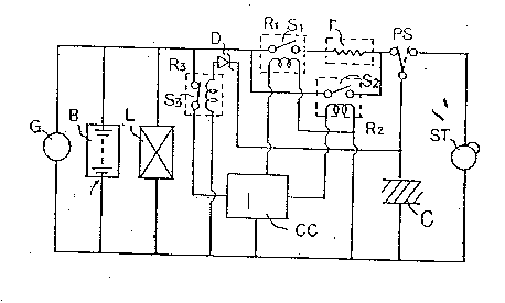
Fig. 1 is a circuit diagram of a motor vehicle
power supply device according to an embodiment of the pre-
sent invention; and
Fig. 2 is a circuit diagram of a control circuit in
the motor vehicle power supply device shown in Fig. 1.
DETAILED DESCRIPTION OF THE PREFERRED EMBODIMENT
As shown in Fig. 1, an alternator G which is driven
by the torque of an engine (not shown) serves as an electric
power source to supply electric energy to a load L on a
2~22~9g~
motor vehicle, charge a battery B, and also charge a large-
capacitance capacitor C.
The capacitor C comprises an electric double layer
capacitor having a large electrostatic capacitance and is of
the wet type employing active carbon and an aqueous
solution. The electric double layer capacitor C has a vol-
ume which is one tenth or smaller of the volume of a conven-
tional aluminum-electrolytic capacitor that has the same
electrostatic capacitance as that of the capacitor C.
Typically, the electric double layer capacitor C has a cap-
acitance ranging from 30 to 50 F (farads). When the engine
is to be started, a power switch PS is shifted as indicated
by the broken line in Fig. 1, supplying electric energy from
the capacitor C to a starter ST to energize the starter ST
with the electric energy which has relatively sharp rising
characteristics.
Relay circuits Rl, R2 are controlled by a control
circuit CC. The relay circuits Rl, R2 have respective con-
tacts Sl, S2 for opening and closing a circuit for charging
the capacitor C. The contact Sl is connected in series with
a resistor r which limits the current that is supplied to
charge the capacitor C. The relay circuits Rl, R2 have
respective coils connected to the control circuit CC.
A relay circuit R3 has a normally closed contact S3
for controlling energization of the control circuit CC. The
relay circuit R3 has a coil connected in series with a zener
202299~
diode D. When the capacitor C is sufficiently charged and
the voltage thereacross is higher than a predetermined
voltage, the contact S3 is opened to de-energize the control
circuit CC, thereby interrupting the control function
thereof.
The control circuit CC serves to vary the time in
which to charge the capacitor C depending on the operating
conditions of the motor vehicle. Fig. 2 shows the control
circuit CC in greater detail. In response to signals from
various switches and sensors that are located in various
parts of the motor vehicle, the control circuit CC selec-
tively energizes the relay circuit Rl or R2.
In Fig. 2, the control circuit CC ls connected to
various switches and sensors. The switches include a gear
position switch SG which is turned on when the transmission
of the motor vehicle is shifted into one of the gear posi-
tions for moving the motor vehicle, an accelerator pedal
switch SA which is turned on when the accelerator pedal is
depressed, and a brake switch SB which is turned on when the
brake pedal is depressed. The sensors include a coolant
temperature sensor SW which is turned on when the tempera-
ture of an engine coolant reaches a predetermined
temperature, and a vehicle speed sensor SS which is turned
on when the speed at which the motor vehicle runs reaches a
predetermined speed. A signal from the gear position switch
SG is applied through an inverter to an AND gate Gl. A sig-
- 6 -
2022g~3~
nal from the accelerator pedal switch SA is applied through
an inverter to the AND gate Gl. A signal from the coolant
temperature sensor SW is applied to the AND gate Gl. The
signal from the accelerator pedal switch SA is also applied
through the inverter to an AND gate G2. A signal from the
vehicle speed sensor SS and a signal from the brake switch
Ss are applied to the AND gate G2. The AND gate Gl has an
output terminal connected to the coil of the relay circuit
R1, whereas the AND gate G2 has an output terminal connected
to the coil of the relay circuit R2.
Operation of the motor vehicle power supply device
according to the present invention will be described below.
In order to charge the capacitor C, the power
switch PS is shifted to a solid-line position shown in Fig.
1. When the motor vehicle is started or accelerated, the
gear position switch SG is turned on since the tr~n~m;ssion
is one of the gear positions for moving the motor vehicle,
and the accelerator pedal switch SA is also turned on since
the accelerator pedal is depressed. Therefore, the output
signals of the AND gates Gl, G2 of the control circuit CC
are low, and the relay circuits Rl, R2 are not energized.
Therefore, electric energy generated by the alternator G is
not supplied to the capacitor C, and the engine is not sub-
~ected to any load which would otherwise be imposed by the
generated electric energy. Therefore, the torque produced
by the engine is consumed to accelerate the motor vehicle.
h~
While the engine is idling, the transmission is in
a neutral position. Therefore, the gear position switch SG
is turned off. The accelerator pedal switch SA is also
turned off since the accelerator pedal is not depressed.
When the temperature of the engine coolant reaches a prede-
termined temperature and the coolant temperature sensor SW
is turned on, the AND gate Gl produces a high output signal
which energizes the relay circuit Rl. Since the contact S1
is closed, the electric energy from the alternator G is sup-
plied through the resistor r, which then supplies a limited
current to charge the capacitor C. Therefore, an abrupt
large current is prevented from being supplied to the capac-
itor C. During the idling of the engine, any load imposed
on the engine by the generation of electric energy by the
alternator G is reduced, and the engine is prevented from
dying.
- when the motor vehicle is decelerated, as long as
the speed of the motor vehicle is higher than a predeter-
mined speed, the vehicle speed sensor SS is turned on. The
accelerator pedal switch SA is turned off as the accelerator
pedal is not depressed, and the brake switch SB is turned on
as the brake pedal is depressed. Therefore, the output sig-
nal from the AND gate G2 is high, thereby energizing the
relay circuit R2. The contact S2 is closed, and the elec-
tric energy from the alternator G is directly supplied to
charge the capacitor C. At this time, the travel of the
20229~6
-
motor vehicle is not adversely affected since the torque of
the engine is sufficiently large during deceleration.
The capacitor C is charged while the engine is
idling or the motor vehicle is being decelerated. When the
voltage across the capacitor C reaches a predetermined volt-
age at the final charging stage, the zener diode D and the
relay circuit R3 are operated to cut off the electric energy
which has been supplied to the control circuit CC. The
capacitor charging control operation of the control circuit
CC is therefore caused to cease.
With the present invention, the magnitude of the
load on the engine is determined depending on the signals
from the switches and sensors that are located in various
parts of the motor vehicle and indicate the operating condi-
tion of the motor vehicle. When the motor vehicle is
started or accelerated, requiring the engine to produce its
output torque, as determined by the determined magnitude of
the engine load, the capacitor C is prevented from being
charged. When the engine torque is sufficiently large as
during deceleration of the motor vehicle, the capacitor C is
charged fully by the electric energy produced by the
alternator. Therefore, the charging circuit is controlled
depending on the operating condition of the motor vehicle.
Any adverse effects which the electric energy for charging
the capacitor has on the operation of the engine are
reduced. As a consequence, the engine is prevented from
202299~
.
dying while it is being idling, and the response of the
engine during acceleration of the motor vehicle is prevented
from becoming slow.
Although a certain preferred embodiment has been
shown and described, it should be understood that many
changes and modifications may be made therein without
departing from the scope of the appended claims.
- 10 -