Note : Les descriptions sont présentées dans la langue officielle dans laquelle elles ont été soumises.
3. Detailed Description of the Invention
Applicable Field of Industry~>
This invention relates to a device for fitting swing-
able items such as a toilet seat and a toilet lid or a
flap lid to an object of fitting (toilet pan).
Prior Art
~ nown devices designed for fitting a toilet seat and
a toilet lid to a toilet pan are normally classified into
types as described below.
One is a type to be used with a toilet pan having a
projection for receiving a horizontal spindle that swing-
ably support a toilet seat and a toilet lid. Another is a
type to be used with a toilet pan having a pair of verti-
cal bores for receiving pins or threaded rods projecting
downward from a hinge connecting a toilet seat and a
toilet lid.
Problems to be Solved by the Invention
However, a device of the former type is accompanied
by the problem of difficulty with which the spindle is
fitted and removed, making itself far from a one-touch
system. Moreover, the projection provided on the toilet
can make an obstacle for cleaning oyeration.
A device of the latter type is also accompanied by
the problem of toilsome operation of fitting and removing
pins or screwed rods, and hence the toilet seat and the
toilet lid. Moreover, since the vertical bores for re-
ceiving pins or screwed rods are not through bores, they
are not easily accessible for cleaning and can store
. ,., ~ ~ .
~ ,,
. ; . ~ . :
.
J !,; ,i ?)
contaminated water. Besides, devices of both the former
and the latter types comprises longs fitting screws,
entailing packaging problems for shipment and transporta-
tion.
In view of the above mentioned problems of the prior
art, it is therefore the object of claim (1) of the inven-
tion to provide a device for removably fitting and a
toilet seat and a toilet lid to a toilet pan without
difficulty that can be packaged for shipment and, once
installed, removed for cleaning with utmost ease.
A device according to claim (2) of the invention is
intended to provide an improved easiness with which a
toilet seat and a toilet lid can be fitted to a toilet
pan. A device according to claim (3) of the invention is
designed to provide an enhanced easiness with which the
devices can be fitted. Finally, a device according to
claim (4) of the invention is designed to provide a pleas~
ant appearance as well as durability and protection
against contamination so say nothing of ease of fitting
operation.
Means for Solving the Problems
According to claim (1) of the inventlon, the above
ob~ects are achieved by providing a device for fitting a
toilet seat and a toilet lid to a toilet pan comprising a
receiving member provided with abutments projecting rear-
ward and having a downwardly inclined upper surface ~or
being removably fitted to the object of fitting, a main
body projecting rearward from a hinge for being tightly
placed on said receiving member, said hinge being swing-
able with the swinging motion of the toilet seat and/or
the toilet lid, the front end of said main body forming an
axis of rotation when removably fitted to the correspond-
ing front end of said receiving member, and a hook verti~
cally swingably disposed at the rear end of said main
body, said hook being biased downward by a spring, said
hook being provided with a tripping members for being
t releasably engaged with the respective abutments of the
receiving member under the spring force of said spring.
, According to claim (2), there is provided a device
~; for fitting a toilet seat and a toilet lid to a toilet pan
comprising a receiving member provided with abutments
projecting rearward and having a downwardly inclined upper
surface for being removably fitted to the object of fit-
ting, a main body projecting rearward from a hinge for
;` being tightly placed on said receiving member, said hinge
being swingable with the swinging motion of the toilet
seat and/or the toilet lid and so arranged that it gener-
ates a desired resistance when its movable shaft is rotat-
. ed by an angle found within a predetermined angle range,
. the front end of said main body forming an axis of rota- r
': ' ' ' ' `
- ~ ~
r '`. '~ ;''' f~ h r~
tion when removably fitted to the corresponding front end
of said receiving mem~er, and a hook vertically swingably
disposed at the rear end of said main body, said hook
being biased downward by a spring, said hook being provid~
ed with a tripping members for being releasably engaged
with the respective abutments of the receiving member
under the spring force of said spring.
According to claim (3), there is provided a device
for fitting a toilet seat and a toilet lid to a toilet pan
comprising a receiving member provided with an abutment
projecting rearward and having a downwardly inclined upper
surface for being removably fitted to the object of fit-
ting, a main body projecting rearward from a hinge for
being tightly placed on said receiving member, said hinge
being swingable with the swinging motion of the toilet
seat and/or the toilet lid, the front end of said main
body forming an axis of rotation when removably fitted to
the corresponding front end of said receiving member, a
hook vertically swingably disposed at the rear end of said
main body by means of a spindle and biased downward by
means of a spring, and a vertically swingable lever coax-
ially disposed at the read end of said hook to contain
within said hook within itself, said lever being provided
with a tripping member for being engaged with said hook to
make it upwardly swingable against the spring force of the
-: ' ' .
- . - ~ .
- ,. - ~ ., -
--
~ J ,.,- ~ " j ~
spring.
According to claim (~), there is provided a device
for fitting a toilet seat and a toilet lid to a toilet pan
comprising a receiving member provided with an abutment
projecting rearward and having a downwardly inclined upper
surface for being removably fitted to the object of fit-
ting, a main body projecting rearward from a hinge for
being tightly placed on said receiving member, said hinge
being swingable with the swinging motion of the toilet
seat and/or the toilet lid, the front end of said main
body forming an axis of rotation when removably fitted to
the corresponding front end of said receiving member, a
hook vertically swingably disposed at the rear end of said
main body by means of a spindle and biased downward by
means of a spring, said hook being provided with a hook
actuating section, and a cover extending from the rear end
of said main body to cover the upper and lateral portions
of said hook.
~<Operation
The receiving member of a device according to claim
(1) is rigidly fitted to the right position of an object
of fitting such as a toilet pan in advance by means of
adhesive.
Through engagement of the front end of said receiving
member and that of the main body, there is formed an axis
.: .. , ~.
.
- ~
.
~,, .,, ;; ,, ' ¦ j, ~;
of rotation, around which the main body is rotated as it
is pressed down (toward th~ receiving member) until the
tripping members of the hook disposed at the front end of
said main body abut the abutments of said receiving mem-
ber. When the main body is pressed further down, said
hook becomes rotated against the spring force of the
spring and, as the upper sur~aces of the abutments are
inclined downward toward the rear end, the tripping mem-
bers slide on said respective surfaces until they are
moved away from the surfaces, when the main body downward-
ly rotates back by the biasing force of the spring so that
the tripping members are engaged ~lith the abutments of the
receiving member and consequently the main body is locked
against further movement as it is flatly placed on the
receiving member.
Since said main body is integrally formed with a
hinge for swingably moving the toilet seat and the toilet
lid, the toilet seat and the toilet lid are swingably
fitted to the toilet pan when the main body is locked by
the receiving member.
For removing the toilet seat and the toilet lid from
the toilet pan, the engagement between the tripping mem-
bers and the abutments can be released by simply li~ting
the hook against the biasing force of the spring. There-
; fora, the hook, the main body and the hinge can be removed
~ . , ' .
~ t'j f ~ r~
from the receiving member without difficulty.
A device according to claim (2) differs from a deviceaccording to claim (1) only in that its receiving member
is anchored to a toilet pan by driving the threaded fit-
ting rods of said receiving member into the corresponding
fitting holes provided on the toilet pan in advance.
Other~ise, it has features similar to those of a device
according to claim (1).
A device according to claim (3) resembles to a device
according to claim (1) only in that the main body is
removably fitted to a receiving member which is rigidly
fitted to the toilet pan in advance but differs from the
latter in that the main body is removed from the receiving
member by rotating the lever upward to rotate the hook,
which is engaged with the tripping member of the lever,
also upward against the resilient force of the spring
until the engagement between the abutment of the receiving
member and the tripping member of the hook is released so
that the hinge and the lever are removed from the receiv-
ing member along with the main body.
A device according to claim t4) resembles to a device
according to claim (3) but is so designed that the lever
can be rotated upward by holding the lever actuating
section of the hook along with the cover section of the
main body and therefore the hook is can be rotated upward
:. ~
against the resilient force of the spring when the lever
is moved upward to release the engagement between its
tripping member and the abutment of the receiving member,
when the main body, the hinge and the hook can be removed
from the receiving member.
Embodiments
Firstly, claim (1) and claim (2) of the invention
will be described further by way of a preferred embodiment
illustrated in the accompanying drawings.
As shown in Eigs. 1 through 4, receiving member 1 of
the embodiment is realized in the form of a thick plate
made of a synthetic resin material provided with a thread-
ed fitting rod 2 projecting perpendicularly downward from
the front area of its lower surface.
Since the illustrated receiving member 1 is rigidly
fitted to an upper edge of a swingable toilet seat by
driving the fitting rod 2 into a fitting hole 4 bored into
the ob~ect of fitting 3, it can be tightly anchored to the
object without looseniny because of the firm engagement
between the thread 2a formed on the outer periphery of
said fitting rod 2 and the thread formed on ~he inner
periphery of the fitting hole 4.
Alternatively, said receiving member 1 may be rigidly
fitted to the pan by means of adhesive without using a
fitting rod 2. Said receiving member 1 is provided with a
.. . .
. , - ~ , .
.. . . .
- ~ ,, - '
.. :
'. ' ~ '
~J ; ~J _, 3 J
pair of abutments 5, 5 at its rear end.
Each of said abutments 5, 5 has an inclined upper
surface 5a sloping down from its base area toward the tip
and a substantially horizontal abutting surface Sb formed
on its bottom and extending to the tip.
Said receiving member 1 is provided on its front side
with a horizontal (laterally extending) groove 6 for
receiving a spindle that makes the axis of swinging move-
ment of a main body 7 which will be described below.
Said main body 7 to be removably fitted to said
receiving member 1 has a top wall 7a, a rear side wall 1a,
a front side wall 7c and a pair of lateral side walls 7d,
7d, all side walls being directly connected to said top
I wall 7a, said main body 7 having an inversely U-shaped
plan view and beinq so formed that it can be stably placed
on and received by said receiving member.
Said main body 7 is integrally formed with and pro-
jecting rearwardly from hinge case 8a of a hinge 8.
While the hinge 8 may be an ordinary but or flap
hinge, it is, in this embodiment, a damping hinge compris-
ing a hinge case 8a, though which a rotatable shaft 8b is
so arranged that it is rotated with a toilet seat and a
toilet lid and said case 8a contains viscous fluid within
the space between said case 8a and the rotatable shaft 8b
so that the viscous shearing resistance of the viscous
.
~: ' ' ` ' ' ' ' '
?., ~` 2 ~ rj
fluid and the resilient force of a spring (not shown)
provide a certain resistive force that appropriately
dampen any abrupt movement of the toilet seat and/or
toilet lid that may collide against the upper edge of the
toilet pan with impact.
A notch 7e is formed at the rear end of said main
body 7 along its longitudinal center line to separate its
rear side wall 7b into to parts, in which a hook 9 is
arranged and supported by a spindle 10 realized in the
form of a hollow pin in such a manner that it can be
vertically pivoted around the shaft.
Said hook 9 has a horizontal upper surface 9a and an
inclined lower surface 9b sloping upward from its front
end toward the rear end so that it has a pair of substan-
tially triangular side walls. A horizontal and lateral
spindle bore 9c is arranged near the front end of the hook
9 so that it is pivotally supported by said spindle 10
that runs through said spindle bore 9c and borne by a pair
of spindle bearing bores 7f bored through the lateral side
walls 7d, 7d. ~aid spindle 10 is locked against coming
off by means of a pair of lock caps 11.
Said hook 9 has an engaging surface 9d at its front
end for abutting the lower side of the top wall 7a of said
main body 7 and a pair of trip members 9e, 9e symmetrical-
ly projecting from its lateral side and provided with
. . . ~ ,
:
respective tripping surfaces 9f, 9f for being removably
received by the respective abutting surfaces 5b, 5b of
said abutments 5, 5 of said main body.
The front sides 9g, 9g of said tripping members 9e,
~ 9e of said hook 9 preferably have a curved surface with an
`'t appropriate radius of curvature so that they may smoothly
slide on the respective inclined surfaces 5a, 5a of the
abutments 5, 5.
As illustrated in Fig. 2, said hook 9 is supported by
said spindle 10 running through the spindle bore 9c and
biased counterclockwise by a coil spring 12 having an end
12a received by a spring receiver 9h of the hook 9 and
another end 12b received by a spring receiver 7g of the
main body 7 and said engaging surface 9d normally abuts
the bottom surface 7h of said main body 7 so that the
upper surface 9a of said hook 9 is held horizontal against
the biasing force of said spriny 12.
Another spindle 13 realized in the form of a hollow
pin is horizontally and laterally arranged at the front
area of said main body 7 and rigidly received by a pair of
spindle bore 7i, 7i bored through the lateral walls 7d, 7d
of the main body 7. Said spindle 13 provides the axis O
of vertical swinging movement of the main body 7 as it is
received by the groove 6 of said receiving member 1 as
t illustrated in Fig. 4.
,' 11
.... . .
,.............. . . .
' ~ ' . .
.
- . .
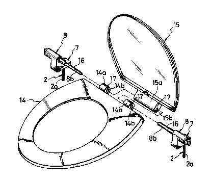
For fitting a toilet seat 14 and a toilet lid 15 to a
toilet pan 3 as shown in Fig. 7, the fitting rod 2 is
fitted into the fitting hole 3 of the toilet pan 3 and
then the receiving member 1 is rigidly fitted to its
proper position of said toilet pan 3 as illustrated in
Figs. 4(a) through (d).
Then, the movable shaft 8b of the hinge 8 is fitted
into shaft bearing holes 14b, 15b bored through respective
bosses 14a, 15a of a toilet seat 14 and a toilet lid 15
and locked by means of a key 16 arranged on the movable
shaft and a key receiving groove 17 arranged within the
shaft bearing holes 14b, 15b.
Thereafter, both the toilet seat 14 and the toilet
lid 15 are kept under an rearwardly inclined state as
illustrated in Fig. 4(a) by holdiny by hand the hinge 3
and the main body 7. Thereafter, the spindle 13 of the
main body 7 is fitted into the groove 6 of the receiving
member 1 and then the rear end section of the main body 7
is pressed downward as indicated by arrow P in Fig. 4(b)
so that the lower surfaces of the tripping members 9e, 9e
of the hook 9 abut the respective inclined upper surfaces
5a, 5a of the abutments 5, 5 to rotate the hook 9 clock-
wise as indicated by arrow a against the spring force.
When the main body is pressed down further, the
tripping members 9e, 9e are rotated further in the direc-
,
~ v~ ~J
';
tion as indicated by arrow a as they are guided by therespective inclined surfaces 5a, 5a until they move off
the surfaces 5a, Sa and rotated counterclockwise by the
spring force so that the tripping surfaces 9f, 9f of the
tripping me~bers 9e, 9e and the respective abutting sur-
faces 5b, 5b of the abutments 5, 5 come into engagement as
illustrated in Fig. 4(c) and consequently the toilet seat
14 and the toilet lid 15 are securely fitted to the toilet
pan as the main body 7 is flatly placed on the receiving
member 1.
For removing the toilet seat 14 and the toilet lid 15
from the toilet pan, the hook 9 is lifted upward against
the spring force as indicated by arrow b in Fig. 4(d) and
then rotated counterclockwise to release the engagement of
the abutting surfaces 5b, 5b of the abutments 5, 5 and the
respective tripping surfaces 9f, 9f the tripping members
9e, 9e so that the toilet seat 14 and the toilet lid 15
can be removed by lifting said maln body 7.
Figs. 5(a) and (b) and Figs. 6(a) and (b) illustrates
a second embodiment of the invention. While the main body
7, the hook 9 and the spring 12 of the first embodiment
are realized in so many separate members, the main body 7
and the hook 9 are integrally formed in this second embod-
iment and the base section of said hook 9 is resiliently
formed so that the main body 7 is locked by a receiving
; . ~:.
~ 3
-
member due to the resilience of the hook 9.
More specifically, said main body 7 is made of an
elastic material such as metal and integrally formed with
a hinge case 8a of a hinge 8, said main body having a pair
of parallel and longitudinal slits 18, 18 at its rear end
to form between them a hook 9, which has along its lower
base section a lateral groove 19 to form a thin area 20
just above said groove 19 so that the thin area shows a
certain degree of flexibility and the hook 9 may be bent
upward against the resilience of that area.
Tripping members 9e, 9e similar to the those of the
first embodiment are arranged on the lower surface of said
hook 9.
The axis 0 of relative rotation of receiving member 1
and front base section of the main body 7 is formed by a
ridge 21 which is removably engaged with a groove 22.
Otherwise, this embodiment has a configuration simi-
lar that of the $irst embodiment and its main body 7 is
mounted to and dismounted from the receiving member 1 in a
manner similar to that of the first embodiment.
Reference numeral 23 in Figs. 1, 3, 4(a) through td)
and S(a) and (b) denotes a pair of indents formed on the
lateral sides of the receiving member 1 and reference
numeral 24 denotes a pair of matching projections formed
on the bottom of the main body 7 which are engaged into
14~
said respective indents 23 to block any lateral relative
movement of the receiving member 1 and the main body 7
when the main body 7 is fitted to the receiving member 1.
Now, an embodiment of the fitting device accordin~ to
claim (3) will be described by referring to Figs. 8, 9 and
11. This embodiment has a configuration basically similar
to that of the first and second embodiments described
above, a major difference being in that the current embod-
iment is provided with an additional lever 25, on which a
hook 9 is tripped for its pivotal movement.
More specifically, a pair of threaded fitting rods 2,
2 are projecting downward from a plate-like receiving
member 1 and driven into respective fitting holes 4 of the
ob~ect of fitting 3. A abutment 5 is disposed at the
center of the rear portion of the receiving member 1, said
abutment 5 having an inclined surface 5a, an abutting
surface 5b and a groove 6 formed on its front end as
illustrated in Fig. 11.
Main body 7 is configured substantially similar to
the main body of the first embodiment and may be stably
tightly placed on said receiviny member 1, while it is
equipped with a hinge 8 and comprises a pair of brackets
7~, 7~ symmetrically arranged at the center of the rear
portion of the main body 7 with a certain distance provid-
ed therebetween. In this embodiment, however, not only a
. : - .
,
-
~3 ~ ~js
hook 9 but also a lever 25 are held by a spindle 10 which
is realized in the form of a hollow pin that runs through
spindle bearing bores 7f, 7f of said brackets 7j, 7j in
such a manner that the hook 9 and the lever 25 may be
vertically swingable.
~ Said hook 9 comprises a first tripping member 9e
i extending downward from bearing section 9i with an in-
versely L-shaped cross section and provided with a trip-
ping surface 9f and a second tripping member 9k extending
rearward from said bearing section 9f and provided with a
horizontal tripping surface 9j.
Said haok 9 also comprises a spindle bore 9c and a
spring containing cavity 91 formed by radially enlarging a
part of said spindle bore 9c, a spring 12 being fitted
around said spindle 10 and contained in said spring con-
taining cavity 91 with its one end 12a supported by a
spring holder 9h.formed by notching a portion of said
spring containing cavity 91 and its other end extended out
of a horizontal groove 9m on a portion of the side wall of
said spring containing cavity 91 and supported by another
spring holder 9g arranged on said main body 7 in order to
downwardly bias said hook 9 (clockwise as illustrated in
Fig. 9), said tripping member 9e being removably received
by the abutment 5 of the receiving member 1.
In this embodiment again, the front side 9g of said
16
, . , . . :
~'~ ' -'' ' " ' ' .
- s~j f~ 3 s ~;
tripping member 9e of said hook g preferably have a curved
surface with an appropriate radius of curvature so that it
may smoothly slide on the inclined surfaces 5a of the
abutment 5.
Said spring 12 is locked against coming off by means
of a washer-like lock cap 11 which is rigidly fitted into
the spring containing cavity 91.
The lever 25 swingably fitted to the main body 7 by
means of the spindle 10 is provided with a pair of brack-
ets 25b, 25b having respective spindle bores 25a, 25a and
symmetrically arranged with a certain distance provided
therebetween. A horizontal groove 25c extends between
said brackets 25b, 25b and faces forward, a tripping
section 25e with a horizontal and upwardly facing tripping
surface 25d being formed along the lower edge of said
horizontal groove 25c so that the second tripping member
9k of said hook 9 is received by said tripping member 25e
when said hook 9 is fitted into said groove 25c. Said
hook 9 is upwardly swingable against the spring force of
the spring 12 by means of said lever 25.
Said groove 25c is so sized that the second tripping
member 9k of the hook 9 is vertically swingable without
friction when the main body 7 is fitted to the receiving
member.
The lever 25 has a horizontal upper surface 25f and
17
- ,
G~ ?~
an inwardly curved rear surface 25g so that it has a
substantially triangular side view with finger a grip
formed by said upper surface 25h and said curved rear
surface 25g and extending rear-upward and a rear wall 25i
for covering said hook 9 to blind it.
A spindle 13 is provided at the front area of said
main body 7 and extending from the lateral sides 7d, 7d of
the main body 7 as illustrated in Fig. 11. Said spindle
13 provides an axis of vertical swinging motion of said
main body 7 when said spindle 13 is fitted into the hori-
zontal groove 6 at the front side of said receiving member
1 for removably fitting said main body 7 to the receiving
member 1.
Fig. 11 shows an embodiment of the device according
to claim 4 of the present invention. In this embodiment,
a hook actuating saction 25n is formed by extending a
member that corresponds to the second tripping member 9k
of the first and second embodiments of the hook 9.
On the other hand, main body 7 of this embodiment has
a cover section 7k extending rearward from its rear end.
This cover section 7k shows an inversely U-shaped cross
sectional view formed by its horizontal top wall 71 de-
signed to cover the upper and lateral areas of the hook 9
and a pair of lateral walls 7m, 7m projecting downward
from the lateral edges of said top wall 71 and having a
~J~Q~.'J
rear opening. The hoo~ 9 can be rotated upward against
the spring force of the spring to release the engagement
between its tripping member 9e and the abutment of the
receiving member 1 by holding said top wall 71 and said
, hook actuating section 25n rearwardly extended from the
bearing section 9i with a thumb and a forefinger.
A device according to claim (3) or claim (4) can be
fitted to a toilet pan in a substantially same manner as a
device according to claim (1) or (2) in order to swingably
fit a toilet seat and a toilet lid to the pan.
~; <~Effects of the Invention
As is apparent from the above description, a device
according to claim (1) can be used for removably fitting a
toilet seat and a toilet lid to a toilet pan by simply
bringing the main body and the receiving member into
engagement at their base sections to provide an axis of
rotation, pressing down the front end of said main body
relative to the receiving member around the axis and then
rotating upward the front end of the hook so that the
toilet pan, the toilet seat and the toilet lid can be
serv~ced and maintained without difficulty.
With such a device, both the toilet and the toilet
lid can be easily removed from the toilet pan for clean-
ing. Since the hinge of the device is free from any
screws and protrusions, a toilet pan equipped with such a
,.~,
device can be shipped after assembling it with a toilet
seat and a toilet lid with the receiving member fitted to
the toilet pan. The toilet seat or the toilet lid of the
assembly can replaced without difficulty whenever it is
damaged for some reason.
A device according to claim (2) can be securely
fitted to an object of fitting by simply pressing the
fitting rod of the receiving member without nuts and hence
without requiring any screwing operation.
Since a device according to claim (3) comprises a
hook which is contained within a lever, it offers an
esthetically improved appearance because the hook as well
as the area of engagement of the tripping member of the
hook and the abutment of the receiving member are not
visible from outside. Besides, such an arrangement pro-
vides an improved safety when the main body is fitted to
or removed from the receiving member because it eliminates
any risk of pinched fingers during the fitting or removing
operation. Moreover, the lever provides easy releasing
operations.
As a device according to claim (4) is provided with a
cover extended from the main body to cover the hook and
its axis of rotation as well as the spring, it offers an
even more improved appearance and the cover effectively
protects the axis of rotation of the hook against dust and
f,~
dirt. As the hook can be rotated by holding with hand the
hook actuating section projecting from the hook along with
the cover of the main body, the hook can be operated with
an enhanced easiness.
4. Brief Description of the Drawings
Fig. 1 is an exploded perspective view of an embodi-
ment of the device for fitting a toilet seat and a toilet
lid according to claim (1) and claim (2).
Fig. 2 is an enlarged sectional side view of the
embodiment of Fig. 1, showing a portion thereof when it is
locked.
Fig. 3 is an enlarged sectional side view of the
embodiment of Fig. 2, showing a portion thereof when it is
unlocked.
Figs. 4(a), (b), (c) and td) are sectional side views
of the embodiment Fig. 1, showing in sequence how it is
released from a locked condition.
Fig. 5 is an exploded perspective view of a second
embodiment.
Figs. 6(a) and (b) are sectional side views of the
embodiment of Fig. 5 under a locked condltion.
Fig. 7 is an exploded perspective view of the embodi-
ment of Fig. 5, showing how it is used to fit a toilet
seat and a toilet lid.
Fig. 8 is an exploded perspective view of an embodi-
21
'
jment of the device according to claim (3).
~`~Fig. 9 is a sectional side view of the embodiment of
$ Fig. 8.
.~ Fig. 10 is a sectional side view of an embodiment of
the device according to claim (4).
Fig. 11 is a partial sectional view of the embodiment
^~ of Fig. 10, showing the axis of rotation of its main body
around the seceiving member arranged at its front end.
22
~ . ; .
~'
~ ' ' ' '' '~ - ' ' ' .
~ '
, ~3 ~
l...receiving member, 2...fitting rod, 2a...screw,
3...object of fitting, 4...fitting hole, 5...abutment,
5a...inclined surface, 5b...abutting surface, 6...
groove, 7...main body, 7a...top wall, 7b...rear wall,
7c...front wall, 7d...side wall, 7e...notch, 7f...
spindle bearing hole, 7g...spring receiver, 7h...bottom
surface, 7i...spindle bore, 7j...bracket, 7k...cover
section, 71...top wall of the cover section, 7m...side
wall of the cover section, 8...hinge, 8a...case,
8b...movable shaft, 9...hook, 9a...upper surface,
9b...10wer surface, 9c...spindle bore, 9d...engaging
surface, 9e...tripping member, 9f...tripping surface,
9g...10wer front side, 9i...bearing section, 9j...trip-
ping surface, 9k...tripping member, 91...spring contain-
ing cavity, 9m...groove, 9n...hook actuating section,
lO...spindle, ll...hook cap, 12...spring, 12a...an end
of the spring, 12b...the other end of the spring,
13...spindle, 14....toilet seat, 14a...boss, 15...
toilet lid, 15a...boss, 16...key, 17...key groove,
18...slit, l9...groove, 20...thin area, 21...ridge,
22...groove, 23...indent, 24... projection, 25...lever,
25a...spindle bore, 25b... bracket, 25c...groove,
25d...tripping surface, 25e... tripping member,
25f...upper surface, 25g...curved surface, 25h...finger
grip, 25i...rear wall, O...axis of rotation~
., .