Note : Les descriptions sont présentées dans la langue officielle dans laquelle elles ont été soumises.
3 ~ 7 ~
GUIDE OR FEEDER CHAIN FOR POWER AND SUPPLY LINES
sackground of the Invention
The present invention relates to a guide or
:.~
feeder chain for power and supply lines, and
- includes chain links that comprise two spaced-apart
~` link members that are disposed parallel to one
- another and are interconnected by crosspieces, with
the chain links having a reciprocal pivot angle
~; that is delimited by abutment inserts, with exposed
sides of the chain links being covered by cover
.
plates that are secured to the crosspieces, and -
with end links of the chain being connected, via
brackets or connectors, on the one hand to a fixed -~
connection and on the other hand to a movable
consuming device.
DE-PS 23 60 227 discloses a guide or feeder ~;
. .; . .
chain where the reciprocal pivot angle of the chain
links is delimited by abutment inserts that are
loosely disposed in slots that are curved about the
pivot axis. A drawback of this pivot angle
delimitation, which actually functions ~uite well,
is that during assembly the abutment inserts can be
:-
-! interchanged, and after assembly it is no longer
possible to determine if the correct abutment
inserts are disposed in all of the slots.
DE-PS 22 55 283 discloses a guide or feeder
~ ' :':~
, . ' .
. :.
. ,: i... :. .-., ::.: . : - ::
~23~75
.
chain where the link members are connected by
crosspieces that have a flattened cross-sectional
configuratlon with rounded narrow sides, with the
crosspieces being dlsposed in recesses of the link
members or of separators, which recesses are
provided with undercuts, whereupon the crosspleces
are rotated about their longitudinal axis to secure
them in a frictional and interlocking manner with
the link members or separators. Although these
separators have proven themselves in practice, for
guide or feeder chains that have a great length and
carrying weight, the stability of the crosspieces
:j - .
is not always adequate.
, DE-PS 24 17 353 discloses a guide or feeder
chain where the chain links are connected with
crosspieces in which are disposed elastically
deformable clamping lips of soft plastic between
which the power and supply lines can be clamped.
Unfortunately, thls technology for fixing the
~ .
position of power and supply lines that have
different diameters can function well for only a
certain range of differing diameters. This known
clamping lip construction is not very suitable for
extremely large or small diameters.
EP-OS O 2460502 discloses a guide or feeder
chain that is covered at the upper and lower sides
:
2397~
. .
:`
by cover plates that are secured to the
.. .
crosspieces. With one embodiment, the ends of the
curved cover elements, which are disposed in the
region of the pivot axis and span the gap between
the cover plates of ad~acent chain links, are
guided in recesses of the link members. In another
embodiment, the curved cover elements are
integrally formed on one side of the cover plates,
which are connected to the crosspieces. The first
embodiment requires a corresponding construction of
the link members, and with the second embodiment,
the area between the cover plates and the cover
elements is vulnerable to breaking.
Starting from these known constructions, it is
,: ~
,1 an obJect of the present invention to provide a
guide or feeder chain that can be assembled from
~ various prefabricated parts so as to have various
.':;
~ crosspieces, radii of curvature, stems, covers, and
`~ connectors for the purpose of being able to adapt
to various applications.
Brief Description of the Drawings
This ob~ect, and other objects and advantages
of the present invention, will appear more clearly
from the following specification in con~unction
` with the accompanying schematic drawings, in which:
Fig. 1 is a partially exploded view
- 3 -
~
of one exemplary embodiment of
an lnventive chaln link having
an asymmetrically wldened
crosspiece;
I Fig. 2 is an exploded view showing
;~ two ad~acent link members
. ~
between which are disposed
~- abutment inserts that have
,`:1 : .
been connected into a ring:
Fig. 3 shows two abutment inserts
that are connected by a stem;
Fig. 4 is a partially exploded view
showing two end links and
~: -
associated connectors,
Fig. 5 is a side view of an end link;
Fig. 6 is a partially exploded view
of a chain link where brushes
a r e s e c u r e d i n t h e
crosspieces~
Fig. 7 i8 a partially exploded view
of a chain link in which cover
plates are secured on the
crosspieces; and
Fig. 8 is a cross-sectlonal view
taken along the line VIII-VIII
in Fig. 7.
- 4 ~
~ ' ' '
g7 ~i
25476-150
Summary o~ the Invention
: The present invention provides in a guide or feeder chain
~; for power and supply lines, including chain links that comprlse
; two spaced-apart link members that are disposed parallel to one
- another and are interconnected by crosspieces, with said chain
,7 links having a reciprocal pivot angle that is delimited by ~ -
'! abutment inserts, with exposed sides of said chain links being
covered by cover plates that are secured to said crosspieces, and
. with end links of said chain being connected, via connectors, on :~
-~ lO the one hand to a fixed connection and on the other hand to a ~ :
movable consuming device, the improvement wherein: at least some
. of said crosspieces, along a portion thereof disposed between said
link members, have an enlarged cross-sectional configuration;
each of said abutment inserts is interconnected to at least one
~ other abutment insert via stem means that fixedly extends into
~ corresponding notch means of said link members; a respective ~:
curved cover element is telescopically guided on one side of each
of said cover plates, with each cover element aovering the region
of a link pivot axis and extending below an adjacent cover plate;
and each of said end links has two ends, one of which is embodied ~
to connect to one of said link members, and the other of which is :
provided with a pocket to receive variously shaped ones of said
connectors.
: Pursuant to one practical specific embodiment of the
present invention, the crosspieces can have an asymmetrically
widened proflle between the chain link, or can also have a
symmetrical configuration and can be provided on their inner side
: with a T-shaped groove for securing a brush, with the ends thereof ::
-5-
25476-150
i, .~
. facing one another on both sides of the neutral plane of a chain
link. In the first variation, the crosspieces increase the
stability
3 .
~, .
~` ~
f~
, . . .:
."~' ~ '.
,: :
., .
.' . ' ~
.', ' ' ,~,
'',:`' ~ ~
.~
r
} -5a-
'
2~ 2~
,
.;.
of the chain links. In the second varlation, the
crosspieces not only lncrease the stability of the
chain links, but they also permit the use of
brushes, so that power and supply lines having
extremely different diameters can be accommodated
and can be kept separate from one another during
operation of the guide or feeder chain.
The connection of the abutment lnserts via
stems to form an abutment ring, and also the
connection of at least two abutment inserts for ~
ad~acent slots via a stem, has the advantage that ;-
the abutment inserts can no longer be interchanged,
because they now fit only in the same position vla
their stem, in the corresponding notches between
the slots of the link members. As a further
lmprovement, lt is proposed that the abutment ;
lnserts addltionally be provided with round heads,
and that round holes be provlded in the link
members in the region of the slots thereof, with
the round heads of the abutment inserts then
extending into these round holes so that when
assembly of the guide or feeder chain is completed,
these round heads are visible from the out ide. On
their visible side, the round heads can be provided
with lettering or can also be marked in color to
designate various radii of curvature. In this way,
..: ~
- 6 -
~ ~23~75
after assembly it is immediately recognlzable in
which plvot connection abutment inserts are mlssing
or where the wrong abutment inserts have been used. ~ -~
Pursuant to a further specific embodiment of
the present invention, it i8 proposed that on one
longitudinal side the cover plates have two halves
and be provided with a slot for accommodating a
curved cover element. The curved cover elements
can then be inserted into the cover plates from the
end. So that the curved covered elements cannot
slide out of the accommodating slot of the cover --
plate, the cover elements are expediently provided
on both longitudinal side3 with stop ridges, one of
which cannot move past the accommodatlng slot of
the cover plate, and with the other extending below
the ad~acent cover plate. So that the curved cover
elements are guided in the accommodating slot of
the cover plates and in contact against the
ad~acent cover plates, profiled support members can
be formed on the inner sides of the link member~
and can extend below the ends of the curved cover
element~.
It i finally proposed to provi~e holes in the
end links in the vicinity of the pockets thereof so
a3 to be able to screw in the insertable
connectors.
.
-
2 3 ~ 7 .~
...j
, .
A guide or feeder chain that is constructed
pursuant to the teaching of the present invention
:;
can be completed in many different ways and can
thus be optimized for specific applications. For
example, it is possible, in place of simple
crosspieces, and in con~unction with the same link
members, to use crosspieces that lncrease the
stability. If it is necessary to be able to guide
power and supply lines having extremely different
diameters and to keep these lines separate from one
another, inwardly proJecting brushes can be
inserted lnto the crosspieces, wlth the bristles of
these brushes extending about the power and supply
lines in a protective manner and keeping them
spaced apart. If the guide or feeder chain has to
be covered or enclosed in order to protect the
power and supply llnes from hot shavings and/or
dust, the cover plate wlth the telescopically
provided cover elements can be placed upon the
crosspieces from the outside. The connection
situations for the end links, which change from
case to case, can be established with variously
shaped connectors, one end of each of which has an
lnsertion end that fits into a pocket of an end
llnk.
Further speclflc features of the present
- 8 -
: - `, ` ' ~ . , : ~ ` ' . . .
:..`.
invention will be described in detail subsequently.
Description of Preferred Embodiments
, ~ ,, .
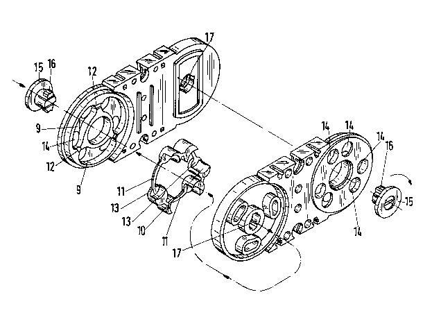
Referring now to the drawings in detail,
various of the figures show a chain link comprised
of two spaced-apart link members 1 and 2 that are
dispo~ed parallel to one another and are
interconnected via crosspleces 3 and 4. Along
their entire length, the crosspieces 3 have a
flattened cross-sectional configuration with
rounded narrow sides and can be placed into cut-
into or gated recesses 5 in the narrow sldes of the
link members. The recesses 5 are provided with
undercuts, and the crosspieces 3 can, after being
placed in the recesses 5, be twisted about their
longitudinal axis in order to frictionally and
interlockingly connect them to the link members 1,
2. The other crosspiece 4, along a length that
corresponds to the distance between the two link
members, has an asymmetrical cross-sectional
conflguration in order to increase the stability of
the guide or feeder chain. So that the crosspiece
4 cannot be unintentionally loosened, holes 6 are
provided into which screws that extend through
holes 7 of the loop members 1, 2 can be inserted.
The reciprocal pivot angle of ad;acent chain
llnks is delimited by abutment cams 8 that engage
_ g _ '
`5 ~ ~
23975
.. .
in curved cutouts 9 of an ad~acent link member.
The abutment cams 8 and cutouts 9 formed on a link
~, ,
member 1, 2 define a specific, maximum plvot angle
that results in a specific radius of curvature for
the guide or feeder chain. To reduce the pivot
angle and enlarge the radius of curvature, abutment
inserts 10 can be placed into the cutouts 9. In
the embodiment illustrated in Fig. 2, these
abutment inserts 10 are connected together by stems
11 to form a ring. However, as shown in the
embodiment of Fig. 3, the abutment lnserts 10 can
also be connected in pairs by s~ngle stems 11 in
order to preclude mistakes. NotcheQ 12 that
.
correspond with the stems 11 are provided for the
abutment inserts 10 in the link members 1, 2
between the cutouts 9.
The abutment inserts 10 are provided with
rounded heads 13 that extend into correspondingly
shaped round holes 14 in the cutouts 9 and are
visible from the outside.
i.
Two chain links are held together via locking
pins 15 that can be inserted along the pivot axis -
and that can catch in pivot holes I7 at one end of
` the link members 1, 2 via resilient disposed
locking cams 16.
~'3 The first and last cha~n link of a guide or
., _ 10
~,
~` ~
i7 ~
. ~
feeder chain comprises two end links 18, 19 that
are cut off at one end and are provided with a
pocket 20 into which can be inserted a connector 21
having an appropriate insertion end 22, whereupon
the connector 21 can be secured via a screw 23.
The connectors 21 can have differently shaped
connection ends 24 that are adapted to the
respective conditions (see for example the dot-dach
line representation of one alternative in Fig. 4).
As illustrated in Fig. 6, in place of the
crosspieces 3, 4 of Fig. 1, it is also possible to
use wider crosspieces 25 that are provided on the
lnner side with a T-shaped groove 26 into which is
inserted a bracket 27 for a brush 28. The two
crosspieces 25 are secured to the link members 1, 2
by screws 29. The two inwardly proJecting brushes
28 end on elther side of the neutral plane of the
chain llnks and can in a protective manner securely
hold in place power and supply lines that have
extremely different dismeters, and can keep these
lines separate from one another.
In the embodiment illustrated in Figs. 7 and
8, separators 30 having dividers 31 are disposed
between the crosspieces 3. In addition, cover
plates 32 are secured upon the crosspieces 3.
Along one longitudinal side, these cover plates 32
:
-- 11 --
,:
: ``
2 ~ ~ 7 ~
' :
have two halves and form a receivlng slot for a
curved cover element 34. The two ends of the
curved cover elements 34 are provlded wlth stop
. ~
rldges 35 that on the one hand cannot 81ip out of
the receivlng slot 33, and at the othar side extend
below the ad~acent cover plate 32. The ends of the
cover elements 34 rest against profiled support
members 36 that are formed on the link members 1
and 2.
In the covered guide or feeder chaln
illustrated in Figs. 7 and 8, sliding skids 37 are
placed upon the narrow sides of the link members 1
and 2. These sliding skids 37 are provided with an
inwardly dlrected tab 38 to hold the cover plates
32 down.
The present invention is, of course, in no way
restricted to the ~pecific discloRure of the
specification and drawings, but also encompasses
any modifications within the scope of the appended
clalms.
~ '
- 12 ~