Sélection de la langue

Search

Sommaire du brevet 2024400 

Énoncé de désistement de responsabilité concernant l'information provenant de tiers

Une partie des informations de ce site Web a été fournie par des sources externes. Le gouvernement du Canada n'assume aucune responsabilité concernant la précision, l'actualité ou la fiabilité des informations fournies par les sources externes. Les utilisateurs qui désirent employer cette information devraient consulter directement la source des informations. Le contenu fourni par les sources externes n'est pas assujetti aux exigences sur les langues officielles, la protection des renseignements personnels et l'accessibilité.

Disponibilité de l'Abrégé et des Revendications

L'apparition de différences dans le texte et l'image des Revendications et de l'Abrégé dépend du moment auquel le document est publié. Les textes des Revendications et de l'Abrégé sont affichés :

  • lorsque la demande peut être examinée par le public;
  • lorsque le brevet est émis (délivrance).
(12) Brevet: (11) CA 2024400
(54) Titre français: MECANISME DE BLOCAGE ET DE SERRAGE POUR CEINTURE DE SECURITE
(54) Titre anglais: BELT LOCK FOR A SAFETY BELT SYSTEM PROVIDED WITH A TIGHTENING MEANS
Statut: Périmé et au-delà du délai pour l’annulation
Données bibliographiques
(51) Classification internationale des brevets (CIB):
  • B60R 22/18 (2006.01)
  • A44B 11/25 (2006.01)
  • B60R 22/195 (2006.01)
(72) Inventeurs :
  • FOHL, ARTUR (Allemagne)
(73) Titulaires :
  • TRW REPA GMBH
(71) Demandeurs :
  • TRW REPA GMBH (Allemagne)
(74) Agent: SMART & BIGGAR LP
(74) Co-agent:
(45) Délivré: 1994-12-20
(22) Date de dépôt: 1990-08-31
(41) Mise à la disponibilité du public: 1991-03-02
Requête d'examen: 1990-11-15
Licence disponible: S.O.
Cédé au domaine public: S.O.
(25) Langue des documents déposés: Anglais

Traité de coopération en matière de brevets (PCT): Non

(30) Données de priorité de la demande:
Numéro de la demande Pays / territoire Date
P 39 29 114.6 (Allemagne) 1989-09-01

Abrégés

Abrégé anglais


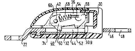
A belt lock for a safety belt system provided with a
tightening means operative between the belt lock and an
anchoring point on the vehicle body is provided with a
compensation mass which is deflected by a two-armed lever
and compensates the inertial forces of the release button
and the parts connected thereto.

Revendications

Note : Les revendications sont présentées dans la langue officielle dans laquelle elles ont été soumises.


C 1 a i m s
1. In a vehicle having a bodywork and seats, a safety belt
system comprising:
- a belt fitting having an insert tongue,
- a belt lock,
- an anchoring means for attachment to one of the vehicle
bodywork and vehicle seat, and
- a tightening means operative between the belt lock and the
anchoring means,
the belt lock comprising:
- a housing provided with a guide path for the insert
tongue,
- a detent opening in the insert tongue,
- a latch mounted in the housing and displaceably guided
therein in a direction transverse to the guide path be-
tween a holding position in which the latch engages the
detent opening of the insert tongue and a release position
in which the latch is disengaged from said detent opening,

- a blocking member mounted in the housing and displaceably guided
in parallel to the guide path between a holding position in which
the blocking member maintains said latch in its holding position
and a release position in which the blocking member disengages
said latch to allow the latter to move to its release position,
- a manually operable release button mounted in the housing and
likewise displaceably guided therein in parallel to the guide
path, said release button being coupled to said blocking member to
move the latter to its release position, whereby the latch is also
moved to its release position out of engagement from the detent
opening of the insert tongue,
- a two-armed lever pivotally mounted on said housing about a pin
perpendicular to said guide path, said lever having a first arm
mounting a compensation mass within the housing and a second arm
in force-transmitting engagement with one of the release button
and the blocking member, the arrangement being such that said
compensation mass, upon acceleration and deceleration of said
belt lock in the direction of said guide path develops inertial
forces transmitted to one of said release button and said blocking
member by said two-armed lever in a direction opposite to inertial
forces developed by said release button or blocking member in
response to the same acceleration and deceleration.
2. The improvement as set forth in claim 1, wherein:
- said compensation mass is formed by a bent portion of said first
arm of the two-armed lever,
- the second arm of the two-armed lever has a bent portion, bent
in opposite direction to the bent portion of said first arm,

10a
forming a crank lug,
- said one of the release button and the blocking member is
provided with a recess, and
- said crank lug engages said recess.

11
3. The improvement as set forth in claim 1, wherein said
housing comprises a load-bearing member, said load-bearing member
being provided with a lateral extension adjacent said guide path,
and said two-armed lever being pivotally mounted onto said
lateral extension.
4. The improvement as set forth in claim 2, wherein said
recess is disposed at an edge of the blocking member parallel to
the guide path.
5. The improvement as set forth in any one of claims 1
to 4, wherein the blocking member is a plate connected in form-
locking manner to the release button.
6. The improvement as set forth in any one of claims 1
to 4, wherein said housing comprises a load-bearing member, and
said latch is a pivot latch mounted on the load-bearing member
of the lock housing.
7. In a vehicle having a bodywork and seats, a safety belt
system comprising:
- a belt fitting having an insert tongue,
- a belt lock,
- an anchoring means for attachment to one of the vehicle body-
work and vehicle seat, and
- a tightening means operative between the belt lock and the
anchoring means,
the belt lock comprising:

12
- a housing provided with a guide path for the insert
tongue,
- a detent opening in the insert tongue,
- a latch mounted in the housing and displaceably guided
therein in a direction transverse to the guide path be-
tween a holding position in which the latch engages the
detent opening of the insert tongue and a release position
in which the latch is disengaged from said detent opening,
- a blocking member mounted in the housing and displaceably
guided in parallel to the guide path between a holding
position in which the blocking member maintains said latch
in its holding position and a release position in which
the blocking member disengages said latch to allow the
latter to move to its release position,
- a manually operable release button mounted in the housing
and likewise displaceably guided therein in parallel to
the guide path, said release button being coupled to said
blocking member to move the latter to its release posi-
tion, whereby the latch is also moved to its release posi-
tion out of engagement from the detent opening of the in-
sert tongue,
- a two-armed lever pivotally mounted on said housing about
a pin perpendicular to said guide path, said lever having
a first arm mounting a compensation mass and a second arm
in force-transmitting engagement with one of the release
button and the blocking member,
the improvement wherein:
- said housing comprises a load-bearing member,

13
- said two-armed lever is pivotally mounted onto said load-
bearing member opposite to the blocking member, and
- said compensation mass is articulately connected within the
housing to the first arm of the two armed lever and said
compensation mass is formed by a bent portion of said first arm
of the two-armed lever.
8. The improvement as set forth in claim 7, wherein said
compensation mass is formed as an elongated plate and is
displaceably mounted in said lock housing in parallel to said
guide path.
9. The improvement as set forth in any one of claims 1
to 4, 7 or 8, wherein the tightening means is constructed as a
piston and cylinder linear drive having a pyrotechnical gas
generator for subjecting the piston to pressurized gas in the
event of actuation of said pyrotechnical gas generator.
10. The improvement as set forth in claim 9, wherein the
piston of the piston and cylinder linear drive is connected to
said belt lock via a pulling cable, and said belt lock is
displaceably guided in an elongated guide by means of a fitting.
11. The improvement as set forth in claim 10, wherein said
pulling cable is deflected between the belt lock and the piston
and cylinder linear drive.

Description

Note : Les descriptions sont présentées dans la langue officielle dans laquelle elles ont été soumises.


~02440~
Belt lock for a safety belt system
provided with a tightening means
The invention relates to a belt lock.
Belt locks for safety belt systems are known in numerous
constructions. A constructional form has proved itself in
which in the housing of the belt lock a guide path for the
insert tongue is formed and a latch displaceably guided on
the housing transversely of the guide path or pivotally
mounted thereon cooperates with a detent opening of the
insert tongue. A blocking member displaceably guided para-
llel to the guide path in the housing holds the latch in its
locking position as long as a release button likewise guided
displaceably parallel to the guide path in the housing is
in its rest position. The release button is coupled to the
blocking member for moving the latter on actuation into a
release position in which the latch comes free of the detent
opening of the insert tongue.

2 2024400
- 28075-4
The use of such a belt lock in safety belt systems
having a tightening means does not involve any problems when
the tightening force acts for example at the belt retractor.
Tightening means have also already been proposed which are
operative between the belt lock and its mounting point on the
vehicle bodywork or a vehicle seat. Such tightening means
shorten the distance between the securing point of the belt lock
and the lock itself by a few centimetres, for example 10 cm.
The tightening means used in such cases are mechanically
constructed and have a force accumulator in the form of a
tensioned spring which is released by a sensor responsive to
inertial forces and effects a tightening when required.
To make available the necessary tightening force
mechanical tightening means require a very strongly dimensioned
spring. The vehicle-sensitive release of such a spring at
satisfactorily reproduceable release thresholds presents great
difficulties.
With a pyrotechnical tightening means comprising as
tightening drive a piston/cylinder linear drive having a pyro-
technical gas generator subjecting the piston in the cylinderto pressurized gas when released high tightening forces can be
obtained relatively easily. It has however been found that a
belt lock of the type mentioned at the beginning tends to open
automatically when used in conjunction with such a pyrotechnical
tightening means.
The present invention provides in a vehicle having a
bodywork and seats, a safety belt system comprising: a belt
fitting having an insert tongue, a belt lock, an anchoring means

202~400
3 28075-4
for attachment to one of the vehicle bodywork and vehicle seat,
and a tightening means operative between the belt lock and the
anchoring means, the belt lock comprising: a housing provided
with a guide path for the insert tongue, a detent opening in the
insert tongue, a latch mounted in the housing and displaceably
guided therein in a direction transverse to the guide path between
a holding position in which the latch engages the detent opening
of the insert tongue and a release position in which the latch is
disengaged from said detent opening, a blocking member mounted in
the housing and displaceably guided in parallel to the guide path
between a holding position in which the blocking member maintains
said latch in its holding position and a release position in which
the blocking member disengages said latch to allow the latter to
move to its release position, a manually operable release button
mounted in the housing and likewise displaceably guided therein in
parallel to the guide path, said release button being coupled to
said blocking member to move the latter to its release position,
whereby the latch is also moved to its release position out of
engagement from the detent opening of the insert tongue, a two-
armed lever pivotally mounted on said housing about a pinperpendicular to said guide path, said lever having a first arm
mounting a compensation mass within the housing and a second arm
in force-transmitting engagement with one of the release button
and the blocking member, the arrangement being such that said
compensation mass, upon acceleration and deceleration of said
belt lock in the direction of said guide path develops inertial
forces transmitted to one of said release button and said blocking
member by said two-armed lever in a direction opposite to inertial
~'

202~00
3a 28075-4
forces developed by said release button or blocking member in
response to the same acceleration and deceleration.
This belt lock can be used without problems in safety
belt systems which are equipped with tightening means generating
relatively high tightening forces. The compensating mass balances
the mass of the release button and all the parts connected
thereto. In the event of tightening, the belt lock is moved by
the tightening force with extremely high acceleration towards its
securing point on the vehicle bodywork or on a vehicle seat. At
the end of the tightening travel the belt lock and its securing
fitting reach a high velocity, as do the release button of the
belt lock and all masses coupled thereto. The travel of the
tightening movement is limited for practical reasons so that the
securing fitting of the belt lock can strike a stop limiting the
tightening travel with high velocity. Due to the mass inertial
forces the release button with the masses coupled thereto tends to
continue its movement, i.e. a movement in a direction which
corresponds to the normal actuation of the release button for
opening the belt lock. Under unfavourable circumstances, in this
process an automatic opening of the belt lock may occur. With the
step according to the invention such an automatic opening is
however reliably prevented because the inertial forces of the
release button and the masses coupled thereto are opposed by a
compensating force which is generated by the mass inertia of the
compensation mass.
In practical embodiments of the invention the
compensation mass is dimensioned so that the inertial forces
generated thereby are somewhat greater than those of the release
r:

2D2~400
3b 28075-4
button and the masses coupled thereto. With this step a high
functional reliability is achieved which takes account of
production tolerances, friction and age-dependent changes

-- ~02~
1 and thus prevents an unintentional opening of the belt lock
even in the event of a particularly unfavourable constel-
lation of tolerances and outer influences. The compensation
mass thus generates in the normal case a counter force to
the inertial forces occurring at the release button which is
somewhat greater than these inertial forces.
Advantageous further developments of the invention are set
forth in the subsidiary claims.
Further features and advantages of the invention will be
apparent from the following description of some embodiments
of the invention and from the drawings to which reference
is made and wherein:
Fig. 1 is a schematic perspective view of a tightening means
engagins a belt loc's;
Fig. 2 is a partially sectioned side view of the tighten- ing means;
Fig. 3 is a longitudinal section of a belt lock accord-
ing to the invention in the state when the release
button is actuated;
a5
Fig. 4 is an analogous side view of the belt lock in
the state when the insert tongue is inserted and
locked;
Fig. 5 is a sectional view of the belt lock along the
line V-V of Fig. 4;
Fig. 6 is a cross-section of the belt lock along the
line VI-VI of Fig. 5;
Fig. 7 is a schematic ~erspective view of ~ne functional parts of
the belt lock and

Z02~4~
s
I Figs. 8, 9 and 10 show another embodiment of the belt lock.
The tightening means shown in Fig. 1 consists of a pyro-
technical piston/cylinder tightening drive 10, the cylinder
of which is anchored to the vehicle bodywork, and a longi-
tudinal guide for the belt lock 12 in the form of an elon-
gated anchoring plate 16 provided with a slot 14, a pulling
cable 18 which connects the piston 20 to the securing fitt-
ing 22 of the belt lock and a guide pulley 24 via which the
lC pulling cable 18 is led and which is mounted on a securing
bolt 26 by means of which the anchoring plate 16 is mounted
on the vehicle bodywork.
Figures 1 and 2 show the tightening means in the unactivated
state. As apparent from Fig. 2 the end side of the piston
20 can be subjected to pressurized gases generated by a
pyrotechnical gas generator 28. Under the action of the
pressurized gases the piston 20 is driven with an extremely
high acceleration and via the pulling cable 18 and the secur-
2C ing fitting 22 pulls the belt lock 12 downwardly. At thelower end of the slot 14 the movement of the belt lock 12
is abruptly retarded. By a ratchet mechanism integrated
into the piston 20 the belt lock 12 is prevented from moving
in the direction of its starting position after tightening
a 5 has taken place.
When the belt lock 12 is abruptly retarded at the end of the
tightening stroke, at the release button 30 and the parts
connected thereto high inertial forces occur which are
directed in the direction of the release movement of the
release button. The construction of the belt lock which
will now be described with reference to Figures 3 to 10
prevents these inertial forces leading to unintentional
opening of the belt lock.

6 ~OZ~4Q~
1 The anchoring fitting 22 is connected by a rivet connection
to the loadbearing part of the lock housing 32. Said hous-
ing 32 is surrounded by a cover in the form of a plastic
dish 34. The lock housing 32 is provided with a bearing
bracket which is drawn up in U-shape in plan view and
between the two parallel legs 36, 38 of which a pivot latch
40 is mounted by means of a bearing pin 42. The release
button 30 comprises two parallel arms 30A, 30B which extend
into the lock interior and are provided at their free end
with a guide slot through which the outer ends of the bear-
ing pin 42 engage. The release button30 is slidingly guidedat the outer sides of the legs 36, 38.
The lock housing 32 is provided with a guide path 44 for an
insert tongue 46 which comprises a detent opening 48. A
control cam 50 of the pivot latch 40 projects into the guide
path 44. The pivot latch 40 is further provided with a
detent nose 52 in the region of its free end.
Between the two arms 30A, 30B of the release button 30 a
blocking member 54 in the form of a steel plate is mounted
above a lug 56 at the free end of the pivot latch 40. A
pressure spring 58 bears with its one end on the blocking
member 54 and its other end on a lever arm 60 of the pivot
as latch 40 which lies opposite the control cam 50.
In the position shown in Fig. 3 the lug 56 of the pivot
latch 40 engages behind the front edge of the blocking
member 54 so that the detent nose 52 is pivoted out of the
guide path 44 by the pressure spring 58. The release button
30 is shown in its actuated position.
In the state shown in Fig. 4 the insert tongue 46 is inserted
and the detent nose 52 is locked in the detent opening 48.

7 ~0244(~
1 An extension 62 (Figs. 5, 6 and 7) is laterally mounted on
the lock housing 32. A two-armed lever 66 is pivotally
mounted on said extension 62 by means of a bearing pin 64.
A compensation mass 68 is secured to the one arm of said
lever 66. The other arm of the lever 66 engages by means
of a crank lug 70 in a recess 72 of the blocking member 54.
The compensation mass 68 is thus connected in force-transmitting
manner to the release button 30 and the blocking member 54.
Since the compensation mass 68 is however located at the
arm of the lever 66 remote from the release button 30 and
the blocking member 54 the inertial forces generated by the
compensation mass 68 act opposite to those caused by the
release button 30, the blocking member 54 and all the masses
coupled thereto.
The compensation mass 68 is so dimensioned that under all
circumstances it prevents an opening of the belt lock due
to inertial forces. Preferably, it is dimensioned some-
what greater than the sum of the masses of the release
button 30, the blocking member 54 and all parts connected
thereto.Fig. 8 shows a second embodiment of the belt lock according
to the invention in exploded view; Fig. 9 shows said embodi-
ment in cross-section and Fig. 10 illustrates the relative
a5 arrangement of the release button, the two-armed lever and
the compensation mass.
This second embodiment differs from the previously described
embodiment only in the arrangement and mounting of the two-
armed lever 66 and the compensation mass 68. The two-armed
lever is pivotally mounted in its centre on a bearing pin 80
which is secured in the centre of a plate 82 which connects
the two legs 36, 38 of the lock housing 32 together at their
upper edge. Said plate 82 lies opposite the blocking member
54. The compensation mass 68 is formed as elongated plate

8 ;~ 4~
1 and articulately connected to a crankpin 84 at the end of
the one lever arm of the two-armed lever 66. The compen-
sation mass 68 extends parallel to the longitudinal direction
of the lock housing 32 and is mounted longitudinally dis-
S placeably on said housing.
As apparent from Fig. 10 in this embodiment as well the
two-armed lever 66 effects a reversal of the direction in
which the mass inertial forces due to the compensation mass
68 are operative. The masses of the release button 30 and
all the parts connected thereto are therefore compensated
by the compensation mass 68.
The embodiment according to Figures 8, 9 and 10 permits
easy accommodation of the compensation mass in a lock housing.
as

Dessin représentatif
Une figure unique qui représente un dessin illustrant l'invention.
États administratifs

2024-08-01 : Dans le cadre de la transition vers les Brevets de nouvelle génération (BNG), la base de données sur les brevets canadiens (BDBC) contient désormais un Historique d'événement plus détaillé, qui reproduit le Journal des événements de notre nouvelle solution interne.

Veuillez noter que les événements débutant par « Inactive : » se réfèrent à des événements qui ne sont plus utilisés dans notre nouvelle solution interne.

Pour une meilleure compréhension de l'état de la demande ou brevet qui figure sur cette page, la rubrique Mise en garde , et les descriptions de Brevet , Historique d'événement , Taxes périodiques et Historique des paiements devraient être consultées.

Historique d'événement

Description Date
Inactive : CIB de MCD 2006-03-11
Le délai pour l'annulation est expiré 1999-08-31
Lettre envoyée 1998-08-31
Accordé par délivrance 1994-12-20
Demande publiée (accessible au public) 1991-03-02
Toutes les exigences pour l'examen - jugée conforme 1990-11-15
Exigences pour une requête d'examen - jugée conforme 1990-11-15

Historique d'abandonnement

Il n'y a pas d'historique d'abandonnement

Historique des taxes

Type de taxes Anniversaire Échéance Date payée
TM (brevet, 7e anniv.) - générale 1997-09-02 1997-07-17
Titulaires au dossier

Les titulaires actuels et antérieures au dossier sont affichés en ordre alphabétique.

Titulaires actuels au dossier
TRW REPA GMBH
Titulaires antérieures au dossier
ARTUR FOHL
Les propriétaires antérieurs qui ne figurent pas dans la liste des « Propriétaires au dossier » apparaîtront dans d'autres documents au dossier.
Documents

Pour visionner les fichiers sélectionnés, entrer le code reCAPTCHA :


Pour visualiser une image, cliquer sur un lien dans la colonne description du document. Pour télécharger l'image (les images), cliquer l'une ou plusieurs cases à cocher dans la première colonne et ensuite cliquer sur le bouton "Télécharger sélection en format PDF (archive Zip)" ou le bouton "Télécharger sélection (en un fichier PDF fusionné)".

Liste des documents de brevet publiés et non publiés sur la BDBC .

Si vous avez des difficultés à accéder au contenu, veuillez communiquer avec le Centre de services à la clientèle au 1-866-997-1936, ou envoyer un courriel au Centre de service à la clientèle de l'OPIC.


Description du
Document 
Date
(aaaa-mm-jj) 
Nombre de pages   Taille de l'image (Ko) 
Abrégé 1994-12-19 1 9
Description 1994-12-19 10 331
Revendications 1994-12-19 6 156
Dessins 1994-12-19 4 133
Abrégé 1994-12-19 1 9
Abrégé 1994-02-28 1 8
Description 1994-02-28 8 241
Dessins 1994-02-28 4 125
Revendications 1994-02-28 5 115
Dessin représentatif 1998-07-13 1 10
Avis concernant la taxe de maintien 1998-09-27 1 178
Taxes 1996-07-08 1 41
Taxes 1995-10-16 2 49
Taxes 1994-07-06 1 45
Taxes 1993-08-05 1 26
Taxes 1992-05-12 1 24
Courtoisie - Lettre du bureau 1991-04-23 1 23
Demande de l'examinateur 1990-11-22 1 36
Correspondance reliée au PCT 1994-09-27 1 33
Correspondance de la poursuite 1990-11-14 1 28
Correspondance de la poursuite 1994-03-24 1 30
Demande de l'examinateur 1993-11-25 1 60
Correspondance de la poursuite 1993-05-04 3 82
Demande de l'examinateur 1992-12-09 1 59
Correspondance de la poursuite 1994-04-26 2 44