Sélection de la langue

Search

Sommaire du brevet 2024764 

Énoncé de désistement de responsabilité concernant l'information provenant de tiers

Une partie des informations de ce site Web a été fournie par des sources externes. Le gouvernement du Canada n'assume aucune responsabilité concernant la précision, l'actualité ou la fiabilité des informations fournies par les sources externes. Les utilisateurs qui désirent employer cette information devraient consulter directement la source des informations. Le contenu fourni par les sources externes n'est pas assujetti aux exigences sur les langues officielles, la protection des renseignements personnels et l'accessibilité.

Disponibilité de l'Abrégé et des Revendications

L'apparition de différences dans le texte et l'image des Revendications et de l'Abrégé dépend du moment auquel le document est publié. Les textes des Revendications et de l'Abrégé sont affichés :

  • lorsque la demande peut être examinée par le public;
  • lorsque le brevet est émis (délivrance).
(12) Brevet: (11) CA 2024764
(54) Titre français: ANNEAU DE REMPLISSAGE DE ROBINET DE CHASSE
(54) Titre anglais: FLUSH VALVE REFILL RING
Statut: Périmé et au-delà du délai pour l’annulation
Données bibliographiques
(51) Classification internationale des brevets (CIB):
  • F16K 21/04 (2006.01)
  • E03D 03/06 (2006.01)
  • F16K 31/385 (2006.01)
(72) Inventeurs :
  • WHITESIDE, JOHN F. (Etats-Unis d'Amérique)
(73) Titulaires :
  • SLOAN VALVE COMPANY
(71) Demandeurs :
  • SLOAN VALVE COMPANY (Etats-Unis d'Amérique)
(74) Agent: RICHES, MCKENZIE & HERBERT LLP
(74) Co-agent:
(45) Délivré: 1999-01-19
(22) Date de dépôt: 1990-09-06
(41) Mise à la disponibilité du public: 1991-03-19
Requête d'examen: 1995-10-17
Licence disponible: S.O.
Cédé au domaine public: S.O.
(25) Langue des documents déposés: Anglais

Traité de coopération en matière de brevets (PCT): Non

(30) Données de priorité de la demande:
Numéro de la demande Pays / territoire Date
07/408,367 (Etats-Unis d'Amérique) 1989-09-18

Abrégés

Abrégé français

Cette invention concerne un anneau de remplissage pour robinet de chasse à membrane monté sur l'élément de guidage de la membrane. L'anneau de remplissage a un diamètre extérieur correspondant à peu près au diamètre du passage intérieur du robinet à la hauteur du siège de membrane. Il comporte une série de creux périphériques qui font en sorte que, lorsque la membrane est appliquée sur son siège, il se place à l'intérieur du passage intérieur du robinet, son pourtour étant en contact avec la paroi dudit passage intérieur, et la quantité d'eau s'écoulant à sa périphérie est limitée à ce qui passe par les creux non en contact avec ladite paroi dudit passage intérieur.


Abrégé anglais


A refill ring for use in a diaphragm-type flush valve
is mounted upon the guide member of the diaphragm assembly.
The refill ring has an outer diameter approximating the inner
diameter of the flush valve passage adjacent the diaphragm seat.
The refill ring has a plurality of recesses formed about its
periphery whereby closure of the diaphragm assembly upon its
flush valve seat moves the refill ring within the flush valve
passage, the exterior of the refill ring being in contact with
the interior of the passage such that the flow of water past
the refill ring is limited to the area of the refill ring
peripheral recesses.

Revendications

Note : Les revendications sont présentées dans la langue officielle dans laquelle elles ont été soumises.


The embodiments of the invention in which an exclusive
property or privilege is claimed are defined as follows:
1. In a flush valve, a body having an inlet and an
outlet, a passage connecting the inlet and outlet, a valve
seat at one end of said passage, a diaphragm positioned to
control the flow of water through said passage and to close
upon said seat, a guide member attached to the bottom of said
diaphragm and positioned within said passage, a solid refill
ring attached to said guide member adjacent the diaphragm,
said refill ring having an outer diameter closely
approximating the inner diameter of the passage, a plurality
of recesses formed in the exterior of the refill ring, closure
of said diaphragm upon said seat moves the refill ring within
said passage, the exterior of the ring being in substantial
circumferential contact with the interior of the passage,
whereby the flow of water past said refill ring is limited to
the areas of said refill ring recesses.
2. The flush valve of claim 1 further characterized in
that said refill ring recesses include a plurality of flatted
areas formed on the periphery of said ring.
3. The flush valve of claim 2 further characterized in
that said flatted areas are generally uniformly spaced.
4. The flush valve of claim 3 further characterized in
that said refill ring includes an outwardly-facing
circumferential groove adjacent one end thereof.
5. A solid refill ring adapted to be attached to a
diaphragm assembly of a flush valve and mounted upon a guide
member of the diaphragm assembly, said refill ring having an

outer diameter approximating the inner diameter of a flush
valve passage adjacent a diaphragm seat of the flush valve,
said refill ring having a plurality of recesses formed in the
exterior thereof whereby closure of the diaphragm upon its
seat moves the refill ring within the flush valve passage, the
exterior of the refill ring being in substantial
circumferential contact with the interior of the flush valve
passage whereby the flow of water past the refill ring is
limited to the area of said refill ring recesses.
6. The refill ring of claim 5 further characterized in
that said refill ring recesses include a plurality of flatted
areas formed on the periphery of said ring.
7. The refill ring of claim 6 further characterized in
that said flatted areas are generally uniformly spaced.
8. The refill ring of claim 7 further characterized in
that said refill ring includes an outwardly-facing
circumferential groove adjacent one end thereof.

Description

Note : Les descriptions sont présentées dans la langue officielle dans laquelle elles ont été soumises.

ri' 6 9L
Summary of the Invention
The present invention relates to flush valves of the
type found in public washrooms and in particular to an improved
refill ring for use with diaphragm-type flush valves.
The present invention is specifically directed to a
refill ring for the use described which is relatively inexpensive
to manufacture, but yet a refill ring which can closely control
the flow of water past its exterior during closure of the flush
valve.
Another purpose of the invention is a refill ring of
the type described which fits tightly within the surrounding
flush valve water passage, limiting the flow of water past the
refill ring to a plurality of recesses formed in its exterior.
Other purposes will appear in the ensuing
lS specification, drawings and claims.
Brief Description of the Drawings
The invention is illustrated diagrammatically in the
following drawings wherein:
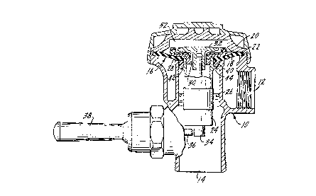
Figure 1 is a partial axial section through a diaphragm
type of flush valve showing the improved refill ring of the
present invention,
Figure 2 is an enlarged plan view of the refill ring
of Figure 1, and
Figure 3 is a section along plane 3-3 of Figure 2
illustrating the relationship between the refill ring and the
flush valve passage within which it fits.
Description of the Preferred Embodiment
U. S. Patent 3,656,499, assigned to the assignee of
the present invention, describes a diaphragm-type flush valve
and a refill ring for use in that flush valve which has been
in commercial use for a number of years. The refill ring was
specifically designed to quiet the closure of the diaphragm upon

its seat during operation of the flush valve. The exterior of
the refill ring has a plurality of grooves which are designed
to reduce water turbulence during closure of the diaphragm
assembly and there is an annular space about the periphery of
the refill ring which forms a passage between the interior of
the flush valve barrel and the exterior of the refill ring.
As the diaphragm assembly is closed water flows through this
passage, with the grooves which form the interior wall of the
passage functioning to reduce turbulence and thus, noise. The
presence of a very large number of vertical grooves in the
periphery of that refill ring made the part expensive to
manufacture and difficult to hold to tolerance. The result
was that the flow of water past the refill ring during closure
varied greatly because of the difficulty of precisely
controlling the size of the passage about the exterior of the
refill ring. The present invention is specifically designed
to control the size of the water passage or passages about the
exterior of the refill ring, but yet using a refill ring which
is relatively inexpensive to manufacture and one which is
extremely reliable in use.
In a preferred embodiment, the present invention relates
to a flush valve, a body having an inlet and an outlet, a
passage connecting the inlet and outlet, a valve seat at one
end of said passage, a diaphragm positioned to control the
flow of water through said passage and to close upon said
seat, a guide member attached to the bottom of said diaphragm
and positioned within said passage, a solid refill ring
attached to said guide member adjacent the diaphragm, said

~ ~4~
,_
refill ring having an outer diameter closely approximating the
inner diameter of the passage, a plurality of recesses formed
in the exterior of the refill ring, closure of said diaphragm
upon said seat moves the refill ring within said passage, the
exterior of the ring being in substantial circumferential
contact with the interior of the passage, whereby the flow of
water past said refill ring is limited to the areas of said
refill ring recesses.
In a further embodiment, the present invention relates to
a solid refill ring adapted to be attached to a diaphragm
assembly, of a flush valve and mounted upon the guide member
of the diaphragm assembly, said refill ring having an outer
diameter approximating the inner diameter of the flush valve
passage adjacent the diaphragm seat, said refill ring having a
plurality of recesses formed in the exterior thereof whereby
closure of the diaphragm upon its seat moves the refill ring
within the flush valve passage, the exterior of the refill
ring being in substantial circumferential contact with the
interior of the flush valve passage whereby the flow of water
past the refill ring is limited to the area of said refill
ring recesses.
In the drawings, a flush valve body is indicated
generally at 10 and has an inlet 12 and an outlet 14. The
diaphragm assembly is indicated generally at 16 and includes a
flexible diaphragm 18 clamped about its periphery between an
internal cover 20 an a shoulder 22 formed in the flush valve
body 10. A guide member 24 is attached to the diaphragm and
extends within a barrel 26 of the flush valve, the barrel
~,...

~2 ~
forming a passage between the inlet and the outlet. At the top
of the barrel there is a seat 28 upon which the diaphragm
assembly closes.
The diaphragm is provided with a central opening 30 within
which is positioned a relief valve 32, the lower end of which,
indicated at 34, is positioned for contact by plunger 36. As
is well known in the art, plunger 36 is operated by movement of
handle 38. The description and function of the flush valve are
more fully described in U. S. Patent 3,656,499.
The refill ring is indicated at 40 and may be formed of a
suitable plastic material, for example Delrin* or Celcon*. The
ring has an inwardly-facing peripheral recess 42 whereby the
ring is mounted upon a shoulder 44 formed on the exterior of
guide member 24. As more clearly indicated in Figure 3, the
outer periphery 46 of the refill ring has a diameter which
closely approximates the inner diameter of barrel 26. Thus,
the refill ring will tightly fit with the barrel when the
diaphragm assembly is in the closed position of Figure 1. The
periphery of the refill ring has a plurality of recesses, the
number may vary, as may the placement of the recesses. In the
embodiments disclosed herein, the recesses are in the form of
flatted areas 48 and there may be six such flatted areas about
the periphery. Again, the particular form of the recess may
vary and other recess configurations such as grooves, notches
or the like, may be equally satisfactory. What is important is
that the periphery of the refill ring, as indicated at 46,
be in tight contact with the interior of the barrel 26 so that
* Trade Marks
t ''~'.
'.'~

during closure of the diaphragm assembly the only water that
flows past the refill ring is that which flows through
recesses 48.
The refill ring may also include, at its outer periphery,
a notch or groove 50 which is downwardly facing, but which may
be upwardly facing if the refill ring is reversed in position,
as is disclosed more fully in the above-mentioned '499 patent.
In operation, the diaphragm is held in the normally
closed position of Figure 1 by the pressure in chamber 52
above the diaphragm. Operation of handle 38 causes its
plunger 36 to contact relief valve stem 34, tilting the relief
valve, reducing the pressure in chamber 52, causing the
diaphragm to lift off of its seat due to pressure at inlet 12.
This opens the passage between inlet 12 and outlet 14.
Release of handle 38 returns the relief valve to its
closed position on the diaphragm. Pressure rises in chamber
52 through a bypass, not shown, in the diaphragm. The
diaphragm will close upon seat 28 near the end of the flushing
cycle and as it does, the refill ring will close the passage
through barrel 26 except for the flow through recesses 48.
The refill ring derives its name from the fact that the small
amount of water that passes around it just before seating of
the diaphragm provides the small refill portion of water
required to seal the trap of the water closet.
Of particular significance in the invention is the use of
a refill ring which tightly fits within the flush valve barrel
or the passage between the flush valve inlet and outlet. When
the diaphragm assembly closes, the periphery of the ring is in

2 ~
'~ -
tight contact with the interior of the barrel, restricting
water flow past the refill ring during valve closure to only
that amount which flows through the recesses. The
configuration of the recesses, in this case flats, may be
easily controlled during manufacture so that a precise amount
of water may flow at this point in the flushing cycle. In
prior refill rings, for example that shown in the '499 patent,
the size of the passage between the exterior of the refill
ring and the interior of the barrel varied considerably due to
manufacturing tolerances. In the present invention the
exterior of the refill ring and the interior of the barrel
need not have close tolerances, providing that the refill ring
fits tightly. Since the ring is plastic and the barrel is
brass, the refill ring may be forced into the barrel during
closure of the diaphragm assembly.
Whereas the preferred forms of the invention has been
shown and described herein, it should be realized that there
maybe modifications, substitutions and alterations thereto.
A

Dessin représentatif
Une figure unique qui représente un dessin illustrant l'invention.
États administratifs

2024-08-01 : Dans le cadre de la transition vers les Brevets de nouvelle génération (BNG), la base de données sur les brevets canadiens (BDBC) contient désormais un Historique d'événement plus détaillé, qui reproduit le Journal des événements de notre nouvelle solution interne.

Veuillez noter que les événements débutant par « Inactive : » se réfèrent à des événements qui ne sont plus utilisés dans notre nouvelle solution interne.

Pour une meilleure compréhension de l'état de la demande ou brevet qui figure sur cette page, la rubrique Mise en garde , et les descriptions de Brevet , Historique d'événement , Taxes périodiques et Historique des paiements devraient être consultées.

Historique d'événement

Description Date
Inactive : CIB de MCD 2006-03-11
Le délai pour l'annulation est expiré 2002-09-06
Lettre envoyée 2001-09-06
Accordé par délivrance 1999-01-19
Inactive : Taxe finale reçue 1998-10-02
Préoctroi 1998-10-02
Lettre envoyée 1998-08-21
Un avis d'acceptation est envoyé 1998-08-21
Inactive : Renseign. sur l'état - Complets dès date d'ent. journ. 1998-08-18
Inactive : Dem. traitée sur TS dès date d'ent. journal 1998-08-18
Inactive : Approuvée aux fins d'acceptation (AFA) 1998-06-23
Exigences pour une requête d'examen - jugée conforme 1995-10-17
Toutes les exigences pour l'examen - jugée conforme 1995-10-17
Demande publiée (accessible au public) 1991-03-19

Historique d'abandonnement

Il n'y a pas d'historique d'abandonnement

Taxes périodiques

Le dernier paiement a été reçu le 1998-08-18

Avis : Si le paiement en totalité n'a pas été reçu au plus tard à la date indiquée, une taxe supplémentaire peut être imposée, soit une des taxes suivantes :

  • taxe de rétablissement ;
  • taxe pour paiement en souffrance ; ou
  • taxe additionnelle pour le renversement d'une péremption réputée.

Les taxes sur les brevets sont ajustées au 1er janvier de chaque année. Les montants ci-dessus sont les montants actuels s'ils sont reçus au plus tard le 31 décembre de l'année en cours.
Veuillez vous référer à la page web des taxes sur les brevets de l'OPIC pour voir tous les montants actuels des taxes.

Historique des taxes

Type de taxes Anniversaire Échéance Date payée
TM (demande, 7e anniv.) - générale 07 1997-09-08 1997-08-20
TM (demande, 8e anniv.) - générale 08 1998-09-08 1998-08-18
Taxe finale - générale 1998-10-02
TM (brevet, 9e anniv.) - générale 1999-09-06 1999-08-11
TM (brevet, 10e anniv.) - générale 2000-09-06 2000-08-09
Titulaires au dossier

Les titulaires actuels et antérieures au dossier sont affichés en ordre alphabétique.

Titulaires actuels au dossier
SLOAN VALVE COMPANY
Titulaires antérieures au dossier
JOHN F. WHITESIDE
Les propriétaires antérieurs qui ne figurent pas dans la liste des « Propriétaires au dossier » apparaîtront dans d'autres documents au dossier.
Documents

Pour visionner les fichiers sélectionnés, entrer le code reCAPTCHA :


Pour visualiser une image, cliquer sur un lien dans la colonne description du document. Pour télécharger l'image (les images), cliquer l'une ou plusieurs cases à cocher dans la première colonne et ensuite cliquer sur le bouton "Télécharger sélection en format PDF (archive Zip)" ou le bouton "Télécharger sélection (en un fichier PDF fusionné)".

Liste des documents de brevet publiés et non publiés sur la BDBC .

Si vous avez des difficultés à accéder au contenu, veuillez communiquer avec le Centre de services à la clientèle au 1-866-997-1936, ou envoyer un courriel au Centre de service à la clientèle de l'OPIC.


Description du
Document 
Date
(aaaa-mm-jj) 
Nombre de pages   Taille de l'image (Ko) 
Description 1998-06-09 6 251
Revendications 1998-06-09 2 68
Abrégé 1993-11-26 1 24
Revendications 1993-11-26 2 67
Dessins 1993-11-26 1 45
Description 1993-11-26 5 206
Dessin représentatif 1999-01-07 1 14
Avis du commissaire - Demande jugée acceptable 1998-08-20 1 166
Avis concernant la taxe de maintien 2001-10-03 1 179
Taxes 1998-08-17 1 48
Correspondance 1998-10-01 1 40
Taxes 1997-08-19 1 41
Taxes 1999-08-10 1 37
Taxes 2000-08-08 1 37
Taxes 1996-08-06 1 44
Taxes 1995-09-05 1 45
Taxes 1994-08-29 1 48
Taxes 1993-08-16 1 34
Taxes 1992-05-14 1 35
Correspondance de la poursuite 1995-10-16 1 32
Correspondance de la poursuite 1998-03-09 3 46
Correspondance de la poursuite 1996-03-24 3 74
Courtoisie - Lettre du bureau 1995-11-02 1 38
Demande de l'examinateur 1998-01-22 1 32