Note : Les descriptions sont présentées dans la langue officielle dans laquelle elles ont été soumises.
BAR CODE ~P~T- NECg RING 2 0 2 5 4 4 6
This invention relates to identification devices
for containers. More particularly, this invention
relates to identification neck rings suitable for
housing bar code labels for use as identification
devices on containers, such as gas cylinders.
Reusable gas cylinders for transporting and
~iRpen~ing pressurized gases and other products are used
in a number of industries. It is often nece~sAry to be
able to identify such containers and their contents.
Labelling the containers so as to identify them with
respect to weight, contents, destination and other
relevant information is a tedious and time-consuming
process which can be greatly facilitated by the use of
coded labels and electronic data entry.
Transport of labelled cylinders also poses some
difficulties. The containers are often stacked
horizontally such that cylinder surfaces roll and
abrade against each other. As a result, it is possible
for valuable labelling information to be obliterated
during transport and handling. Furthermore, once the
cylinders are stacked identification labels are often
hidden and it is not always possible to read the labels
until the cylinders are rearranged or moved.
Identification devices for gas cylinders and other
similar containers are known in the prior art. In U.S.
Patent No. 2,001,679 (Haughey), an inspection tag for a
fire extinguisher is disclosed. In U.S. Patent No.
2,613,462 (Johnson), a fixed identification metal crown
is disclosed for gas cylinders. Other identification
devices are disclosed in U.S. Patent No. 3,079,716
(Riuli), U.S. Patent No. 3,787,993 (Lyon), U.S.
4,282,974 (Quandel), U.S. Patent No. 4,640,031 (Hoek)
and U.S. Patent No. 4,827,643 (Hearst et al.).
2 2~025446
Of these prior art patents, it appears that the
'031 patent of Hoek and the '643 patent of Hearst et
al. are the most pertinent to the invention disclosed
and claimed herein.
Mechanized automatic reading of identification
data (ID data) is now a desired standard in the
industry. One known means for such automatic reading
of identification data is the use of the well-known bar
code label which is readily scanned and decoded by way
of a hand-held wand. This process is referred to herein
as wanding. Such an identification device is disclosed
by Hearst et al ('643), while Hoek et al. ('031) teach a
coding means whereby a plurality of magnetic elements is
distributed over the circumference of a cylinder
container.
Both Hearst et al. and Hoek et al. teach a ringed
label mounting device which is permanently mounted upon
a gas cylinder by thread means. In both of these
patents, the identification label is securely held and
fixed in one position relative to the cylinder.
Unfortunately, fixedly securing the label device in this
way limits access to the label data once the cylinders
are stacked for storage and/or transport, depending on
the orientation of the cylinders. As a result, Hearst
et al. require the use of a plurality of bar-coded
labels evenly distributed about the mounting device, to
improve the ability to read the label when in a cylinder
stack.
To facilitate inventory control, monitoring of
cylinder transport and cylinder reusability, there
remains a need for an accessible label device,
particularly suited for electronic ID data collection.
In accordance with an aspect of the present
invention, there is provided, in combination, an
elongate gas cylinder having a threaded neck portion at
one end thereof and a sloping shoulder portion adjacent
2025446
the neck portion; a closure for the container threadedly
mounted on the neck portion; and an identification
device freely rotatably mounted on the neck portion of
the cylinder between the closure and the shoulder
portion of the cylinder but not removable therefrom
without removing the closure or destroying the integrity
of the device, the identification device comprising (a)
a skirt having an upper extremity and a lower extremity
and flared downwardly and outwardly from the neck
portion of the cylinder in a manner approximating the
shape of the shoulder portion of the cylinder, (b) the
skirt terminating at its lower extremity in a first
integral flange which extends first downwardly and then
inwardly from the lower extremity to engage the
shoulder portion, whereby the identification device
rests on the shoulder portion, (c) the skirt
terminating at its upper extremity in a second integral
flange which extends inwardly from the upper extremity
of the skirt towards the neck portion and to be spaced
therefrom to permit the identification device to be
freely rotated about the neck portion, and (d) a label-
mounting region on the skirt for receiving a label
having identification data thereon.
In the present invention, therefore, the annular
identification device, or bar code neck ring, as
sometimes referred to herein, is freely rotatably
mounted to the cylinder to permit the annular
identification device to be rotated relative to the
cylinder to enable ready access to be had to the
electronic ID data label and thereby a convenient
manner of accessing the data of cylinders in a stack.
The bar code neck ring of the invention is
conveniently formed by molding from suitable plastic
material and provides a desirable surface for applying
identification labels onto containers, such as gas
cylinders. Through the use of such a neck ring, the
.
.,
- 2025446
label no longer clutters up an already heavily-labelled
cylinder shoulder. The use of such a neck ring permits
a standardized label location.
The neck ring is freely rotatable around the neck
S of the cylinder but will not fall off because it is
located between the cylinder and the base of the neck of
the cylinder. This arrangement ensures easy access to
the identification data label mounted on the neck ring
regardless of the orientation of the cylinder. Only a
single bar code label is required, in contrast to the
prior art disclosure of Hearst et al ('643), where the
neck ring is fixed relative to the cylinder.
The bar code, or similar identification data,
label may be rotated into an ideal location for viewing
and optional orientation for wanding. The ability to
freely rotate the ring around the neck of the cylinder
when wanding also decreases wanding time as the label
location can be manoeuvred into optimal location. At
the same time, since the neck ring is maintained in a
fixed location by the cylinder closure, the neck ring
cannot be removed or lost, without first removing the
cylinder closure or destroying the integrity of the neck
ring.
In automated systems, easy access to a bar coded
label is of great advantage as stacks of cylinders may
be wanded after they are already piled, thereby
increasing the efficiency of inventory control.
An important advantage of the present invention is
its simplicity and low cost. A bar code neck ring
according to the invention is simple to manufacture
from plastic material and is readily applied to a gas
cylinder or other container, by slipping it around the
neck before the cylinder closure is screwed on.
Other and further advantages and features of the
invention will be apparent to those skilled in the art
from the following detailed description taken in
2025446
conjunction with the following drawings, wherein:
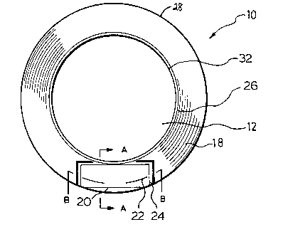
Figure 1 is a plan view of one embodiment of a bar
code label neck ring of the present invention;
Figure 2 is a cross-sectional view of the bar code
neck ring taken along line A-A in Figure l;
Figure 3 is a cross-sectional view of the bar code
neck ring taken along line B-B in Figure 1;
Figure 4 is a side elevational view of the bar
code label neck ring of Figure l; and
Figure 5 is a side elevational view and partial
cross-sectional view of the neck area of a cylinder
illustrating the positioning of the neck ring of Figure
1 thereon.
Referring to the drawings, one embodiment of the
bar code label neck ring identification device of the
present invention is illustrated therein and is
indicated generally by the numeral 10. The device 10
is a one-piece element, which may be made of plastic,
usually by molding, or from any other suitable material
as would be known to one skilled in the art. In a
preferred embodiment, the device 10 is vacuum formed
from sheets of 20 mil PVC.
The device 10 has the general shape, when viewed
in plan, of an annulus with a central opening 12, the
opening being slightly larger in diameter than the
diameter of the neck 14 of a gas cylinder 16 to permit
the device 10 to be freely mounted on the neck 14.
Extending outwardly and downwardly (as seen
particularly in Figure 2) from the opening 12 is a
skirt 18 with a shape approximating that of a shoulder
19 of the cylinder 16.
The skirt 18 has a label mounting region 20 for
receipt of a bar code label 22. The label mounting
region 20 is outlined partially by a raised bead 24, to
assist in locating the bar code label 22 correctly on
the skirt 18.
,,
2025446
The skirt 18 is designed to fit over and generally
follow the shape of the shoulder 19 of the cylinder 16
which takes the form of a nape of the neck 14. The
shape may be modified to accord with the shape of other
containers.
The skirt 18 has an upper extremity 26 and a lower
extremity 28. The skirt 18 terminates at its lower
extremity 28 in a first integral flange 30 which extends
first downwardly and then inwardly from the lower
extremity of the downward portion to engage the shoulder
19 and thereby rest on the shaping surface of the
cylinder 16. The skirt 18 terminates at its upper
extremity 26 in a second integral flange 32 which
extends horizontally inwardly from the upper extremity
26 towards the neck. This second integral flange 32
conforms with the shape of the neck 34 of the cylinder
but is raised away from it to permit the device 10 to be
freely rotatable around the neck 14. In the device 10,
the first integral flange 30 enables the device 10 to
rest on the shoulder 19 of the cylinder 16. The device
10 is sized such that, when the first flange 30 is
resting on the shoulder 19 of the cylinder 16, the bar
code neck ring 10 is located adjacent to but free of
threads 34 used to mount the cap 36 or other closure on
the cylinder 16. When the cap 36 is in place, the bar
code neck ring 10 is free to rotate about the cylinder
neck 14 but cannot become accidentally dislodged by
reason of the presence of the cap 36.
In summary of this disclosure, the present
invention provides a novel freely-rotatable neck ring
upon which a label may be mounted to facilitate
identification and inventory control of gas cylinders
or other suitable containers. Modifications are
possible within the scope of this invention.
~.