Sélection de la langue

Search

Sommaire du brevet 2025689 

Énoncé de désistement de responsabilité concernant l'information provenant de tiers

Une partie des informations de ce site Web a été fournie par des sources externes. Le gouvernement du Canada n'assume aucune responsabilité concernant la précision, l'actualité ou la fiabilité des informations fournies par les sources externes. Les utilisateurs qui désirent employer cette information devraient consulter directement la source des informations. Le contenu fourni par les sources externes n'est pas assujetti aux exigences sur les langues officielles, la protection des renseignements personnels et l'accessibilité.

Disponibilité de l'Abrégé et des Revendications

L'apparition de différences dans le texte et l'image des Revendications et de l'Abrégé dépend du moment auquel le document est publié. Les textes des Revendications et de l'Abrégé sont affichés :

  • lorsque la demande peut être examinée par le public;
  • lorsque le brevet est émis (délivrance).
(12) Demande de brevet: (11) CA 2025689
(54) Titre français: TAMPON
(54) Titre anglais: COVER ASSEMBLY FOR A GROUND OPENING
Statut: Réputée abandonnée et au-delà du délai pour le rétablissement - en attente de la réponse à l’avis de communication rejetée
Données bibliographiques
(51) Classification internationale des brevets (CIB):
  • E02D 29/14 (2006.01)
(72) Inventeurs :
  • GEIGER, ROBERT A. (Canada)
(73) Titulaires :
  • ROBERT A. GEIGER
(71) Demandeurs :
  • ROBERT A. GEIGER (Canada)
(74) Agent: SMART & BIGGAR LP
(74) Co-agent:
(45) Délivré:
(22) Date de dépôt: 1990-09-19
(41) Mise à la disponibilité du public: 1991-03-26
Requête d'examen: 1991-01-18
Licence disponible: S.O.
Cédé au domaine public: S.O.
(25) Langue des documents déposés: Anglais

Traité de coopération en matière de brevets (PCT): Non

(30) Données de priorité de la demande:
Numéro de la demande Pays / territoire Date
07/411,651 (Etats-Unis d'Amérique) 1989-09-25

Abrégés

Abrégé anglais


Abstract of the Disclosure
A cover assembly for a ground opening, such as a
manhole or a storm drain, is disclosed. The cover assembly
includes a frame having a top, a bottom and a tubular
sidewall section which is open to both the top and the
bottom of the frame. An abutment portion protrudes inwardly
into the tubular sidewall section adjacent its bottom. A
core is slidably insertable into the tubular sidewall
section of the frame so that the bottom of the core abuts
against the frame abutment portion. The core includes a
tubular through opening adapted to receive and support a
cover such as a manhole cover or a storm drain cover across
its upper end. The frame is constructed of a metallic
material while the core is constructed of a non-metallic
material, such as plastic, to prevent seizing.

Revendications

Note : Les revendications sont présentées dans la langue officielle dans laquelle elles ont été soumises.


CLAIMS
1. A cover assembly for a ground opening
comprising:
a frame, said frame having a top, a bottom and a
tubular sidewall section, said sidewall section having an
interior wall open to said top and said bottom,
said frame having an abutment portion which
protrudes into said tubular sidewall section adjacent the
bottom of said frame,
a core, said core being slidably insertable into
said tubular sidewall section of said frame so that a bottom
of said core abuts against said abutment portion,
said core having a tubular through opening and
means for receiving and supporting a cover across an upper
end of said core,
wherein said frame is constructed of metal,
wherein said core is constructed of a non-metallic
material.
2. The invention as defined in claim 1 and
comprising means for adjusting the vertical position of said
core with respect to said frame.
3. The invention as defined in claim 2 wherein
said adjusting means comprises shims inserted between said
abutment portion and a bottom of said core.
4. The invention as defined in claim 1 wherein
said core is constructed of plastic.

5. The invention as defined in claim 1 wherein
said tubular section is cylindrical in shape.
6. The invention as defined in claim 1 wherein
said core assembly is a manhole assembly.
7. The invention as defined in claim 1 wherein
said drain assembly is a storm drain assembly, and wherein
said cover includes a plurality of openings formed through
it.
DWS/tlk

Description

Note : Les descriptions sont présentées dans la langue officielle dans laquelle elles ont été soumises.

I' .
I 202~689
COVER ASSEMBLY FOR A GRO~ND CPENING
Background of the Invention
8 I. Field of the Invention
The present invention relates generally to cover
~ assemblies and, more particularly, to a cover assembly for a
~ ground opening, such as a manhole or a storm drain.
I II. Description of the Prior Art
..
The prev1ously known cover assemblies for ground
~ openings, such as manholes and storm drains, typically
comprise a frame constructed of cast iron. The cast iron
w frame includes a circular opening adjacent its top. The
frame is secured to the underground concrete manhole or
storm drain construction by either cementing it or bolting
it into place.
These previously known frames include an annular
O abutment surface adjacent their upper end. A manhole cover
or storm drain cover is then positioned into the frame so
that the annular abutment surface contacts and supports the
cover aajacent the top of the frame. The manhole cover and
storm drain cover (hereinafter collectively referred to as
w
Y manhole cover) are also conventionally constructed of cast
iron.
These previously known cover assemblies suffer
w
~ several disaàvantages. One primary disadvantage of these
~ previously known assemblies is that the cover and/or frame
O may distort slightly after long exposure to both the
elements and physical abuse. Since both the cover and the
frame are constructed of cast iron, such distortion may
cause the cover and frame to seize together. Once the cover
.

202~68~
and frame have seized together, the removal of the cover
from the frame is not only time consuminq, but it may be
even necessary to destroy the cover and replace the cover
with a new one.
A still further disadvantage of these previously
known cover assemblies, and particularly manhole cover
assemblies, is that the manhole cover must be at the same
level as the street level. After time, however, many
T : -
~ streets are repaved or resurfaced with asphalt which raises
10 ~m the level of the street, typically by one and one-half
inches.
.0
Once the level of the street has changed, it is
often necessary to replace the entire manhole assembly.
This procedure, of course, is not only time consuming but
also very expensive. There have, however, been some manhole
Z cover assemblies with means to adjust the vertical heighth
.~
of the manhole cover, but these manhole cover assemblies
with such adjustment means are ex?ensive and have not gained
widespread acceptance.
20 Q Summarv of the Present Invention
~u
z The present invention provides a cover assembly for
a ground opening which overcomes all of the above mentioned
z
disadvantages of the previously known devices.
u
~ In brief, the cover assembly of the present
2~ ~ invention comprises a frame having a top, a bottom and a
O tubular sidewall sect on which is open to both the top and
, bottom of the frame. An annular abutment portion protrudes
into the tubular sidewall section of the frame adjacent its
bottom. Additionally, the frame is secured to the
.. ~ ... . .. . . .
-2-

202~6~
undergrounù concrete manhole or storm drain strocture by
either cementing or bolting the frame in place. The frame
is typically constructed of cast iron.
A non-metallic and preferably plastic core is then
~ slidably insertable into the tubular sidewall section of the
~ frame until the bottom of the core abuts against and is
I supported by the abutment portion of the frame. The core
includes a through opening with an annular abutment surface
~ adjacent its top. This annular abutment surface is adapted
~ to receive and support a manhole or storm drain cover.
wN Since the core is constructed of a non-metallic
w material, any sei2ing between the core and the cover or the
z
core and the frame is completely eliminated. Additionally,
the ver~ical heighth of the core, and thus the effective
o vertical height of the manhole or storm drain cover, can be
Z easily accomplished by placing shims between the bottom of
the core and the frame abutment portion.
Brief Description of the Drawing
~ A better unàerstanding of the present invention
will be had upon reference to the following detailed
z description when read in conjunction with the accompanying
drawing, wherein like reference charac.ers refer to like
Q parts throughout the several views, and in which:
w
~ FIG. 1 is a fragmentary sectional elevational view
~ showing a preferred embodiment of the present invention;
O FIG. 2 is an exploded view of the preferred
embodiment of the present invention;
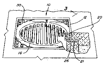
FIG. 3 is a sectional view taken along line 3-3 in
FIG. l; and

~ 2~2~689
,
FIG. 4 is a sectional view similar to the sectional
portion of FIG. 1, but illustrating the use of a shim with
the present invention.
0
~ Detailed Description of a Preferred
5 ^ Embodiment of the Present Invention
oD With reference first to FIGS. 1 and 2, a preferred
I embodiment of the cover assembly 10 of the present invention
is thereshown and comprises a frame 12, a core 30 and a
T : :'
~ typically metal cover 16. The cover 16 shown in the drawing
~ is a manhole cover but it will be understood that it can
also be a storm drain cover. Each of these components will
~O
be described in greater detail.
With reference now especially to FIG. 2, the frame
12 comprises a generally rectangular base 14. A rectangular
O tubular sidewall section 17 extends upwardly from the base
Z 14 and includes an interior wall 18 which is open to both a
top 20 of the frame and the bottom 21 (FIG. 1) of the frame
12 through a circular opening 22. Strengthening ribs 24
also preferably extend between the sidewall section 17 and
~ the frame base 14.
w
z Referring again to FIG5. 1 and 2, an abutment
portion 26 protrudes into the interior Oc the sidewall
D section 18 adjacent the bottom 21 of the frame 12. The
~ circular opening 22 is formed through this abutment portion
25 ~ 26.
O Referring now especially to FIGS. 2 and 3, the core
30 is dimensioned so that it is slidably removably received
within the tubular sidewall section 17 of the frame 12.
Unlike the frame 12 which is constructed of cast iron,

2025~89
, .
however, the core 30 is constructed of a non-metallic
material, such as plastic.
~ The core 30 also includes a circular throughbore 32
having an enlarged diameter portion 34 adjacent its top.
~ The enlarged diameter portion 34 forms an annular abutment
surface 36 adjacent the top of the core 30.
u In operatlon, the frame 12 is secured to an
underground manhole or storm drain structure 40 by
~ cementing, bolting or in any other conventional fashion.
- Thereafter, the non-metallic core 30 is slidably inserted
into the tubular sidewall section 17 of the frame 12 until
, the core 30 abuts against the abutment portion 26 of the
6 frame 12.
c Thereafter, the circular cover 16, such as a
2 manhole or storm drain cover, is positioned within the top
Z of the core 30 so that the cover 16 abuts against and is
N
supporteo by .he annular abutment surface 36 on the core 30.
In doing so, the top of the cover 16 is essentially flush
~ with the top of the core 30 as best shown in FIG. 3.
o
In practice, the effective heighth of the manhole
J
z or storm drain cover 16 can be effectively changed by
changing the vertical position of the core 30 with res?ect
to the frame 12. This can be accomplished by placing shims
~ 42 in between the abutment portion 26 of the frame 12 and
~ the bottom of the core 30 as best shown in FIG. 4.
O A still further advantage of the present invention
is that, due to the metallic, non-metallic, metallic
construction of the frame 12, core 30 and cover 16, seizing
between the cover 16 and the core 30 is completely
eliminated.
, ~' _5_

Z02!j~89
A still further advantage of the present invention
is that the effective height of the cover 16 can be raised
as shown in FIG. 4. This is particularly useful when
O resurfacing of the road, as shown at 50 in FIG. 4, raises
~- 5 ~ the effective height of the road 52.
-
~ Having described my invention, however, many
modifications thereto will become apparent to those skilled
~ in the art to which it pertains witho~t deviation from the
I spirit of the invention as defined by the scope of the
z
10 e appended claims.
m
N I claim:
w
w
w>
¢
t`
o
e
20 D
æ
r
z
e
w
s
25 e,
D
LL I
IL I

Dessin représentatif
Une figure unique qui représente un dessin illustrant l'invention.
États administratifs

2024-08-01 : Dans le cadre de la transition vers les Brevets de nouvelle génération (BNG), la base de données sur les brevets canadiens (BDBC) contient désormais un Historique d'événement plus détaillé, qui reproduit le Journal des événements de notre nouvelle solution interne.

Veuillez noter que les événements débutant par « Inactive : » se réfèrent à des événements qui ne sont plus utilisés dans notre nouvelle solution interne.

Pour une meilleure compréhension de l'état de la demande ou brevet qui figure sur cette page, la rubrique Mise en garde , et les descriptions de Brevet , Historique d'événement , Taxes périodiques et Historique des paiements devraient être consultées.

Historique d'événement

Description Date
Inactive : Inventeur supprimé 2001-12-04
Le délai pour l'annulation est expiré 1994-03-19
Demande non rétablie avant l'échéance 1994-03-19
Inactive : Demande ad hoc documentée 1993-09-20
Réputée abandonnée - omission de répondre à un avis sur les taxes pour le maintien en état 1993-09-20
Demande publiée (accessible au public) 1991-03-26
Toutes les exigences pour l'examen - jugée conforme 1991-01-18
Exigences pour une requête d'examen - jugée conforme 1991-01-18

Historique d'abandonnement

Date d'abandonnement Raison Date de rétablissement
1993-09-20

Taxes périodiques

Le dernier paiement a été reçu le 

Avis : Si le paiement en totalité n'a pas été reçu au plus tard à la date indiquée, une taxe supplémentaire peut être imposée, soit une des taxes suivantes :

  • taxe de rétablissement ;
  • taxe pour paiement en souffrance ; ou
  • taxe additionnelle pour le renversement d'une péremption réputée.

Veuillez vous référer à la page web des taxes sur les brevets de l'OPIC pour voir tous les montants actuels des taxes.

Historique des taxes

Type de taxes Anniversaire Échéance Date payée
TM (demande, 2e anniv.) - petite 02 1992-09-21
Titulaires au dossier

Les titulaires actuels et antérieures au dossier sont affichés en ordre alphabétique.

Titulaires actuels au dossier
ROBERT A. GEIGER
Titulaires antérieures au dossier
S.O.
Les propriétaires antérieurs qui ne figurent pas dans la liste des « Propriétaires au dossier » apparaîtront dans d'autres documents au dossier.
Documents

Pour visionner les fichiers sélectionnés, entrer le code reCAPTCHA :


Pour visualiser une image, cliquer sur un lien dans la colonne description du document. Pour télécharger l'image (les images), cliquer l'une ou plusieurs cases à cocher dans la première colonne et ensuite cliquer sur le bouton "Télécharger sélection en format PDF (archive Zip)" ou le bouton "Télécharger sélection (en un fichier PDF fusionné)".

Liste des documents de brevet publiés et non publiés sur la BDBC .

Si vous avez des difficultés à accéder au contenu, veuillez communiquer avec le Centre de services à la clientèle au 1-866-997-1936, ou envoyer un courriel au Centre de service à la clientèle de l'OPIC.


Description du
Document 
Date
(aaaa-mm-jj) 
Nombre de pages   Taille de l'image (Ko) 
Revendications 1991-03-26 2 41
Page couverture 1991-03-26 1 12
Abrégé 1991-03-26 1 20
Dessins 1991-03-26 1 41
Description 1991-03-26 6 183
Dessin représentatif 1998-07-24 1 11
Taxes 1992-09-18 1 26
Correspondance de la poursuite 1991-01-18 1 20
Courtoisie - Lettre du bureau 1991-06-19 1 21