Note : Les descriptions sont présentées dans la langue officielle dans laquelle elles ont été soumises.
2025916
SHUTTLE GUIDE FOR A STORAGE AND RETRIEVAL MACHINE
Field of the Invention
This invention relates to a guide for the shuttle of a
storage and retrieval machine and, in particular, to a
shuttle guide which guides the shuttle during its movement
transverse to the mast of the storage and retrieval machine
along a smooth path which has an upward or a downward
inclination when the shuttle is xespeatlvely mo~ing outward
from or toward the storage and retrie~al machine.
Backqround of the Invention
Storage and retrieval machines are commonly used in
material and inventory storage facilities for storing items
in and retrieving the items from the facilities. Typical of
such acilities are warehouses having storage racks of
substantial height arranged along aisles in which the
storage and retrieval machines travel to various designated
aisle locatlons. The machines are self-propelled by
electric drive motors and provided with signals rom a
remote source to direct them to each aisle location.
At each designated aisle location, there are a number
of storage racks arranged in a vertically stacked manner.
Each storage rack is typically suitable for holding a single
box, pallet, or other items. The storage and retrieval
machine inserts items into or retrieves items from each rack
by moving a carriage along a vertical mast opposite th,e
2025~1fi
vertically stacked racks to a position opposite a designated
rack and, by means of a shuttle, moving an object to be
stored into the rack or retrieving an object to be moved
elsewhere from the rack. A shuttle typically comprises
several plates, a base or first one of which is affixed to
the carriage. The balance of the plates are extendable from
the carriage in a telescoping fashion into a bottom area of
the rack space to transfer the box or pallet from the
carriage to the raak or remo~e the box or pallet from the
rack and on to the carriage.
The telescopically extendible plates are supported by
multiple roller sections moveable in guide ways with either
the roller sections or the guide ways for each plate being
mounted on an immediately adjacent underlying plate. In
extending from the carriage into the bottom area of the rack
space or retracting from the rack space to the carriage, the
clearance between the guide rollers and the guide ways,
along with material deflection caused by the wither of the
shuttle, causes the shuttle to deflect below the theoretical
straight line extension. The amount of deflection increases
when a load object is on the shuttle. The historical method
to compensate for the difference in deflection, loaded
versus unloaded, has been to increase the distance the
shuttle is lifted above the rack elevation at which the load
is placed. Increasing the distance the shuttle is lifted
requires increasing the rack clearance above the load
object, thus increasing the space required to store the
202~16
object. This additional vertical space is required for each
vertically stacked rack space to thereby substantially
increase the height of the entire rack or result in less
rack spaces. To eliminate this wasted space problem,
shuttle guide mechanisms have been developed which move the
extended plates upward at an angle to deposit or pick up a
load object and correspondingly move the extended plates
downward to retract a load object from a rack. The present
invention is an improvement in this type o shut~le guide
for storage and retrieval machines.
Summarv of the Invention
It is an object of this invention to provide a guide
for the shuttle of a storage and retrieval machine which
guides the shuttle along an inclined and smooth extending
and retracting path during an ob~ect retrieving or
depositing operation of the shuttle.
The invention is accomplished by providing a storage
and retrieval machine having a shuttle mounted on a aarriage
movable on a mast for carrying ob~ec~s to and from overhead
storage spaces. The mast is mounted on a base and the mast
and base are travelable to designated locations. The
shuttle comprises plate means supported on the carriage
including first and second plates movable relative to each
other in opposite transverse directions relative to the mast
for depositing load objects in and retrieving the objects
from the storage spaces. As the plate means move outward
~ . , -~ ., .
2~2~
from the mast and toward a storage space, the weight of the
shuttle and any load object carried by the plate means will
cause downward deflection of the plate means. The plate
means and thereby the shuttle are guided toward and away
from the storage rack spaces by a first guide member having
a downward facing straight guide surface extending in the
transverse directions of movement of the plate means and by
a second guide member having an upward facing inclined guide
surface with the inclined guide surface being inclined
upwardly relative to one of the transvQrse directions. A
first guide roller means is positioned in engagement with
the straight guide means and a second guide roller means is
positioned such that it is engageable with the inclined
guide surface and guides one of the moveable plates in an
upward inclination direction toward a storage space.
Thereby downward deflection of the plate means caused by the `
weight of the shuttle and the load is counteracted.
The upward facing surface of the second guide member
may comprise a middle portion and an end raised portion,
with an inclined ramp connecting the middle and raised end
portions. The first and second guide roller means may
comprise a plurality of spaced apart guide rollers with a
first portion of the guide rollers being positioned
intermediate a second portion of the guide rollers and the
first portion of the guide rollers being spaced from the
middle portion of the upward facing guide surface.
During the movement of the first and second plates in
202~16
transverse extending and retracting directions, one of the
intermediate guide rollers moves from a position engaging
the raised end portion of the guide surface to a position at
which it disengages from and engages with the upward facing
guide surface during the transverse movement of the one
intermediate plates. At the disengaging and engaging
position of the one intermediate guide roller, another of
the intermediate guide rollers has a position in supporting
engagemant with the inclined ramp such that the hQight of
the one intermediate guide roller at its two positions is
substantially the same. Thus, the movement of the guide
rollers from engagement with the guide surfaces thereby the
corresponding extension and retracting movement of the plate
means is smooth and without any significant abrupt dip or
jogging movement.
Brief DescriPtion of the Drawinas
Further objects and advantages will appear when taken
in conjunction with the accompanying drawings, in which:
Fig. 1 is a side elevation view of a storage and
retrieval machine utilizing a guide for a shuttle according
to the invention;
Fig. 2 is a front end elevation view of the storage and
retrieval machine shown in Fig. 1 with the shuttle extended
into a storage rack;
Fig. 3 is a cross-sectional plan view, partially broken
away, taken along lines 3-3 of Fig. 2 and illustrating the
shuttle;
202~
Fig~ 4 is an end elevation view, partially broken away,
of the shuttle shown in Fig. 3;
Fig. 5 is a cross-sectional plan view, partially broken
away, taken along lines 5-5 of Fig. 4;
Fig. 6 is a side-elevation view of the shuttle shown in
Fig. 4; and
Flgs. 7-11 are schematic side elevation cross-sectional
views, similar to the vlew of Fig. 6, illus~ratlng the
shuttle in ive different positions during its extending and
retracting operation.
Detailed Descri~tion of the Invention
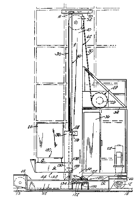
Referring genera~ly to Figs. 1 and 2 of the drawings, a
storage and retrieval machine is shown having a base 2, a
mast 4 mounted on and extending upwardly from the base 2, a i,
mast connecting structure 10 for connecting the mast to the
base, a carriage 6 movable along the length of the mast 4 to
selected vertical positions, and a shuttle 8 mounted on the
carriage 6. A front wheel 13 and a rear wheel 12 are
mounted-on the base 2 and roll along a rail 14 supported on
a foundation lS and running through an aisle path 17 in a
storage area such as a warehouse having stacked storage
racks 16. Upper guide wheels 18 mounted on the upper 40 of
the mast 4 engage an upper guide rail 20 to guide the
storage and retrieval machine along the rail 14 and maintain
the machine in an upright position. A motor 22 mounted on
the base 2 drives the rear wheel 12 so that the storage and
2~2~
retrieval machine travels along the rail 14 to selected
locations in the aisle path 17 adjacent to the stacked
storage racks 16.
At each selected aisle location of the storage and
retrieval machine the carriage 6 is driven in vertical
directions to a selected one of the storage racks 16 where
the shuttle 8 is driven in directions transverse to the mast
4 into the selected storage rack 16 to deliver or retrieve a
load ob~eat such as box 24 shown in ~lgs. 1 and 2. At a
position in the rack undernëath the load, the movement o
the shuttle includes an upward component when extending into
the rack to pick up the load, and includes a downward
component when retracting from the rack to deposit the load
in the rack. The carriage 6 is driven by a motor 26 acting
through a rope drum assembly 28, both mounted on a frame 34
affixed to the base 2 and the mast 4, and driving a rope 30
connected to the carriage 6 and wrapped around a sheavé 32.
A control 36 is also mounted on the base 2 for controlling
the operation and movement to the selected locations of the
base 2, the carriage 6 and the shuttle 8. Suitable means
(not shown) are provided for supplying electrical power to
the motors mounted on the base and carriage and control
signals to the control 36.
The base 2 comprises two lengthwise parallel spaced
apart L-shaped members 42 and 44 and a top plate 54 which
extends along a substantial middle portion of the length of
the base 2 and is affixed to the members 42 and 44 by
202~916
suitable means such as welding. The base 2 also includes
end trucks 46 and 48 attached to opposite ends of the
members 42 and 44. The wheels 12 and 13 are respectively
mounted on the trucks 46 and 48. The mast 4 comprises an
elongated tube 60 having a rectangular cross-section and an
additional elongated member 62 affixed along its length to
the tube 60. The tube 60 has a front wall 50, a rear wall
52, a lateral wall 56 and a lateral wall 64. In addition to
the upper end 40, the mast ~ has a lower end 58 supported by
the mast connecting stru~ture 10.
The mast connecting structure 10 includes an upper
plate means 70, a lower plate means 100, and connecting
means 120 connecting the plate means 70 and 100 together.
The upper plate means 70 is affixed to the mast 4 and the
lower plate means 100 is affixed to the base 2. The
connecting means 120 includes a plurality of nut and bolt
means 122 for connecting the upper and lower plate means 70
and 100 and thereby mounting the mast 4 on the base 2.
plurality of support tubes 134 are positioned coaxially on
the bolt means 122. The bolt means 122 draw the upper plate
means 70, against the support of the tubes 134, toward the
lower plate means 100 upon the tightening of the bolt means
to connect the mast to the base.
With reference to Figs. 1-3, the carriage 6 includes a
frame 132 upon which the shuttle 8 is mounted and to which
is connected the rope 30 for moving the carriage 6
vertically along the mast 4 in response to the operation of
- ~2~16
the motor 26 and rope drum assembly 28. The carriage 6 is
movably supported on the mast 4 by means of upper support
rollers 112, 114, and 116, 118 rotatably mounted on an upper
section 136 of the frame 132, and by means of lower support
rollers 124, 126 and 128, 130 mounted on a lower section 138
of the frame 132. The rollers 114, 124, and 118, 128
respectively engage the lateral walls 64 and 56 of the tube
60, the rollers 112, 116 both engage the wall 52 of the tube
60, and the rollers 126, 130, both engage thc wall 50 of the
tube 60.
Referring to Figs. 4-6, the shuttle 8 comprises a motor
and gear drive 80 mounted on the lower section 138 of the
carriage frame 132, a shuttle drive 200, a lower base plate
150, an intermediate plate 160, a top plate 180, and a
shuttle guide assembly 250. The shuttle guide assembly 250
includes side support walls 152 and 154 mounted on base
plate 150, side support walls 184 and 186 projecting
downwardly from top plate 180, guide tracks 170 and 172
mounted on the lateral edge sectlons 166 and 168 of
intermedlate plate 160, supp~rt gulde rollars 156 and 158
respectively rotatably mounted on walls 152 and 154 of base
plate 150, and support guide rollers 187, 188, 189, 190 and
191, 192, 193, 194 respectively rotatably mounted on walls
184 and 186 of top plate 180.
The base plate 150 is affixed to the lower frame
sections 138 of the carriage frame 132. The intermediate
plate 160 is supported for movement transverse of the mast 4
~2~
on the support walls 152 and 154 by the projection into and
engagement of the rollers 156 and 158 respectively with the
guide ways 174 and 176 of the respective guide tracks 170
and 172. The top plate 180 is supported for movement
transverse of the mast 4 on the walls 184 and 186 by the
projection into and engagement of the rollers 187-190 and
191-194 with the guide ways 196 and 198 of the respective
guide tracks 170 and 172.
The shuttle drive 200 includes a drive drum 202 and an
idler sheave 204 mounted for rotation on the base plate 150,
a cable 206, and drive chain means 208 and 210. The cable
206 is wrapped around the drive drum 202 and the idler
sheave 204 and is attached to the intermediate plate 160 at
opposite ends 82 and 84 of the plate 160. The drive drum
202 is selectively rotatabl~ driven in opposite rotational
directions by the gear and motor drive 80. The drive chain
means 208 includes a rotatable sprocket 212 rotatably
mounted on the intermediate plate 160 and pro~ecting through
a slot 232 in the plate means 160. A roller chain 234
wraps around the sprocket 212 and attaches to the base plate
150 at the end 86 of the base plate and to the top plate 180
at the end 90 of the top plate. The drive chain means 210
has a sprocket 214 rotatably mounted on the intermediate
plate 160 at the end 82 of the plate 160 which projects
through a slot 240 in the plate means 160. A roller chain
242 wraps around the sprocket 214 and attaches to the base
plate 150 at the end 88 of the base plate and to the end 92
202~91~
of the top plate 180.
In the operation of the shuttle 8, the intermediate
plate 160 is extended transversely away from the mast 4
along the guide tracks 170 and 172 from its retracted
position shown in Fig. 6 by rotation of drive drum 202 in a
first direction such that the cable 206 pulls the plate 160
in a direction away from the carriage 6. As the
intermediate plate 160 is moved in a dlrcction away from the
carriage 6 by the operatlon o~ drum 202 and cable 206, the
sprocket 212 also moves away from the carriage 6. Since the
chain 234 is attached to the base plate 150, which is
stationarily mounted on the carriage 6, the sprocket 212
will rotate and pull the chain 234 in an outwardly direction
to thereby also move the top plate 180 along the guide
tracks 170 and 172 outwardly away from the carriage 6 and in
a direction transverse to the mast 4. The shuttle 8 is
thereby extended from the carriage 6 to the extended
position shown in Fig. 2. When the drive drum 202 is
rotated in a second dlrectlon oppo~lte to the irst rotation
direction, the cable 206 pulls the intermediate plate 160
toward the carriage 6. The sprocket 214, which is mounted
on the intermediate plate 160, moves toward the carriage 6
with the intermediate plate 160 and is rotated so that the
chain 242 pulls the top plate 180 toward the carriage 6 in a
direction transverse to the mast 4 along the guide tracks
170 and 172. The shuttle 8 is thereby returned to its
retracted position in which the plates 160 and 180 are both
11
202~16
in ~heir positions on the carriage 6 as shown in Fig. 4.
With reference to Figs. 7-11, the guide track 172 and
support guide rollers 191-194 illustrate the positions of
the rollers 191-194 and 187-190 respectively, relative to
the guide tracks 172 and 170 as the shuttle 8 is moved
transversely outward from and toward the mast 4 and extended
into and retracted from a rack 16. Since the guide rollers
187-190 move through positions in guide way 196 of track 170
corresponding to those of rollers 191-194 in gulde way 198
of track 172 as the shuttle 8 is extended and retracted,
only the track 172 and the movement and positions of rollers
191-194 will be described in detail herein. The guide way
198 o the track 172 includes a vertical wall 216, an upper
guide surface 218 which preferably has a straight length,
and a lower guide surface 220. The lower guide surface 220
includes inclined portions 222 and 224 respectively adjacent
the ends 226 and 228 of the guide way 198, a straight middle
portion 230 adjoining the inclined portions 222 and 224 and
which is not inclined relative to the portions 222 and 224,
and may also include straight end p~rtions 236 and 238
respectively immediately adjacent the ends 226 and 228 of
the guide way 198. The end portions 236 and 238 may be
parallel to the middle portions 222 and 224. The support
guide rollers 191-194 project into the guide way 198 as
shown in Figs. 4 and 5 and engage the guide way 198 to
support the top plate 180.
In the retracted position of the shuttle 8 as shown in
12
202~91~
Figs. 6 and 7, in which the plates 180 and 160 overlie the
plate 150 and are centered on the carriage relative to the
view of Fig. 6, the spaced apart end rollers 191 and 194
engage the upper guide surface 218 and are respectively
positioned just inwardly of the narrow exit ends 226 and 228
of the guide way 198. The middle rollers 192 and 193,
located intermediate the rollers 191 and 194, engage the
middle portion 230 of the lower guide surface 220 and are
spaced from the upper guide surface 218. In this first or
rstracted position of the shuttle 8, the top plate 180
desirably has a horizontal position. As the top plate 180
is moved by the shuttle drive means 200 transversely away
from the mast 4 and towards a stack space 16, the support
guide roller 191 exits from the narrow exit end 226 of the
guide way 198, as shown in Fig. 8. This movement also
results in the roller 192 beginning movement up the inclined
portion 222 of the lower guide surface 220 which causes the
roller 193 to be lifted off of the middle portion 230 of the
lower guide surface, also as shown in Fig. 8. The shuttle
is now in a second position, slightly extended transversely
of the mast 4 from the carriage 6 and supported by the
roller 192 ~ngaging the inclined surface 222 and the roller
194 engaging the upper guide surface 218. The top plate 180
is slightly inclined upwardly in the direction of a stack
space.
Continued extension of the top plate 180 transversely
from the mast 4 toward a storage rack 16 moves the support
13
202~
guide rollers 191-194 to their positions shown in Fig. 9 in
which roller 191 is well away from the guide way 198, the
middle roller 192 has moved upward on the inclined portion
222 of the lower guide surface 220 and is in the narrow end
226 of the guide way, middle roller 193 has moved upward
slightly on the inclined portion 222, and roller 194
continues to engage upper guide surface 218. Due to the
upward movement of the roller 193 on the inclined portion
222, the roller 193 5tarts to carry 90me of the load of the
shuttle. As the roller 193 moves upward on inclined portion
222, it may also lift the roller 192 a small distance
preferably no greater than the clearance space between the
roller 192 and the upper guide surface 218. In order to
enable the slight lifting of the roller 192 to assist with
the assumption the shuttle load by the roller, the distance ,
between the rollers 192 and 193 must be such that the
movement of the roller 193 along the inclined portion 222
will not lift the roller 192 more than the clearance space
between the roller 192 and the surface 218 prior to the
exiting of roller 192 from thc narrow end 236. In the
position of the shuttle as shown in Fig. 9, the load of the
shuttle is carried substantially by rollers 194 and 193 and
the inclination of the top plate 180 has increased due to
the movement of the roller 192 further upward on the
inclined portion 222 and the beginning of the upward
movement on the inclined portion of the roller 193.
In Fig. 10, the rollers 191-194 and the guide way 198
14
20~
are shown in a fourth position of the shuttle in which
roller 192 has exited the narrow end 236 of the guide way
198 and is out of engagement but adjacent to the end 236.
The roller 193 has moved further up the inclined portion 222
of the lower guide surface 220. Because the roller 193
assumes all or at least a substantial portion of the weight
o~ the load of the shuttle prior to the exiting of the
roller 192 from the narrow end 236, the exiting of the
roller 192 from the end 236 will be smoo~h and wl~hout any
substantial dip or abrupt changes in its path. The load of
the shuttle is carried by the rollers 194 and 193 and the
top plate 180 is further inclined.
In Fig. 10, the position of the rollers 191-194 and the
guide way 198 are shown in a fifth position of the shuttle
in which the roller 192 is well away from the guide way 198
and the roller 193 is positioned in engagement with the
guide way 198 in the narrow end 236. The load of the
shuttle continues to be supported by the rollers 194 and 193
and the plate 180 is inclined to its maxlmum incllned
position in a bottom area o a s~orage rack 16 and in
engagement with a load such as a box 24 in the rack 16, as
shown in Fig. 2.
In moving in a transverse direction toward the mast 4
and retracting from a storage rack the shuttle and its
rollers 191-194 move through the positions substantially as
shown in Figs. 7-11 as described above in a reverse
order. At the position shown in Fig. 10, the roller 192
2~2~91~
W-_l be adjacent to but disengaged from the end 226 of the
guide way and will engage and enter the end 226 in a smooth
manner as it moves to the position shown in Fig. 9.
The movement upward of the plate 180 in the rack space
beneath the box 24 results in a lifting of the box 24
sufficient to disengage it from the rack 16 upon retraction
of the shuttle to thereby enable the retrieval of the box 24
on the plate 180 from the storage rack 16. In the
retraction of the shuttle from the storage rack 16 the plate
180 and thereby the rollers lgl and 192 may have a
relatively greater downward deflection due to the load of
the box 24 in addition to the load of the shuttle itself.
However, the path of the rollers 192 and 191 adjacent the
narrow end 236 of the guide way 198 will be substantially
the same as their position during extension of the shuttle.
It will be understood that the foregoing description of
the present invention i5 for purposes of illustration only
and that the invention is susceptible to a number of
modifications or changes none of which entail any departure
from the spirit and scope of the present invention as
defined in the hereto appended claims.
16