Sélection de la langue

Search

Sommaire du brevet 2026615 

Énoncé de désistement de responsabilité concernant l'information provenant de tiers

Une partie des informations de ce site Web a été fournie par des sources externes. Le gouvernement du Canada n'assume aucune responsabilité concernant la précision, l'actualité ou la fiabilité des informations fournies par les sources externes. Les utilisateurs qui désirent employer cette information devraient consulter directement la source des informations. Le contenu fourni par les sources externes n'est pas assujetti aux exigences sur les langues officielles, la protection des renseignements personnels et l'accessibilité.

Disponibilité de l'Abrégé et des Revendications

L'apparition de différences dans le texte et l'image des Revendications et de l'Abrégé dépend du moment auquel le document est publié. Les textes des Revendications et de l'Abrégé sont affichés :

  • lorsque la demande peut être examinée par le public;
  • lorsque le brevet est émis (délivrance).
(12) Demande de brevet: (11) CA 2026615
(54) Titre français: ROUE DE TRACTION POUR PIVOTS CENTRAUX ET ELEMENTS ANALOGUES
(54) Titre anglais: TRACTION WHEEL FOR CENTER PIVOTS AND THE LIKE
Statut: Réputée abandonnée et au-delà du délai pour le rétablissement - en attente de la réponse à l’avis de communication rejetée
Données bibliographiques
(51) Classification internationale des brevets (CIB):
  • A01G 25/09 (2006.01)
  • B60B 15/02 (2006.01)
(72) Inventeurs :
  • BOCKERMAN, BERNARD J. (Etats-Unis d'Amérique)
(73) Titulaires :
  • BERNARD J. BOCKERMAN
(71) Demandeurs :
(74) Agent:
(74) Co-agent:
(45) Délivré:
(22) Date de dépôt: 1990-10-01
(41) Mise à la disponibilité du public: 1991-03-30
Licence disponible: S.O.
Cédé au domaine public: S.O.
(25) Langue des documents déposés: Anglais

Traité de coopération en matière de brevets (PCT): Non

(30) Données de priorité de la demande:
Numéro de la demande Pays / territoire Date
414,675 (Etats-Unis d'Amérique) 1989-09-29

Abrégés

Abrégé anglais


Abstract of the Disclosure
A traction wheel adapted to be mounted on an irrigation tower
includes a pair of axially spaced apart annular rims having ground
engagement surfaces which are inclined radially and axially
inwardly toward one another. A plurality of wedge shaped lugs.
interconnect the rims, which lugs are circumferentially spaced
apart to form openings between the rims and lugs. Several of the
lugs have one side extended radially inwardly of the rims to serve
as a spoke. The inner ends of the spokes are connected to a hub
suitable for mounting the wheel on an axle assembly.

Revendications

Note : Les revendications sont présentées dans la langue officielle dans laquelle elles ont été soumises.


The embodiments of the invention in which an exclusive property or
privilege is claimed are defined as follows:
1. A traction wheel adapted to be mounted on an axle
assembly, said traction wheel comprising,
a pair of axially spaced apart annular rims, said rims presenting
ground engagement surfaces which are inclined radially and
axially inwardly toward one another,
a plurality of generally wedge shaped lugs connected to and
extending between said pair of rims in circumferentially spaced
apart relation, thereby to form openings through said wheel
between said rims and adjacent pairs of lugs,
each lug including loading and trailing sides with respect to the
direction of rotation of said wheel,
one side of a first plurality of said lugs extending generally
radially inwardly of said rims to serve as a spoke therefor,
and
hub means connected to said one side of said first plurality of
lugs, said hub means including means for mounting said wheel on
an axle assembly.
2. The traction wheel of claim 1 wherein each lug is
generally V-shaped with an apex directed radially outwardly.
3. The traction wheel of claim 2 wherein at least one lug has
an opening through the apex thereof.
4. The traction wheel of claim 3 wherein said opening is
generally axially centered on said lug.
5. The traction wheel of claim 3 wherein all of said lugs
have an opening through the apex thereof.

6. The traction wheel of claim 2 wherein said one side has a
radially inner end and further comprising a bushing connected to
said inner end and directed with its axis generally parallel to the
axis of said wheel, hub means including a plurality of mounting
holes alignable with said bushings for securement thereto by
respective fastening means extended through said aligned mounting
holes and bushings.
7. The traction wheel of claim 6 wherein said bushing is
axially offset relative to the center of said one side.
8. The traction wheel of claim 7 wherein said hub means is
adapted for connection to said bushings at either of opposite ends
of said business thereby to vary the position of said rims axially
relative to said hub means.
9. The traction wheel of claims 8 wherein said hub means
includes axially oppositely facing first and second sides, said hub
means being adapted for connection to said axle assembly with either
of said opposite first and second sides facing said axle assembly,
thereby to further vary the position of said rims axially relative
to said hub means.
10. The traction wheel of claim 1, wherein each lug includes
outer edges which taper radially and axially inwardly in matching
relation to said spaced apart rims.
11. The traction wheel of claim 1, wherein said one side of
said plurality of lugs is notched such that the lower most end of
said one side comprising an extension of only a portion of the width
of said one side at a position radially outwardly of said notch.
12. The traction wheel of claim 1, wherein the leading and
trailing sides of a second plurality of said lugs are formed as
substantially the mirror image of one another.
13. The traction wheel of claim 12, wherein at least one lug
of said second plurality of lugs is interposed between adjacent lugs
of said first plurality of lugs.
14. The traction wheel of claim 1, wherein said one side of
said first plurality of lugs is inclined relative to a true radius
through either of opposite ends of said one side.

15. In combination,
an irrigation tower including a pair of power driven axle
assemblies each axle assembly having a mounting plate on a free
end thereof, and each mounting plate having a series of
circumferentially spaced apart fastener means adapted for mounting
a traction wheel on said mounting plate,
a pair of traction wheels, each traction wheel comprising,
a pair of axially spaced apart annular rims, said rims
presenting ground engagement surfaces which are inclined
radially and axially inwardly toward one another,
a plurality of generally wedge shaped lugs connected to and
extending between said pair of rims in circumferentially
spaced apart relation, thereby to form openings through
said wheel between said rims and adjacent pairs of lugs,
each lug including leading and trailing sides with respect to
the direction of rotation of said wheel,
one side of a first plurality of said lugs extending generally
radially inwardly of said rims to serve as a spoke
therefor, and
hub means connected to said one sides of said first plurality
of lugs, said hub means including a series of
circumferentially spaced apart holes registered with said
fastener means such that said fastener means are
operative to mount said hub on said mounting plate.

16. The combination of claim 15 wherein each lug is generally
V-shaped with an apex directed radially outwardly and at least one
lug has an opening through the apex thereof.
17. The combination of claim 15, wherein said one side of
said first plurality of lugs is notched such that the lower most
end of said one side comprises an extension of only a portion of
the width of side one side at a position radially outwardly of said
notch.
18. The combination of claim 15, wherein the leading and
trailing sides of a second plurality of said lugs are formed as
substantially the mirror image of one another.

Description

Note : Les descriptions sont présentées dans la langue officielle dans laquelle elles ont été soumises.

2~2~
aye us I ho In I
The present invention it directed generally to an improved
traction wheel and more particularly to such a wheel particularly
adapted for supporting arid moving a center pivot irrigation tower on
and across soft wet ground.
In a center pivot irrigation system, water from a centrally
located well us directed through a long boo which it pi~otQd around
the well by drive wheels on the spaced apart tower which support
the boom. The towers may be 15 or 20 feet high, with as much as 60
feet between towers and zany sections may be added together so that
the single pivot can irrigate a quarter cation ox land. The towers
are generally equipped with large rubber tire such like on a
conventional farm tractor. When the tires rotate on muddy ground
resulting Roy the irrigation water, or natural causes, the tires
tend to push the mud to the idea and head of the tire so that the
action of the tire it constantly that of climbing out of a hole.
In muddy condition, the tires tend to create a greater build up
ahead of the tire, which may become Jo severe that the tire cannot
climb out of it on it own power. That essentially shut down the
stem until a tractor can by brought out to tow two tower ahead.
Accordingly, principal object Or the prune inven~isn is to
provide an improved traction wheel.
Another ob~ct it to provide a traction wheel particularly
suited or advancing an irrigation boom tower across muddy ground.
Another object it to provide an improved traction wheel which
tend to rid on top ox muddy ground and minimize thy buildup of mud
ahead of the notating wheel.
another object it to provide an improved traction wheel which
I generally self claiming a it Crusoe muddy ground
Another object it to provide a traction wheel having
circumferential spaced lugs d~lgned two be Allah pulled prom the
Bud a thy wheel roll forwardly.

nether object is Jo provide a traction wheel having
transversely extended and circumferentiLally spaced apart traction
lug designed to dissipate any vacuum formed between the lug and
the muddy ground.
Another object is to provide a traction wheel which it
adjustable to vary the axial position of the wheel rim relative to
the hub for universal mounting on non-uniform equipment of different
manufacturer.
Another object of the invention it to provide a traction wheel
which is simply and rugged in construction, economical to
manufacture and efficient in operation.
Summary of the Invention
The traction wheel of the invention include a pair of axially
spaced apart annular Roy presenting ground QngagQmsnt surfs
which are inclined radially end axially inwardly toward one another
to Norm the ground into a mound on which the wheel rut A series
of wedge shaped lugs era connected to and extended between the rim
in circumferential spaced apart relation to Norm openings through
the wheel between the ring and the adjacent pairs of lug. Each lug
ha inclined leading and trailing side with the respect to the
direction ox rotation ox the wheel. One side ox several of thy lugs
extend radially inwardly prom the rims to serve as a spoke for the
Rome. The int~rlor ends of those extended sides ox the lug are
connected to a hub which it adapted to be mounted on a conventional
axle amiably.
Each lug on thy rims it generally V-shaped with an apex
directed radially outwardly. An opening it wormed through the apex
ox the lug both to incrQa~e traction and to dissipate any vacuum
ore between the lug and muddy ground a thy lug it pulled prom
the mud on the back side ox a rolling wheel.
The extended lug idea which serve as puke or thy rim Jay be
permanently welded to the hub or removably and ad~uRtably connected
to hub for varying the axial position ox the rim relative to
the hut. ~iff~rsnt manufacturers ox center pivot tower have
different ~peci~ication~ or the preferred axial position of the
zoom relative to eye hub. my providing Boeing on thy interior
end of the spoke and by axially offsetting those interior Ends
relative to the rim, at lea t for ad~ustment3 to by jade to thy
position ox the rim relative to the hub. For example, the hub may
by mounted to either end ox the bushings end thy Wesley may have
either ox its oppose idea awing the hub.

J
Byway description I thy Roy
Figure 1 is a perspective view of a traction wheel according to
the invention;
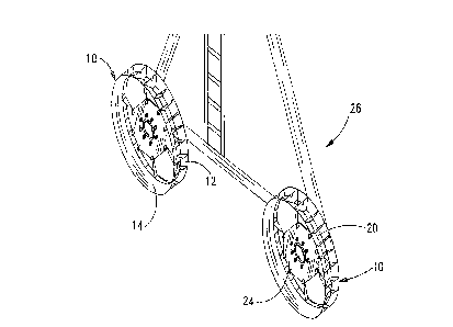
Figure 2 it a partial p~r~pectiY~ Yo-yo of ho lower portion of
an irrigation tower having a pair of traction wheel of the
invention mounted thereon;
Figure 3 is a partially sectional end elevation Al view of the
traction wheel of the invention mounted on an axle assembly;
Figure 4 is an enlarged perspective View of a spoke forming lug
of the wheel;
Figure 5 is an enlarged perspective view ox a simple lug ox the
wheel; and
Figure 6 it partially ~ctional side elevation Al Yo-yo I the
traction wheel of the invention.
Thy traction wheel 10 ox thy present invention it illustrated
in pharaoh 1 a including a pair ox spaced apart annular rip 12 and
14 which are fru~toconically aped 50 as Jo be inclined radially
and axially inwardly toward owns another. Thy rim are connected
together by a series ox spoke oaring wedge shaped lug 16 and a
err ox si~plQ wedge-~haped lug 18. ho lugs 16 and 18 cooperate
with thy rims to ox opening through thy wheel 10 b~twQen the rim
and ad~ac2nt pairs ox lug. Such openings 20 arrowhead H ~el~-cleaning
action or the wheels by allowing mud and dirt packed betoken the
rim to par through the opening in ripen to continued rotation
ox the wheel.
ash spoke oaring lug 16 ha on exuded side 22 connected lo a
hub 24 which adapted Jo mounted on convention axle embowel.

guru 2 owe an irrigation vower I having a pair of traction
wheels 10 mounted thereon or supporting a moving toe tower across
field. The connection ox the tower I to each wheel lo is by an
axle assembly I as shown in figure 3. Axle assembly 28 includes a
power driven axle 30 having a mounting plate 32 on the free end
rough. Mounting plate I has a series of oircumferentially spaced
apart holes alienable with registered holes I in the hub I for
Sacramento of the wheel to the mounting plate 32 in the conventional
fashion by bolt assemblies 36.
Figure 4 illustrates the spoke forming lug 16 which is
generally Shaped with an apex 38 directed radially outwardly. Lug
16 has a short side 40 adapted to terminate at the interior edge ox
thy rims whereas the extended side 22 extends radially interiorly
from the rims to serve a a spoke for the wheel. The interior end
42 of the extended side may be welded or otherwise rigidly secure to
the hub for a permanent non-universal connection. Alternatively, thy
interior end 42 may be removably and adoptable connected to the hut
for a generally universal connection adapted to accommodate mounting
of the wheel on irrigation towers of different manufacturers.
One type ox universal connection it lllu~trated in figure 3 and
4 wherein the interior end 42 ox the extended rids 22 of lug 16 ha
a bushing 44 formed thereon. Furthermore, the extended side 22 it
notched as at 46 such that the lower most end 48 ox the extended
idea 22 comprises an extension of only a portion ox thy width of
side 22 at a position radially outwardly of the notch 46.
Accordingly, the bushing 44 it axially onset relative Jo the center
of lug 16.
erring to figure I Tao prevents four alternate mounting
positions of the wheel 10 relative to the axle mounting plats 32.
First, thy hub 24 is adapted or connection to the bushings 44 at
lather of opposite end of the busheling thereby to vary the po~iticn
Shea the rim axially relative to two hub. Furthermore, toe hub
lncl~lde~ axially oppositely facing first and second side 50 and 52
and thy hub 24 I dotted for connection to thy axle mounting plats
I with steer ox two opposite first and second idea 50 and 52
fazing the axle mounting plate, throb to further vary thy position
of thy rim 12 and 14 axially r31ative to the hub 240
A owe in figure I on or morn imply lug 18 Jay be
intrepid between adjacent pair ox pow forming lugs 160
simple tug it illustrate in inure 5 wherein the leading and
trailing idea 54 and 56 are wormed as substantially the mirror
image of one another. Each wide has outer edge 58 and 60 which
taper radially and axially inwardly in watching relation to thy
spaced apart rim 12.

Referring to figures 4 and 5, it it seen that both these spoke
forming lugs 16 and simple lugs 18 have respective openings 62 and
64 through the apex thereon, preferably at a transversely centered
position thereon. The openings 62 and 64 both provide increased
traction for the lugs and also verve to dissipate any vacuum formed
between the lug and soft ground a the lug it pulled out the of the
ground in response to rotation of the wheel lo
The number and arr~ngament of lugs on thy wheel Jay be varied
according to any selected pattern. Figure 6 illiterate on
arrangement wherein adjacent pairs of spoke forming lugs 16 asp
oppositely directed and connected to common bushings 44. Each pair
of spoke forming lug ha a pair of simple lug interposed in
between them. The result it a 32 lug wheel. Other contemplated
arrangement include providing a simple lug 18 between each adjacent
pair ox spoke worming lugs 16, or providing a 24 lug wheel wherein a
simple lug 18 is provided between alternate pair of spoke forming
lugs with 16 spoke worming lug being provided. The extended sides
ox the spoke forming legs era preferably inclined relative to a true
radius through either of opposite ends of the spoke worming lug 16
whereby torque it built into the wheel.
The wheel a thug d2~Cri~Qd it non-directional and the V-shaped
of the wedge further prevent mud prom being picked up in response
Jo rotation ox the wheel. Should the wheel ox the inanition become
stuck, a gable may by run under the wheel and stayed to the ground
so that thy lug openings 62 will engage the cable to enable the
wheel to crawl up thy cable toward thy stake and thereby free the
tower and implement by the USQ~0~ its own power.
Herr materiel from which the wheel is formed go no critical
to the invention, a preferred embodiment ha the rim formed of
quarter inch steel plate and spokes or lug formed of 3/16~h inch
steel plate. A 43N diameter it preferred for the wheels 60 what
eye could be operated in tandem with conventional rubber lyre
carrying wheels.
Whereat the invention a been shown and de~crlbed in connection
with a proofread embodiment Thor, it it apparent that many
addition, mod~flcation~ and substitutions may be Audi which are
within the intended broad scope ox the appended claims.

2 3 .) .
For example, where the lug are shown with the apex thereof
dispo~Pd a the outer circumferential edge ox the rim, it may be
preferred to extend the lugs raid ally ol.ltwardly of the rim Jo that
the wheel Howe three point contact on f slat hard ground or a smooth
concrete spill-way for better rewaken fur climbing.
Thus there ha been shown and descried an Lmprotred traction
wheel which accompll~3hes at least all of the twitted object.

Dessin représentatif
Une figure unique qui représente un dessin illustrant l'invention.
États administratifs

2024-08-01 : Dans le cadre de la transition vers les Brevets de nouvelle génération (BNG), la base de données sur les brevets canadiens (BDBC) contient désormais un Historique d'événement plus détaillé, qui reproduit le Journal des événements de notre nouvelle solution interne.

Veuillez noter que les événements débutant par « Inactive : » se réfèrent à des événements qui ne sont plus utilisés dans notre nouvelle solution interne.

Pour une meilleure compréhension de l'état de la demande ou brevet qui figure sur cette page, la rubrique Mise en garde , et les descriptions de Brevet , Historique d'événement , Taxes périodiques et Historique des paiements devraient être consultées.

Historique d'événement

Description Date
Inactive : CIB de MCD 2006-03-11
Le délai pour l'annulation est expiré 1996-04-01
Demande non rétablie avant l'échéance 1996-04-01
Réputée abandonnée - omission de répondre à un avis sur les taxes pour le maintien en état 1995-10-02
Inactive : Demande ad hoc documentée 1995-10-02
Demande publiée (accessible au public) 1991-03-30

Historique d'abandonnement

Date d'abandonnement Raison Date de rétablissement
1995-10-02
Titulaires au dossier

Les titulaires actuels et antérieures au dossier sont affichés en ordre alphabétique.

Titulaires actuels au dossier
BERNARD J. BOCKERMAN
Titulaires antérieures au dossier
S.O.
Les propriétaires antérieurs qui ne figurent pas dans la liste des « Propriétaires au dossier » apparaîtront dans d'autres documents au dossier.
Documents

Pour visionner les fichiers sélectionnés, entrer le code reCAPTCHA :


Pour visualiser une image, cliquer sur un lien dans la colonne description du document (Temporairement non-disponible). Pour télécharger l'image (les images), cliquer l'une ou plusieurs cases à cocher dans la première colonne et ensuite cliquer sur le bouton "Télécharger sélection en format PDF (archive Zip)" ou le bouton "Télécharger sélection (en un fichier PDF fusionné)".

Liste des documents de brevet publiés et non publiés sur la BDBC .

Si vous avez des difficultés à accéder au contenu, veuillez communiquer avec le Centre de services à la clientèle au 1-866-997-1936, ou envoyer un courriel au Centre de service à la clientèle de l'OPIC.

({010=Tous les documents, 020=Au moment du dépôt, 030=Au moment de la mise à la disponibilité du public, 040=À la délivrance, 050=Examen, 060=Correspondance reçue, 070=Divers, 080=Correspondance envoyée, 090=Paiement})


Description du
Document 
Date
(aaaa-mm-jj) 
Nombre de pages   Taille de l'image (Ko) 
Revendications 1991-03-29 4 127
Abrégé 1991-03-29 1 15
Dessins 1991-03-29 2 49
Description 1991-03-29 6 282
Dessin représentatif 1999-07-13 1 11
Taxes 1994-09-29 1 32
Taxes 1993-09-30 1 22
Taxes 1992-09-30 1 19