Note : Les descriptions sont présentées dans la langue officielle dans laquelle elles ont été soumises.
~ $ ~
HUANG. 01A - PATENT
PACl~AGING SYSTE:II FOR Sq'RING LIGHTS
Background of the Invention
The present invention pertains to a space-saving
packaging system for strings of lights.
Conventional means for packaging light strings includes
the use of styrofoam boxes and molded plastic sheets.
Styrofoam boxes, molded with a prescribed number of separate
compartments, aline the lights in several long rows. The
packager inserts the lights into the individual compartments
coiling the string of wire between the rows. The plastic
sheets similarly hold a prescribed number of lights
individually in place using molded tabs. The lights are
laid in long rows with the string of wire coiled between
these rows.
Several problems currently plague these conventional
packaging means. First, they are difficult to package.
Both means loosely coil the string of electrical wire
between the rows of lights. These loose coils tend to move
:: . . ~
about during the packaging process thereby further
complicating the packaging procedure.
Second, the conventional means wastes packaging space.
With lights individually held in long rows laid side by side
and the string of wire coiled in between these rows, these
forms~ of packaging tend to occupy a large horizontal area.
Such~form of packaging further does not reduce its vertical
dimension as dimension isi dictated by the height of the
electrical plug. Accordingly, these forms of packaging do
not minimize their cubic packaging volume.
Finally, both are restricted to a prescribed number of
lights in the string. Accordingly, the packager must keep
on hand several sizes of these packaging means to
accommodate the packaging of light strings containing a
different number of lights in a string, for example 35, 50,
or 100 bulbs in a string.
; ~ `
~ c~ ~ J
^
-2-
Summary of the Invention
An apparatus is provided for the packaging of light
strings, wherein a module holds a number of liqht. The
module may be attached with a like module such that the
assembly clamps the coiled wire extending from the lights
held by the lower module. Securing the coils of wire in
this manageable position thereby eases the packaging
operation.
A plurality of modules may be stacked and attached in
an over-lapping row to reduce their combined stacking
height. Assembling in this shingle-like manner, the wires
extending from the lights held by the lower module are
integrated into the structural assembly to support the
upper module along a portion of its base. The upper module
is thereby positioned at an angle relative to the lower
module. When a third module is attached in the same manner
to the upper module, an overlapping assembly is thus
formed. A plurality of modules assembled in such a fashion
reduces the space needed for packaging and eases the
packaging operation.
The degree of overlap between the mod~les dictates the
height of the assembly. The minimum cubic packaging volume
is obtained by overlapping the rows such that their
combined height is about the width of a standard electrical
plug, as this dimension controls the minimal vertical
parameter of the packaging. This dimension is
approximately equivalent to the height of three modules
stacked vertically.
Any number of modules may be combined to accommodate a
variety of light strings differing in the number of lights
contained in the string. Therefore, the packager need only
stock the one type of module to package light strings with
varying number of lights.
Brief Descrip~ion of the Drawinas
Figure 1 is a perspective view of the invention;
Figure 2 is a perspective view showing the invention
in operation;
`, . . ! . ~ ~ ', ' , ,
.. , .. ~ ' .
,~' ' ' ~ ' ' :
-3-
Figure 3 is a side-elevation of the invention in
operation. -
Description of the Preferred Embodiment
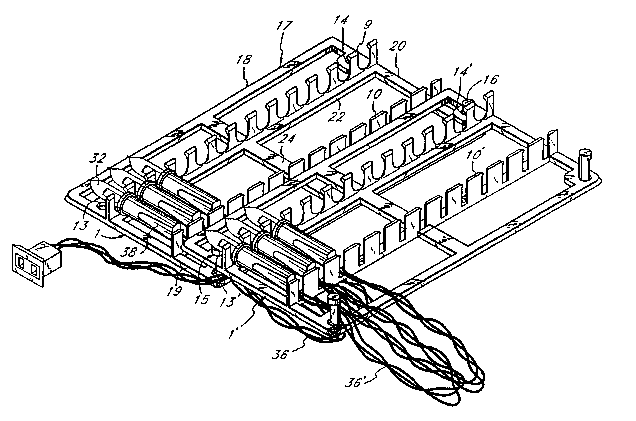
Shown in Figure 1 is a module 1 comprising a
5 supporting base or frame 17 having a generally rectangularshape. The outer periphery of the frame is formed by a
forward strut-like member 18 spaced from and substantially
parallel to a rear strut-like member 21, and joined by a
pair of strut-like side members 19 and 20. The frame 17
10 further includes a rib 22 spaced from a rib 23, with both
ribs extending substantially parallel to the struts 18 and
21. The ribs 22 and 23 are further supported by a rib 24
extending parallel to the side struts 19 and 20.
The rib 22 supports a plurality of upwardly extending,
15 spaced fingers which form light bulb holders 9 arranged in
a row 11. The space 30 between each adjacent pair of
fingers is adapted to receive a single light bulb 32, as
seen in Figures 2 and 3. The rib 23 supports a plurality
of vertically extending wire holders 10 arranged in a row
20 12, with the space 34 between each pair of holders being
adapted to receive the wires 36 extending from each bulb.
The center line of each light bulb holder space 30 is
approximately aligned with the center line of each wire
holder space 34. The distance between the rows 11 and 12
25 is slightly greater than the length of a fixture 38
supporting the bulb 32, such that this fixture is
positioned between the rows 11 and 12, as seen in Figures 2
and 3.
A pair of spaced, vertically extending posts 15 and 16
30 are positioned symmetrically on the corners of the frame 17
formed by the side struts 19 and 20 and the rear strut 21,
which is on the wire side of the module. Further, it can
be stated that the posts are between the outer edge of the
strut 21 and the row of wire holders 12. Holes 13 and 14
35 are symmetrically positioned in the frame struts 19 and 20
on the bulb side of the module, and between the leading
strut 18 and the row 11 of light bulb holders 9. The
t, ~, , . . . ... , , ' .. ' . ` ' ' .` . . ~ ' .~' ' ` .
2~2~S~
placement of the holes 13 and 14 and the posts 15 and 16 is
such that the distance X between t~e center line of the
holes 13 and 14 and the outer edge of the strut 18 is less
than the distance Y between the center line of the posts 15
and 16 and the row of wire holders 12.
The module 1, with all its elements, is preferably
formed using conventional plastic molding processes into a
one-piece component. Preferably, the plastic employed is
stiff but yet somewhat flexible so that a bulb 32 can be
snapped into the light bulb holder 9 and will be retained
there by frictional fit, separated from an adjacent bulb.
As best seen in Figure 1, the posts 15 and 16 have a
cylindrical shape at their top portions 15a and 16a. At a
short distance from the upper surface of the posts and
extending downwardly to the frame struts is a portion lSb
and 16b having generally a semi-cylindrical cross-section.
Thus, there is essentially formed a notch or relief lSc and
16c, with a shoulder 15d and 16d being formed at the
intersection between the upper cylindrical portion 15a and
16a and the lower semi-cylindrical portion lSb and 16b.
The notches lSc and 16c both face outwardly away from the
opposing post.
In use of the module in packaging lights, a string of
lights is positioned, as illustrated in Figure 2, wherein
it can be seen that a light buIb 32 is snapped into a light
holder 9 with the tubular light fixture 38 extending
between the light holders 9 and the wire holders 10, and
with the wire 36 extending through the wire holder 10. A
series of bulbs 32 are positioned in side by side relation
with the wires 36 of a group of adjacent bulbs being neatly
coiled ad;acent to the wire holders, with the coils
extending beyond the rear strut 21.
After one modu}e is filled in this fashion, a second,
upper module 1' is positioned above the lower module 1 with
the leading portion of the upper module extending over the
rear portion of the lower module 1 in overlapping, or
shingle-like fashion. The holes 13 and 14 of the upper
2 ~
module 1' are aligned with and snapped onto the posts 15
and 16 of the lower module 1. The diameter of the posts is
slightly larger than the diameter of the holes so that a
friction fit is obtained. Also, the distance between the
center line of the posts may be slightly less than the
distance between the center line of the holes.
Consequently, once the upper module is snapped onto the
lower one, the shoulders 15d and 16d on the posts of the
lower module tend to engage the upper surface of the upper
module frame to thereby keep the modules assembled or
latched together such that the frame of the upper module
does not slip off the posts of the lower module. The
height of the notches 15c and 16c thus limits the
separation of two assembled modules. In this position, the
frame member 18' of the upper module 1' clamps the coils 36
extending from the lights supported by the lower module.
A series of light bulbs 32 are attached to the upper
module 1' in a fashion similar to that described for the
lower module 1. Alternatively, the lights for the upper
module 1' can be assembled to it bef~re the upper module is
attached to the lower module.
As best seen in Figure 3, the wires of the lower
module support the leading portion of the upper module, and
the rear portion of the upper module angles downwardly at
an angle relative to the lower module frame rather than
parallel to it. When a third module is attached to the
upper module in a manner similar to that described above, a
shingle-like assembly is formed with the modules being
integrated as a single packaging assembly and with the
wires of one module supporting the leading portion of the
ad;acent module. The modules overlap about one thread and
thus the effective horizontal dimension of each module is
only about two-thirds the length of the side struts of a
module. Since the wires of the string of lights of one
module extend essentially completely under the adjacent
upper module, each module filled with lights, including the
wires, is overlapped to about two-thirds of its dimension
' ' ' . - ' ' ," ~ ~, ~ ' ` : ' '::
: ' . ' . ' ' ~ ' .. . . . ,, , ,
~ `
by the module above it. The rearward-most module of a
group of modules of course does .not have its wires
overlapped. Similarly, the leading module, as seen in
Figure 3, does not have its lights in an overlapped
arrangement.
With this arrangement, it can be seen that the height
or vertical thickness of the stack is less than the height
of three of the modules. Advantageously, the thickness of
an assembly of overlapped or shingle-like modules is not
much thicker than the electrical plug for the string of
lights such that the thickness of a relatively flat box for
containing an assembly of a string of lights is about the
same as the thickness of the box that would be employed for
a single layer of bulbs. Thus, it can be seen that the
overlapping of the modules in the manner described
minimizes their cubic packaging volume.
Another advantage of the arrangement is that no other
packaging material is required in that the resilient wires
together with the bulb holders satisfactorily support the
individual bulbs to prevent breakage.
While the modules are shown in a particular size, they
can be made smaller or larger as desired. However, modules
may be attached in cide-by-side relation by suitable means
if an increase in the number of modules in that direction
is desired. Preferably, only a single size module is
utilized with the modules being assembled to create the
desired packaging size. This minimizes the ~anufacturing
expense.