Note : Les descriptions sont présentées dans la langue officielle dans laquelle elles ont été soumises.
CA 02027688 2002-10-11
63293-3287
1
PROCESS FOR THE CATALYTIC CRACKING OF A HYDROCARBON OIL
The present invention relates to a process for the
catalytic cracking of a hydrocarbon oil wherein a
gas/hydrocarbon oil mixture is introduced into the reactor
by means of at least one device which comprises at least one
supply means of which the wall comprises openings, the
hydrocarbon oil is introduced into the supply means and
mixed with an at least partly surrounding gas which enters
under pressure the supply means through the openings in the
wall thereof.
In one aspect the invention provides catalytic
cracking reactor comprising at least one device for
introducing a gas/hydrocarbon oil mixture into the reactor
which device comprises at least one tubular supply means of
which the tubular wall comprises openings, through which
openings, when in use, gas can enter the supply means from a
space surrounding the tubular supply means to be mixed with
the hydrocarbon oil present in the tubular supply means.
According to another aspect of the present
invention, there is provided a catalytic cracking reactor
comprising a bottom part which bottom part comprises a
substantially vertical vessel provided with inlet means for
introducing catalyst particles, fluidization means and at
least one device for introducing a gas/hydrocarbon oil
mixture into the reactor located above the inlet means for
introducing catalyst particles which device comprises at
least one tubular supply means arranged onto a wall of the
vertical vessel, wherein a tubular wall of the at least one
tubular supply means comprises openings, through which
openings, when in use, gas can enter the supply means from a
space surrounding the tubular supply means to be mixed with
CA 02027688 2002-10-11
63293-3287
is
the hydrocarbon oil present in the tubular supply means
before emanating from the tubular supply means into the
vertical vessel.
According to a further aspect of the present
invention, there is provided a use of the reactor described
herein for the catalytic cracking of a hydrocarbon oil
wherein a gas/hydrocarbon oil mixture is introduced into the
reactor.
In this way the hydrocarbon oil is advantageously
mixed with the gas before entering the reactor. As a result
thereof an optimum distribution of hydrocarbon oil over the
catalyst particles is obtained when the hydrocarbon oil is
contacted with the catalyst particles in the reactor. Thus
an excellent performance of a catalytic cracking unit can be
established.
It has been found that suitable mixing of the
hydrocarbon oil and the gas can be attained if the
gas/hydrocarbon oil mixture comprises gas in an amount of
0.1-50 %wt on hydrocarbon oil, preferably 1-15 %wt on
hydrocarbon oil.
CA 02027688 2000-10-04
63293-3287
2
Preferably, the mixing of the hydrocarbon oil and the
gas is carried out in such a way that the gas/hydrocarbon oil
flow velocity (m/s) ratio is in the range of 2-30, whereby the
gas flow velocity is defined as the velocity of the gas
calculated in the openings in the wall of the supply means.
Preferably, the gas/izydrocarbon oil flow ratio is in the range
of 5-15.
The process according to the present invention is
preferably carried out in such a way that the pressure of the
gas entering the supply means is in the range of 2-15 bar abs,
preferably in the range of 5-10 bar abs. Suitably, the
gas/hydrocarbon oil mixture enters the reactor with a velocity
of 20-400 m/s. In the process according to the present
invention various gases can be applied. The gases which can
suitably be applied in the process according to the present
invention comprise for snstance the hydrocarbon gases
comprising four or less carbon atoms, refinery gases (including
HZS), steam and/or any mixture thereof. Preferably, use is made
of steam.
Suitably, the present process is carried out using a
device for the introduction of the hydrocarbon oil which
comprises more than one supply means as described hereinbefore.
Suitably, the upstream end of the device for
introducing the hydrocarbon oil is located above an inlet means
for introducing catalyst particles.
The openings in the supply means of the device to be
used in the process according to the present invention are
suitably located near the upstream end of the supply means.
Suitably, the openings are substantially regularly
arranged in at least one plane perpendicular to the central
longitudinal axis of the supply means. Preferably, the
CA 02027688 2000-10-04
63293-3287
2a
openings are symmetrically arranged in said plane(s).
Preferably, at least 4 openings are symmetrically arranged in
said plane ( s ) .
Suitably, the device as applied in the process
according to the present invention comprises tubular supply
means.
- 3 -
In a preferred embodiment of the process according
to the present invention the hydrocarbon oil is
introduced by means of more than one device as
described hereinbefore, for instance by four of these
devices.
If the hydrocarbon oil is introduced by means of
more than one device, the devices are suitably
substantially regularly arranged in at least one plane
perpendicular to the central longitudinal axis of the
reactor. Preferably, the devices are symmetrically
arranged in said place(s). Suitably, at least 4 devices
are symmetrically arranged in said plane(s). Suitably,
the devices are arranged in at least two of said
planes. Tf the devices are arranged in more than two of
said planes, the planes are suitably substantially
regularly spaced from each other along the length of
the reactor. Preferably, the planes are arranged at
substantially equal distances from each other.
Suitably, all the planes comprise the same number of
devices. Preferably, the devices are arranged in each
plane in such a way that the devises of two
neighbouring planes are staggeredly arranged with
respect to each other.
The bottom part of a riser reactor comprising the
device to be used in the process according to the
present invention and suitable embodiments of said
device for introducing the hydrocarbon oil into the
reactor are described hereinafter, using Figures 1-3 in
which reference numerals relating to corresponding
parts are the same.
7Cn Figure 1 a longitudinal section of the bottom
part of a fluid catalytic cracking riser reactor is
schematically shown which can suitably be used in the
process according to the present invention.
~0~~~~~~
In Figure 2 a longitudinal section of the upstream
end part of the device for introducing the hydrocarbon
oil into the reactor as depicted in Figure 1 is
schematically shown in more detail.
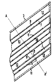
In Figure 3 a cross-section at AA' of the device
as depicted in Figure 2 is schematically shown.
The bottom part of the fluid catalytic cracking
riser reactor as depicted in Figure 1 comprises a
substantially vertically vessel (1) provided with an
inlet means (2) for introducing catalyst particles, and
four devices (3) (of which only two have been shown)
for introducing hydrocarbon ail into the riser reactor.
The riser reactor furthermore preferably comprises
fluidization means (4), for instance in the form of a
ring-shaped ar annular fluidization means, provided
with regularly spaced fluidization gas openings (e. g.
nozzles (5)) 'through which a fluidization gas, for
instance steam, introduced via fluidization gas inlet
means (6) emanates into the bottom section (12) of the
reactor.
In Figures 2 and 3 the upstream end part of the
device (3) for introducing the hydrocarbon oil into the
reactor is shown in mare detail. The device (3)
comprises tubular supply means (7) having openings (~)
in their walls (~), and a space (10) arranged between
the tubular supply means (7) and wall (11) of the
device (3).
The process according to the present invention
using the riser reactor of which only the bottom part
is shown in Figure 1 is normally carried out as
follows.
A stream of catalyst particles in a carrier gas (e. g.
originating from a catalyst regenerator) is introduced
through inlet means (2) into the bottom section (12) of
the riser reactor. The catalyst particles are fluidized
2~9~"~~~8
and transported upwardly by means of for instance steam
introduced via line (6) into ring-shaped or annular
fluidization means (4) provided with regularly spaced
fluidization nozzles (5). A stream of a hydrocarbon oil
is introduced into supply means (7) of the device (3)
and mixed with a stream of steam which enters from
space (10) under pressure with a high velocity the
supply means (7). 'The upwardly flowing fluidized mass
of catalyst particles is excellently mixed with the
l0 mixture of the hydrocarbon oil and steam obtained
emanating with a high velocity from device (3).
The use of device (3) in the process according to
the present invention results in a very uniform mixing
of the fluidized catalyst particles and the hydrocarbon
oil. As a result of this uniform mixing a very
attractive performance of the catalytic cracking unit
can be obtained.
Tn Figure 1 the devices (3) are arranged onto the
wall of the vassal (1). Tt will be understood, however,
that the devices) (3) can also suitably be arranged
differently, for instance substantially centrally in
the bottom section (12) of the riser reactor or at
other suitable places in the riser reactor or stripping
zone of a catalytic cracking reactor.
In Figures 2 and 3 the tubular supply means (7)
are arranged parallel with respect to each other. Tt
will be clear, however, that the supply means (7) can
also suitably arranged in a different manner, for
instance the supply means (7) may diverge from each
other in the direction of the upstream end of the
device (3).
The mixing of the gas and the hydrocarbon oil in~
the supply means (7) is preferably carried out at
temperatures in the range of 50-600°C, more preferably
in the range from 100-400°C.
CA 02027688 2000-10-04
- 6 -
The process for the catalytic cracking of a
hydrocarbon oil according to the present invention is
preferably carried out at a temperature from 400-800C and
pressures from 1-10 bar abs. It will be understood that the
present process can suitably be carried out using any fluidized
catalytic cracking catalyst, however, zeolite-containing
catalysts are preferred.
The hydrocarbon oil which can suitably be
converted in the process according to the present
l0 invention comprises heavy hydrocarbon oils, for
instance atmospheric or vacuum distillates, cycle oils
and slurry oils, deasphalted oils, atmospheric and
vacuum residues, thermally cracked residues, asphalts
originating from various kinds of deasphalting
processes, synthetic residues and hydrocarbon oils
originating from hydroconversion processes, tar sands
and shale oils of any source, and/or any mixture
thereof.
The present invention is illustrated by means of
the following Example.
Example
A feed stream of a straight run heavy hydrocarbon
oil (a Conradson carbon content of about 5 %wt) enters
supply means (7) of the riser reactor as partly
depicted in Figure 1 at a temperature of 260°C and is
mixed in the supply means (7) with a stream of steam,
which enters space (10) at a temperature of 260°C and a
pressure of 6 bar. The resulting oil/steam mixture
flows with a velocity of more than 70 m/s through the
upstream end of supply means (7) into the reactor
vessel (1), which is operated at a pressure of 3 bar
and a temperature of 520°C. Regenerated zeolite Y based
catalyst particles are introduced via inlet (2) at a
temperature of 705°C into the reactor vessel (1)
2U~r~~t~~
_ 7
wherein the catalyst particles are contacted with the
oil/steam mixture.
The product yields on feed obtained in the above
Example are summarized in the Table as shown
S hereinbelow.
Table
product Yields
C1-C~ cwt 17.8
C5-221°C cwt 51.0
221-370°C cwt 17~0
370°C~ cwt 7.2
coke cwt 7.0
It will be clear from the results presented in the
Table shown hereinabove, indicating an attractive yield
of products in the gasoline range, that a heavy
hydrocarbon oil can very suitably be subjected to the
l0 process according to the present invention.