Note : Les descriptions sont présentées dans la langue officielle dans laquelle elles ont été soumises.
2~2849~
~ BO 36216
Electric traction system.
The present invention relates to an electric traction system,
in particular for a vehicle or vessel, comprising a set of traction
motors and traction storage batteries. In particular the present
invention relates to an electric traction system without an addi~
tional internal-combustion engine and without power supply through
trolley wires.
Owing primarely to the weight and limited capability of
storage batteries, such electric vehicles and vessels have general-
ly been more expensive and less acceptable. Thi~ limited capability
of the storage batteries limits the driving range between recharg-
ing in yeneral to about 60 km. Recharging the batteries requires
much time and apart from the vehicle base station there are only
few r~charging stations.
The object of the present invention is to provide an electric
traction system which in particular gives the vehicle or vessel a
wider range between recharging the batteries as well as a higher
efficiency. Therefore according to the present invention the trac-
tion system comprises range extending devices for charging or
backing up the storage batteries.
Preferably these range extending devices are batteries which
can be connected to electrical supply means, such as the mains or
solar cells for charging said range extending batteries and battery
switch means to connect these range extending batteries in parallel
with the main storage batteries for charging or backing up the
storage batteries.
The capacity of the range extending batteries is about 20% of
the capacity of the main storage batteries.
Instead of a range extending battery also a range extending
vegetable oil motor/generator can be used for charging or backing
up the storage batteries.
Also the traction system comprises a battery charging control
syste~, which switches the range extending battery and the main
storage batteries in parallel between traction battery voltages of
1.57 and 2.41 Volt per cell.
3~ The traction system of the present invention preferably also
202~4~3
comprises a second set of traction motors, which can be connected
to the storage batteries separately from the first above mentioned
set of traction motors. soth sets of traction motors can drive the
same vehicle gear box.
Preferably each traction motor of one set comprises a thermo-
static device controlling common traction ~otor switch means, such
that upon exceeding a predetermined temperature in one traction
motor of a set, this traction motor set will be switched off and
the other traction motor set will be switched on. Also each trac-
tion motor set comprises load detecting means, controlling said
common traction motor switch means, such that upon exceeding a
predetermined load in one traction motor set the other traction r~
motor set will be switched on in parallel to the first traction
motor set.
The motors of each set are DC-motors and each set may com-
prise one or more motor.
The present invention provides for the incorporation of
advanced electrical EV-components to power a standard four-wheeler
car and placed together in an original design configuration. Hence
the invention provides a cost ef$ective commercially viable sturdy,
safe, silent, non-polluting means of transport.
The power pack comprising battery charger means, charged by
the mains or solar cells, storage battery, electronic speed con-
troller means, motor, gear box, differential transmission to the
front or rear wheels, all are located within the vehicle. Thé
power pack is selected to suit a given car and is mounted in the
car ensuring for easy service access, safety and efficient per-
formance economics.
The main traction storage batteries preferably will be one of
two types, i.e. lead acid, or nickle iron type. Each of the above
battery systems offer various levels of cost, energy power, life
weight, complexity and packaging economics.
The traction motors preferably are of the state of art type,
i.e. a series field DC-motor with 80% efficiency and four pole
configuration and in particular designed for traction.
The electronic speed controller means is built out of Field
Effect Transistors, which is a state of art technology. The elec-
.. : .- . . : :: : . ~:: . ~ ,
2~2~3
tronic speed cont~oller means preferably functions at 15 kHz and
practically noiseless. The electronic speed controller means can
be sealed and is maintenance-free. It is protected from over vol-
tage, over current, reverse voltage, and provided with high tempe-
rature cut off protection. Also the electronic speed controller
menas is designed with a ramp circuitry. Even if the throttle is
applied totally, the ramp circuitry will provide a linearly in-
creasing voltage with respect to time so that the vehicle will not
jump or take off jerkly.
The electronic speed controller means is designed to sense
the load torque requirements and incorporates a sensitive circuitry
which provides for low speed operation after 80% discharge of the
main storage batteries maintaining battery voltage drop within
preset safe conditions.
The electronic speed controller means constitutes:
a) pulse width modulation,
b) total free spin of traction system when accelerator is re-
leased.
Also the vehicle of vessel is provided with manual transmis-
sion giving it a 85-99~ efficiency.
The battery charger operates automatically and provided with
following features:
a) a DC-input circuit with ground fault interrupter for possible
insulation failures,
b) a current controle means controls the total input current,
c) the charger functions are current limited and voltage limited
with a temperature compensated end of charge voltage.
d) the charge shut off is done by a digital timer activated by a
current sensing logic circuit when the battery system is
fully charged.
The range extending batteries preferably are of higher energy
density and lower weight. These range extending batteries are also
used for vehicle heating, lighting, etc. Preferaby the range exten-
ding batteries are of similar voltage as the main traction batte-
ries but of 1t5 the capacity of this main traction batteries and of
the high energy density lead acid, nickel cadmium, ~inc bromide,
sodium sulphur or aluminium air type.
202~493
The combination of main storage batteries and above range
extending batteries provides a 20% reduction in battery weight and
an increase in energy capacity by 40~.
This provides for high power capability for short duration,
using the lead acid main traction batteries and longer operational
time due to ~he high energy density of the NICAD range extending
batteries.
Thus the combination of the lead acid main storage batteries
and the NICAD range extending batteries provides for surge power
and constant speed operational requirements of the vehicle.
In a preferable gear traction system of the present invention
two motors are mechanically connected to the gear box in parallel
wherein the two motors are selected for operation such that when
more power has to be transmitted to the wheels for acceleration and
maximum speed requirements the motors will be energized simultane-
ously. In normal city use only one motor will be used and the
motors will be switched off for operation alternately through two
independent electric traction controllers in a specific operation
cycle, maintaining balance of temperature to ensure optimum effi-
cient motor and controller performance.
This provides for lighter motors, lower current controllers and
production economics.
Also in the event of failure of one motor or one motor speed
controller means the operator of the vehicle would n~t be standed
and can drive the vehicle with the operating motor speed controller
means to a repair station.
~he invention now will be further explained with reference to
the drawing. This drawing shows schematically and as an example
only the components which together contstitute an electrical trac-
tion system of the present invention.
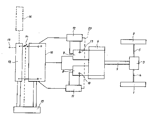
In this figure two rear wheels 1 and 2 of a vehicle are
shown, which rear wheels are driven by a differential 3 through
shafts 4 and 5. The differential 3 is driven itself by the gear box
6 through shaft 7. These electrica' DC-motors 8 and 9 are mechanic-
ally connected with the gear box 6. These motors can function in-
dependently. Upon turning on and off each motor will be coupled
and decoupled respectively with the gear wheels in the gear box 6.
,.. . , ~ : ~ ~ : ,. ,
2028493
s
Motors 8 and 9 are powered by the main stora~e battery 10
through electrical speed control means 11 and 12.
Apart from this mean storage battery 10 use is made according
to the present invention of a range extending device 13. This can
be a vegetable oil motor/generator but also a battery. This range
extending device 13 can be connected with the main storage battery
10 via switch 14 under the control of the battery charge system 15.
In case use is made of a range extending battery 13 this
battery can be charged from the mains at 17, but also for instance
from solar cells, when the vehicle is running.
At usually traffic speed in towns one of the motors 8 or 9
only is driving the vehicle, which is controlled by the electronic
speed control means 11 and 12. When, however, the vehicle speed
drops too much, for instance when driving up hill or when driving
off from traffic lights and accelerating, the two motors 8 and 9
will automatically be turned on in parallel by the electronic speed
control means 11 and 12. This parallel turn on action will be
mainly based on the motor load in combination with the accelerator
pedal position. As soon as the usual speed is reached, one of the
motors will be turned off again automatically. Which motor will be
turned off partly depends on the motor internal temperature which
is constantly measured by temperature sensitive means 18 and 19,
sensing the main winding temperature for instance. The temperature
senstive means control the electronic speed control means 11 and 12
in such a way that an electrical motor reaching a predetermined
high temperature, will be automatically turned off by the belonging
electronic speed control means. Above this predetermined maximum
temperature the motor efficiency starts to decrease too much be-
cause of increasing internal reslstance.
Therefore, during normal traffic one motor will be turned on
driving the vehic~le and the other motor turned off, so that it can
cool down. This will be reversed as soon as the driving motor
reaches the above predetermined high temperature. When this hot
motor will be turned off the other, cool motor, will be turned on
by the two electronic speed control means 11 and 12. To control
this alternating switching operation, each of the electronic speed
control means is under the control of the other speed control
,
- 2028~93
means, which is shown by the interrupted line 20. Also the acce-
lerator pedal (not shown) acts on the electronic speed control
means, but this pedal cannot influence which motor or whether all
motors will be turned on.
The motors 8 and 9 in general will receive their traction
current from the main traction battery 10 only. This main traction
battery 10 during normal operation will be trickle charged by the
range extending battery 13 via the battery charge control system
15, with switch 14 opened, as shown.
When upon driving the vehicle the voltage of the main battery
drops too much, for instance below 1,57 Volt per cell using a lead
acid battery, which is measured by the battery charge control
system 15, the range extending battery 13 will be connected in
parallel with the main traction battery by turning on switch 14.
The range extending battery now powers the motors 8 and/or 9.
Switch 14 will be opened anyhow and also trickle charging will be
stopped as soon as the cell voltage of the main traction battery 10
reaches 2,14 Volt, which is also under the control of the battery
charge control system 15.
~0 The range extending battery 13 can be charged in different
ways. In general by the mains 17 at a charging station, but also by
solar cell 16, which can be mounted on a vehicle. On a vessel a
wind generator could be used as well.