Note : Les descriptions sont présentées dans la langue officielle dans laquelle elles ont été soumises.
202874~
Back~ro~nd Of The Invention
This invention re:lates to auxiliary
electrical systems for internal combustion engines, and
more particularly to an alternator that is a source of
unidirectional current for charging a storage battery
or for operating other accessories.
The present invention is concerned with
engines that are used for powering machines such as
riding tractors, riding mowers and snowblowers. These
machines are often equipped with a storage battery for
engine s~arting and with headlights or other
accessories that are normally operated only when the
engine is running. The storage battery must be charged
with unidirectional current (half-wave or full-wave
rectified AC), but the other accessories can usually be
energized with alternating current.
The engine for such a machine typically has
an alternator that comprises one or more permanent
magnets carried for orbital motion by a rotatable
; 20 driven shaft of the engine, a magnetically cooperable
stator core mounted on the engine body adjacent to the
magnet orbit, and one or more sets of core windings in
which alternating current is induced due to the
movement of the magnets. Such an alternator has many
advantages over a DC generator, but when it is employed
to energize an electrical system that includes the
storage battery, the battery must be charged through a
rectifier.
If the alternator is used exclusively to
charge the storage battery, the alternator has a single
output of rectified current. A dual circuit or split
alternator having both alternating current and direct
current outputs may be used when direct current is
needed to charge the battery and alternating current is
needed to operate accessories such as headlights.
'' :~'~
~ 2- 202874~
The diode used to rectify the current that
charges the storage battery is typically located in an
output plug connected by one or more wires to the
alternator's stator. FIG. 1 hereto is an example of a
typical prior art plug. In FIG. 1, plug 10 is
connected to the stator (not shown) via lead wires 12
and 14. Lead wire 14 provides an alternating current
output via plug element 16. The output of plug element
18 is direct current which has been rectified by diode
20. Diode 20 is connected in series with lead wire 12
by a crimp connector 22. The other terminal of diode
20 i5 connected to plug element 18. A small diameter
tubing piece 24 made of a plastic heat shrinkable
material is heat shrunk around lead elements 12 and 14
and diode 20 to protect and insulate diode 20. A
second heat shrinkable tubing piece 26 surrounds tubing
piece 24 as well as the rear por~ion 28 of the plug.
It is apparent from the above description of
the plug depicted in FIG. 1 that the creation of the
prior art plug is a difficult and time-consuming task
since the plug contains a number of small parts and
since the diode must be well insulated. The insulation
requirement necessitates use of heat shrinkable tubing
and extra heating steps. The need for the heat
shrinkable tubing increases the cost of the plug, and
also makes it difficult to dissipate heat from the
diode. The heat shrunk tubing is not aesthetically
,pleasing.
Therefore, it is desirable to decrease the
manufacturing cost of alternator assemblies including
their output plugs, and to improve the heat dissipation
from the rectifier diode.
Summary Of The Invention
An alternator assembly for an internal
combustion engine is disclosed having a stator means
.~
i ~ ~
~3- 2~287~2
that includes at least one coil means. The coil means
cooperates with a moving magnetic field to produce an
output current in the coil rneans. ~ rectifier means
mounted on the stator means rectifies the output
current to yield direct current for charging a storage
battery.
In one embodiment/ the stator means comprises
a stationary annular ring member having an inner
~ surface and an outer surface. The coil means, which
i 10 may consist of a plurality of spaced wire coils, is
mounted circumferentially on the outer surface of the
stator means. A moving magnetic field is provided by a
plurality of rotating magnets, the magnets being
arranged in opposing relation to the wire coils and
concentric with them. The rotating magnets are
preferably mounted on an inner surface of a rotating
flywheel, so that the rotation of the flywheel induces
current flow in the coils. The output current is an
unregulated half-wave rectified direct current.
In another embodiment, the alternator
assembly has both alternating current and direct
current outputs. In this embodiment, the stator means
includes a first coil means and a second coil means.
The first coil means includes a first plurality of
spaced apart wire coils arranged circumferentially
about a first portion of the outer surface of the
stator's annular ring member. The second coil means
includes a second plurality of spaced wire coil means -
arranged circumferentially about a second portion of
the ring member's outer surface. Both pluralities of
coils cooperate with a moving magnetic field. The
first plurality of coils produces a first output
current ~hat is rectified by a rectifier means mounted
on the stator means. The second plurality of coils
35 produces a second output current, which is alternating ~ ~
.~- ""'' ."' .
_4_ Z028~
current, to energize accessories such as headlights.
Current is induced in both ~he first and second
pluralities of wire coils by a moving magnetic field
consisting of a plurality oE rotating magnets arranged
in opposing relation to the wire coils and concentric
with the coils. The rotating magnets are preferably
mounted on an inner surface of a rotating flywheel.
Since the rectifier means is mounted directly
on the stator means, forced air cooling from the
rotating flywheel helps dissipate heat from the
rectifier means. The mounting of the rectifier means
directly on the stator means also avoids the additional
cost of the heat shrink tubing on the output plug which
in prior art devices was necessary to insulate the
diode. The total savings achieved by the present
invention is about 2~ of the alternatorls manufacturing
cost. This savings is due to the elimination of the
heat shrinkable tubing for the plug and the heating
steps required to shrin~ the tubing. In addition, the
elimination of the heat shrink tubing make~ the output
plug more aesthetically pleasing.
It is a feature and advantage of the present
invention to facilitate heat dissipation in an
alternator assembly.
It is another feature and advantage of the
present invention to reduce the cost of an alternator
assembly ~hile making it more aesthetically pleasing.
These and other features and advantages of
the present invention will be apparent to those skilled
in the art from the following detailed description of
preferred embodiments and the attached drawings.
Brief Description Of The_Drawings
FIG. l is a side sectional view of a prior
art alternator output plug.
--5--
74~
FIG. 2 is a top plan view of a stator means
for an alternator assembly wherein the rectifier means
is located on the low or ground side of the stator.
FIG. 3 is a top plan view of a stator means
having a a single DC output, in which the rectifier
means is located on the output side of the stator
means.
FIG. 4 is a top plan view of a dual circuit
or split alternator stator having an alternating
.
~ - 10 current output and a direct current output, where the
; rectifier means is located on the ground side of the
direct current portion of the stator means.
FIG. 5 is a top plan view of a split
alternator stator similar to FIG. 4, except that the
rectifier means is located on the output side of the
direct current portion of the stator means.
Detailed Description Of Pref_rred Embodiments
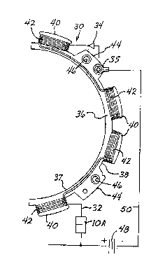
FIG. 2 depicts an alternator stator 30 having
a single unidirectional current output on line 32, and
wherein the single diode rectifier 34 has its anode
connected to ground at terminal 35.
In FIG. 2, a stationary annular ring member ~--
36 has an inner surface 37 and an outer surface 38.
Attached to the outer surface 38 is a plurality of
25 radially projecting pole teeth 40 arranged at -
substantially uniform intervals on the outer surface,
and a first plurality of first coil means 42. Each
coil in first coil means 42 is wound on its respective -~
pole teeth member 40.
Pole teeth 44 have no windings on them, but
instead have holes 46 through them to receive bolts
(not shown) or the like by which the stator can be -
secured to an engine body. .
A battery 48 has one terminal connected to ~-
ground terminal 35 via line 50 and its other terminal
connected to stator output line 32 via output plug lOA.
-6-
202~3742
Stator 30 is intended to be mounted on the
body of a small engine, adjacent to its rotating
flywheel and coaxial with the flywheel. Rotating
magnets (not shown) are mounted on an inner surface of
the rotating flywheel (not shown) and are arranged in
opposing relation to first coil means 42 and concentric
therewith. The rotating magnet creates a varying flux
that induces an alternating current in each of the
coils in first coil means 42. Rectifier 34 rectifies
this alternating current so that the output on output
line 32 is unregulated, half-wave rectified direct
current for charging storage battery 48.
The embodiment depicted in FIG. 3 is
identical to the one depicted in FIG. 2 except that
diode rectifier 34 is now located on the output side of
stator 30. FIGS. 2 and 3 illustrate that rectifier
means 34 may be located in any position as long as it
is connected in series with at least one of the coils
comprising first coil means 42.
In FIGS. 3-5, components having functions
corresponding to those of FIG. 2 have been given the
same numerical designations. The alternator assembly
depicted and described in connection with FIG. 3
operates in a similar manner to the one depicted in
FIG. 2.
FIGS. 4 and 5 depict another embodiment of
the present invention having a dual circuit or split
alternator configuration. Referring to FIG. 4, stator
52 comprises a stationary annular ring member 33 having
an inner surface 37 and an outer surface 38. A
plurality of pole teeth 40 project radially fro~ the
outer surface of annular ring member 33 and are
generally spaced evenly apart. Stator 52 is split into
a first portion and a second portion at lines 54. A
first coil means, consisting of a first plurality of
.,
~ -7
Z028741~
spaced wire coils 42, is arranged circumferentially
about the first portion of the outer surface of annular
ring member 33. Stator 52 also has a second coil means
consisting of a second plurality of spaced wire coils
56 arranged circumferentially about the second portion
of the outer surface of ann~lar ring member 33. Each
coil in the first and second pluralities of coils is
wound on its own pole teeth member 40. The second coil
means consisting of coils 56 is typically wound of a
~; 10 heavier gauge wire and has fewer turns than the first
coil means consisting of coils 42.
The alternating current induced in coils 56
is suitable to be applied directly to energize
headlights 58 via line 60. A switch 62 in the circuit
consisting of coils 56 and headlights 58 enables the
~ headlights to be turned on and off. Switch 62 for
: headlights 58 may be a double-throw switch with a
: central "OFF" position as depicted in FIGS. 4 and 5.
;: When switch 62 is in one ON position, headlights 58 are
20 energized by the second coil means via line 60. When ~ :
switch 62 is in its other ON position, headlights 58
are connected to storage battery 48 via line 68 so that :
:
~ headlights 58 may be energized by battery 48 when the
;~ engine is not running. Headlights 58 could be replaced
:~ 25 by another accessory for energization by the .
alternating current output from the second coil
means. Headlights 58 are grounded via line 64 at
ground terminal 66.
The first coil means consisting of coils 42 ~:
30 produce an alternating current which is rectified by :~
single diode rectifier 34. Diode 34 is mounted on ~ :
stator 52 by attaching its anode to ground terminal 35,
and its cathode to one of the coils 42.
The unregulated, half-wave rectified direct
35 current produced in the first coil means is output via :
~.",;
.: .:
~ 2028t74~
line 32 to charge storage battery 4~. One terminal of
battery 48 is grounded to ground terminal 35 via line
50.
The embodiments depicted in FIGS. 4 and 5
operate in a similar manner to the embodiments depicted
in FIGS. 1 and 2, except that the embodiments depicted
in FIGS. 4 and 5 produce both alternating and direct
current. In FIGS. 4 and 5, a moving magnetic field is
pr~vided by a plurality of rotating magnets (not shown)
mounted on an inner surface of a rotating flywheel (not
shown). The magnets are arranged in opposing relation
to the first and second pluralities of wire coils and
are concentric with the coils. The varying flux
induces an alternating current in both the first and
second pluralities of wire coils. The aIternating
current induced in the second plurality of wire coils
is output via line 60 and output plug 10B to energize
headlights 58 when switch 62 is in the appropriate ON
position. The alternating current induced in the first
plurality of wire coils, coils 42, is rectified by
rectifier means 34. The output from coils 42 is
unregulated, half-wave rectified direct current which
is output via line 32 and output plug 10B to charge
storage battery 48. In the embodiments depicted in
FIGS. 4 and 5, the DC current output is typically about
3 amps, while the AC output current is typically about
5 amps.
Rectifier diode 34 may be placed in any
position aIong the first portion of annular ring member
33 as lon~ as it is in series with one or more of coils
42. FIG. 5 depicts an embodiment similar to that of
FIG. 4 except diode 34 is now positioned near the
output of coils 42.
In the embodiments depicted in FIGS. 2 and 4,
the anode of diode 34 may be mounted to the stator's
, : , ~ . . ~ . -
'`: ' : ` : ` '' ' '
i'fi ~
2~ 87A2
steel laminations on the low or ~round side with a
terminal, or it may be soldered, or sonic or spot
welded. The cathode of diode 34 in that case may be
spliced or soldered to one of the coils 42.
If diode 34 is positioned on the output side
as depicted in FIGS. 3 and 5, the diode is mounted on
the stator with its anode connected to a coil 42 by
soldering or splicing, and its cathode is connected to
the output wire by soldering or splicing. The body of
the diode is attached to the stator with epoxy. If
diode 34 is positioned between two coils 42, it is
mounted to the stator by splicing or soldering its
anode to one coil 42, and splicing or soldering its
; cathode to another coil 42.
Several embodiments of the present invention
have been discussed above and are depicted in the
drawings. However, additional alternate embodiments
will be apparent to those skilled in the art and are
cor,templated as being within the scope of the present
invention. Therefore, the scope of the present
; invention is to be limited only by the following
claims. -
,', ~ '
." ,''~ ~
'..'',':'':
'''''~"'~ '
.: ~ ':