Note : Les descriptions sont présentées dans la langue officielle dans laquelle elles ont été soumises.
2028894
TUBULAR SILICON CARBIDE STRUCTURES
AND PROCESS FOR PRODUCTION THEREOF
BACKGROUND OF THE INVENTION
The present invention relates generally to tubular
structures such as water-jet nozzles for working articles
with water jets propelled at high velocity and to a
process for the production thereof. More particularly,
the invention relates to a silicon carbide tube to be
used particularly for a nozzle to eject water jet of the
abrasive type containing particles of abrasives such as
garnet and alumina admixed therein, and to a process for
producing the tube.
As is known, a water-jet working or machining
apparatus operates to eject water under high pressure
through a nozzle of small throat diameter thereby to
render the water into a jet of supersonic velocity and to
direct this jet against a workpiece material to work the
same. By this technique, almost any kind of material
such as plastics, papers, and metal alloys can be worked.
During this working or machining, there is almost no
scattering of dust or generation of heat, and three-
dimensional machining is also possible. In order to
further increase the precision and speed of the working
process, abrasive type water jets containing particles of
abrasives such as alumina and garnet are also being
developed.
The inner surface of the nozzle constituting the
flow path and orifice for discharging the water jet is
subject to severe abrasion and wear. Accordingly,
materials such as cemented carbide alloys, refractory
hard metals, and alumina ceramics are ordinarily being
used for these nozzles. There are also nozzles made of
sintered skeletons of cubic boron nitride as disclosed,
for example, in Japanese Utility Model Appln. Laid-Open
No. 63-50700 published April 6, 1988. These materials,
however, are of high price. Moreover, in the present
202889~
state of the art, these materials do not exhibit
durability to a degree commensurately expectable from the
intrinsic hardnesses of these materials.
Silicon carbide is a material next in hardness to
diamond and cubic boron nitride. Moreover its
precipitation by the vapor-phase synthesis method is
relatively easy. Therefore, silicon carbide is a
promising material for nozzles of the instant character.
Formed articles of silicon carbide of the prior art
have been produced by mixing various sintering aids such
as carbon, boron, and aluminum into a fine powder of
silicon carbide synthesized by the Acheson process, for
example, forming the mixture into the desired shape, and
then sintering the same. It has been found that, when
this material is used for a water-jet nozzle, it does not
exhibit a durability expectable from the intrinsic
hardness of silicon carbide. The cause of this
disappointing result is considered to be that, because
the sintering aids wear away priorly, or the bonding with
the sintering aids is insufficient, the particles of
silicon carbide become free and drop off, whereby the
intrinsic hardness of silicon carbide cannot be amply
utilized.
Another problem encountered hitherto has been the
severe requirement for precision of shape because of the
minute inner diameter of a water-jet nozzle of the order
of 1 mm. For this reason, the forming of a water-jet
nozzle from sintered silicon carbide has been thought to
be difficult.
We have made a study of chemical vapor-phase
synthesis processes with the view of providing a process
for obtaining immediately in a desired shape a silicon
carbide of high purity containing no sintering aids. As
a result, we have found that a nozzle produced by such a
process has a performance superior to that of a
conventional sintered silicon carbide product. We have
thus arrived at the present invention.
20288 94
-
SUMMARY OF THE INVENTION
According to thls lnventlon there ls provlded a
process for produclng a water-~et nozzle for use ln machlnlng
artlcles wlth an abraslve water-~et propelled therethrough,
comprlslng the steps of: machlnlng an outer surface of a
cyllndrlcal rod-shaped graphlte structure, so that lt has an
outer surface portlon correspondlng ln dlmenslon exactly to an
lnternal hole of the water-~et nozzle to be produced;
deposltlng hlgh-denslty and hlgh-purlty slllcon carblde on the
outer surface of the graphlte structure by a vapor-phase
synthesls method, so that the slllcon carblde forms a
cyllndrlcal tubular structure on the graphlte structure, the
tubular structure havlng a denslty of from 3.18 to 3.21 g/cm3
and a maxlmum lmpurlty content of 20 ppm; thereafter heatlng
the graphite structure together wlth sald tubular structure ln
alr to oxldlze the graphlte structure to leave only sald
tubular structure; and flxedly securlng an enveloplng outer
metal or metal alloy cyllnder to an outer surface of sald
tubular structure, thereby obtalning the water-~et nozzle
havlng an lnternal hole of hlgh preclslon and hlgh durablllty
to abraslon and wear.
The nature, utlllty, and further features of thls
lnventlon wlll be more clearly apparent from the followlng
detalled descrlptlon lncludlng that of preferred embodlments
of the lnventlon when read ln con~unctlon wlth the
accompanylng drawlng.
BRIEF DESCRIPTION OF THE DRAWING
Flgure 1 ls a slde vlew, ln longltudlnal sectlon, of
a nozzle ln whlch a slllcon carblde tube made by the method of
-- 3
20375-676
';, '"
~- 202889~
thls lnventlon ls used;
Flgures 2 through 6 are slmllar vlews respectlvely
lllustratlng other modes of practlce of the lnventlon; and
Flgure 7 ls a vlew explanatory of the process
accordlng to thls lnventlon.
DESCRIPTION OF THE ~ EMBODIMENTS
The hlgher the denslty of the tube materlal, the
more deslrable lt ls. That of the tube of thls lnventlon ls
3.18 g/cm or hlgher. The upper llmlt of thls denslty can be
made almost equal to the theoretlcal denslty of 3.21 g/cm3.
Moreover, the resultlng materlal ls almost fully lmpervlous to
gases.
The slllcon carblde tubes of thls lnventlon can be
of varlous forms as lllustrated by only a few examples ln the
accompanylng drawlng. Sultable dlmenslons of the tubes when
they are used as nozzles are wlthln ranges of
- 3a -
20375-676
, ' ''
2~2889~
outer diameter of 1 to 10 mm and of inner diameter of 0.1
to 4.8 mm.
These tubes are produced in the following manner.
It is not possible to fabricate a tube of this
invention by sintering by using a powder of silicon
carbide. The tube can be made by chemical vapor-phase
synthesis.
For preparing silicon carbide by a chemical vapor-
phase synthesis process, a substance to become the base
material is necessary. In the practice of this
invention, for fabricating silicon carbide in the form of
a nozzle, a base material of the shape of a cylindrical
rod of a specific diameter is used. The substance is
graphite. Particularly in the case where impurities are
to be avoided, refined graphite is used. Each rod is
fabricated to a length conforming to the length of the
water-jet nozzle. Then, silicon carbide is deposited
onto the base material by evaporation by a chemical
vapor-phase method. In this connection, the thermal
expansion coefficient of the silicon graphite to be
evaporation deposited is approximately 4.5 x 10⁻⁶ l/C.
For this reason, a graphite of a thermal expansion
coefficient of from 4.5 x 10⁻⁶ to 5.0 x 10⁻⁶ l/C was
used for the base material.
As the chemical vapor-phase method, any suitable
known method may be used. One example of such a method
is that in which a silane hydrocarbon such as
methyltrichlorosilane and hydrogen gas are used. Another
example is a method in which a silane gas and a
hydrocarbon gas diluted with hydrogen gas are used.
Still another example is a method in which SiO gas and CO
gas which are generated from SiO2 and carbon (graphite)
are used.
By such a chemical vapor-phase method, a graphite
base material of rod shape covered with silicon carbide
to a specific coating thickness is obtained. By cutting
this base material to a specific length and removing the
202889 1
graphite base material by an oxidation method in air, a
tube of silicon carbide of a specific desired shape can
be fabricated. The tube thus fabricated can be used by
any of various methods. One is the method of brazing or
bonding the tube to the inner surface of an ultrahard
nozzle. Another is the method of depositing silicon
carbide to a great thickness and using the tube directly
as it is.
By a chemical vapor-phase synthesis process as
described above, a polycrystalline silicon carbide of
high purity not containing any sintering aid is obtained.
Moreover, since the polycrystalline particles are finely
bonded, the product has a high density and is impervious
to fluids. When this is used as a water-jet nozzle, its
resistance to abrasive wear is remarkably improved.
Examples
By machining a workpiece of isotropic graphite, a
round rod G (FIG. 7) of graphite of a diameter of 1.8 mm
and a length of 45 mm was obtained. This round rod G as
a base material was heated at 1,700C in a gaseous
atmosphere of SiO and CO gases thereby to precipitate a
polycrystalline film la of silicon carbide of a film
thickness of 2 mm on the surface of the round rod G.
The silicon carbide film la thus deposited on the
end faces of the round rod G was scraped off as indicated
at lb in FIG. 7. The rod G together with the film la was
then heated at 800C in air, whereupon the rod G is
burned and removed and a silicon carbide tube of an inner
diameter of 1.8 mm, a wall thickness of 2 mm, and a
length of 40 mm was obtained.
The thus obtained tube had a density of 3.21 g/cm3
and an impurity content of 5 ppm and was almost
completely impervious to gases.
By this method, various tubes as described below
were fabricated and used as nozzles.
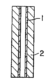
A general side view in longitudinal section of a
nozzle in which the above described tube is used is shown
20Z8~94
in FIG. 1. This structure comprises the tube 1 and an
outer cylinder 2 enveloping the tube 1 for protecting and
reinforcing the same. This example illustrates the case
where an inner cylinder, consisting of silicon carbide
tube 1 of circular cross section having a constant
diameter in its longitudinal direction, is fixed
integrally to the interior wall surface of an outer
cylinder 2 made of a metal or an ultrahard metal alloy.
This fixing between the inner and outer cylinders is
carried out by a method such as brazing or bonding.
However, in the case where the outer diameter of the tube
is large, shrinkage fitting is also possible.
In the operation of the nozzle of the above
described construction, an ultrahigh-velocity jet of
lS water containing abrasive particles therein passes
through the ejection orifice formed by the tube. The
inner wall of this ejection orifice is formed from a
polycrystalline silicon carbide of excellent resistance
against abrasive wear. Therefore the rate of its wear is
low, whereby the tube can withstand use over a long
service period.
In another preferred mode of practice of this
invention as shown in FIG. 2, the inner diameter of the
polycrystalline silicon carbide tube 1 varies linearly at
a constant rate in a tapering manner in the longitudinal
direction, decreasing toward the discharge end at the
bottom as viewed in the figure. The tube 1 and the outer
cylinder 2 are fixedly joined by the same method as in
the first example.
In still another mode of practice of this invention
as illustrated in FIG. 3, the inner diameter of the
silicon carbide tube 1 varies continuously in the
longitudinal direction, whereby the contour of each side
of the tube 1 as viewed in the sectional view of FIG. 3
is a continuous fair curve. The tube 1 and the outer
cylinder 2 are fixedly joined in the same manner as in
the preceding examples.
20Z889~
_
In still another mode of practice of this invention
as shown in FIG. 4, the silicon carbide tube 1 is funnel
shaped at the entrance end thereof. The tube 1 and the
outer cylinder 2 are fixedly joined in the same manner as
in the preceding examples.
FIG. 5 illustrates one example of a further mode of
practice of this invention in which a polycrystalline
silicon carbide tube 1 is a homogeneous unit structure of
a thick wall constituting a nozzle without an outer
cylinder 2. In this case where the wall of the tube 1 is
thick, the tube can be used without the outer cylinder 2
to function as a reinforcing part. Furthermore, it is
also possible to machine (grind) the tapered funnel-
shaped entrance after the tube 1 has been formed.
Depending on the necessity, the outer cylindrical surface
can also be processed.
In a further mode of practice of this invention as
shown in FIG. 6, the tube 1 is reinforced by an outer
cylinder 3 which is a sintered metal structure. The
polycrystalline silicon carbide tube 1 and the outer
cylinder 3 are sintered together to form an integral
structure. In this example, the inner diameter of the
tube 1 varies continuously, contracting in the downward
direction from the entrance to a constricted throat
portion and then expanding toward the discharge orifice.
The contour of this tube 1 as viewed in the longitudinal
section of FIG. 6 comprises two continuous fair curves in
symmetrical opposition.
In the above described examples, the present
invention has been described with respect to wear
resistant structures made of silicon carbide prepared by
vapor-phase synthesis and adapted for use as nozzles for
ejecting ultrahigh-velocity jets containing abrasives and
passing therethrough. However, the invention is not
limited to such application. It will be obvious, of
course, that the tube of the invention can be applied
with equally good results to ejection nozzles for
2028894
-
discharging jets of ultrahigh-pressure fluids or high-
pressure fluids in which no abrasives have been admixed.
Furthermore, with respect to the above described
examples of modes of practice and other possible modes,
various modifications and alternative combinations are
possible in features such as the shapes of the inner wall
surfaces of the tubes in longitudinal section and in
cross section, the external shape, and the method of
joining of the inner tube and the outer cylinder. It is
to be understood that all such modifications and
alternative arrangements are intended to be within the
purview of this invention.
As described above, a polycrystalline silicon
carbide tube according to this invention can be used as a
structure constituting an inner wall surface in the
fabrication of a nozzle for ejecting a fluid under high
pressure. For this reason, the diameter of the high-
velocity jet ejected from the nozzle remains stable over
a long period. Accordingly the frequency of replacement
of the nozzle is decreased, and the work efficiency and
material working precision are greatly improved.