Sélection de la langue

Search

Sommaire du brevet 2029422 

Énoncé de désistement de responsabilité concernant l'information provenant de tiers

Une partie des informations de ce site Web a été fournie par des sources externes. Le gouvernement du Canada n'assume aucune responsabilité concernant la précision, l'actualité ou la fiabilité des informations fournies par les sources externes. Les utilisateurs qui désirent employer cette information devraient consulter directement la source des informations. Le contenu fourni par les sources externes n'est pas assujetti aux exigences sur les langues officielles, la protection des renseignements personnels et l'accessibilité.

Disponibilité de l'Abrégé et des Revendications

L'apparition de différences dans le texte et l'image des Revendications et de l'Abrégé dépend du moment auquel le document est publié. Les textes des Revendications et de l'Abrégé sont affichés :

  • lorsque la demande peut être examinée par le public;
  • lorsque le brevet est émis (délivrance).
(12) Brevet: (11) CA 2029422
(54) Titre français: DISPOSITIF DE DONNEES SUR LA CHARGE D'UN ASCENSEUR ET METHODE CONNEXE
(54) Titre anglais: PROCEDURE AND APPARATUS FOR PRODUCING ELEVATOR LOAD DATA
Statut: Périmé et au-delà du délai pour l’annulation
Données bibliographiques
(51) Classification internationale des brevets (CIB):
  • B66B 1/34 (2006.01)
(72) Inventeurs :
  • TORENIUS, PEKKA (Finlande)
  • MALLINEN, HEIKKI (Finlande)
(73) Titulaires :
  • KONE ELEVATOR GMBH
(71) Demandeurs :
  • PEKKA TORENIUS (Finlande)
  • HEIKKI MALLINEN (Finlande)
(74) Agent: G. RONALD BELL & ASSOCIATES
(74) Co-agent:
(45) Délivré: 1998-12-29
(22) Date de dépôt: 1990-11-07
(41) Mise à la disponibilité du public: 1991-05-11
Requête d'examen: 1995-06-14
Licence disponible: S.O.
Cédé au domaine public: S.O.
(25) Langue des documents déposés: Anglais

Traité de coopération en matière de brevets (PCT): Non

(30) Données de priorité de la demande:
Numéro de la demande Pays / territoire Date
895376 (Finlande) 1989-11-10

Abrégés

Abrégé français

Cette invention concerne une procédure et un appareil de production de données sur la charge d'un ascenseur. La procédure fait appel à un ou plusieurs détecteurs de tension placés sur la cabine d'ascenseur ou sur un élément supportant le poids de celle-ci. Au moins un détecteur est placé sur la cabine d'ascenseur à un endroit où la tension exercée par la charge est élevée. D'après les informations fournies par les détecteurs, l'appareil produit un signal de charge de cabine et un autre signal de charge utilisés pour régler le démarrage du moteur de levage en fonction de la position de la cabine d'ascenseur.


Abrégé anglais


Procedure and apparatus for producing elevator
load data. The procedure employs one or more tension
sensing detectors placed on the elevator car unit or on a
member carrying the weight of said unit. At least one
detector is placed on the elevator car unit in a location
where the tension caused by the load is high. Based on the
information obtained from the detectors, a car load signal
and another load signal, used especially in the start
setting of a hoisting motor drive and dependent on the
position of the elevator car unit, are produced.

Revendications

Note : Les revendications sont présentées dans la langue officielle dans laquelle elles ont été soumises.


THE EMBODIMENTS OF THE INVENTION IN WHICH AN EXCLUSIVE
PROPERTY OR PRIVILEGE IS CLAIMED ARE DEFINED AS FOLLOWS:
1. A method for producing load data of an
elevator, comprising the steps of:
detecting load data of the elevator by using
tension-sensing detectors placed on an elevator car unit or
on a member carrying the weight of the unit, wherein at
least one of the detectors is placed on the elevator car
unit in a location where the tension caused by the load is
high;
producing a car load signal based on information
from the detectors;
producing a further load signal based on the
information from the detectors, the further load signal
being dependent on the position of the elevator car unit;
and,
using the further load signal in start-setting of
a hoisting motor drive.
2. A method according to claim 1, wherein the at
least one detector is placed at the same height with the
fixing point of a lifting member or members or at least
close to it.
3. A method according to claim 1 or 2, wherein
at least one compensation detector is placed on a balancing
means comprised in the elevator car unit.
4. A method according to claim 3, wherein the
detector placed on the balancing means is used to produce a
signal representing the position of the elevator car unit.
5. An apparatus for applying the method of claim
1, comprising:

one or more tension-sensing detectors placed on
the elevator car unit or on the member carrying the weight
of the unit; and,
an amplifier unit placed on the elevator car unit
or on the member carrying the weight of the unit;
wherein at least one of the detectors is placed on the
elevator car unit in a location where the tension caused by
the load is high, wherein based on information from the
detectors a car load signal is produced, and wherein based
on the information from the detectors a further load signal
is produced which is dependent on the position of the
elevator car unit, the further load signal being used in
start-setting of a hoisting motor drive.
6. An apparatus according to claim 5, further
comprising at least one compensation detector placed on a
balancing means comprised in the elevator car unit, said
compensating detector serving to produce a signal indicating
the position of the elevator car unit.
7. An apparatus according to claim 5 or 6, for
producing elevator load data in the case of an elevator
provided with hoisting ropes, wherein at least one detector
is placed on a structure in the upper part of the elevator
car unit.
8. An apparatus according to claim 5 or 6, for
producing elevator load data for use in a hydraulic
elevator, wherein at least one detector is placed on a
supporting member serving to move the elevator car unit, or
on a beam supporting the elevator car unit.
9. An apparatus according to any one of claims
5 to 8, wherein each of the tension-sensing detectors is
independently connectable to the amplifier unit, and is
attached to the elevator car unit or the member carrying the
weight of the unit by mechanical means.

Description

Note : Les descriptions sont présentées dans la langue officielle dans laquelle elles ont été soumises.

2 ~ 2 2
The present invention relates to a procedure and
an apparatus for producing load data in an elevator, said
procedure employing one or more tension sensing detectors
placed in an elevator car unit or on a member supporting the
weight of an elevator car unit.
In conventional elevator load measuring systems,
the purpose is to obtain signals dependent on the load of
the elevator car. A load measuring instrument of this type,
designed for an elevator car using hoisting ropes, is
proposed e.g. in Patent Publication FI 75048. In the
elevator described in this publication, the bottom of the
elevator car rests on isolating elements resting on the
horizontal shoulders of angle irons whose vertical shoulders
are secured with screws on the bottom frame. Attached above
and below each angle iron is a strain gauge. According to
the publication mentioned, it is preferable to use four
angle irons placed at the four corners of the bottom frame.
One of the drawbacks of the solution proposed in this
publication is that the strain gauges are difficult to
mount, especially if they should be mounted after elevator
installation.
Conventional load measuring systems fitted under
the elevator car can not provide start setting data
directly. Instead, a separate load-weighing device, e.g. a
brake scale is needed for this purpose.
The object of the present invention is to
eliminate the above-mentioned drawbacks and to provide a
system for generating elevator load data for use in the
modernization of elevators.
The procedure of the invention for producing
elevator load data is characterized in that at least one
detector is placed on the elevator car unit in a location
where the tension caused by the load is high, and that,
based on the information obtained from the detectors, a car
load signal and a car position signal, used especially in

2029422
the start setting of a hoisting motor drive, dependent on
the position of the elevator car unit, are produced.
The apparatus of the present invention can be
easily adapted to existing elevators. Compared to a load
weighing device placed under the elevator car, the invention
provides significant advantages in the modernization of
elevators. The elevator car does not need to be lifted for
mounting the detectors and therefore no extra space is
necessary below the overhead beam of the car frame.
Furthermore, no additional insulating elements and
constructional changes under the elevator car are required,
as in the case when the load measuring system is placed
under the elevator car. Moreover, the apparatus can be used
in elevator car-frame systems where no insulation is
provided between the elevator car and the car frame.
In the following, the invention is described in
detail by the aid of examples with reference to the attached
drawings, in which:
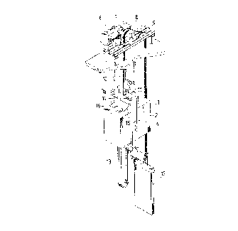
Figure 1 illustrates an elevator system provided
with a load measuring apparatus according to the present
invention;
Figure 2 illustrates a perspective view of the
load measuring apparatus of the present invention;
Figure 3 shows a perspective view of a preferred
embodiment of an elevator car unit provided with a load
measuring apparatus according to the invention;
Figure 4 shows a perspective view of another
embodiment of an elevator car unit provided with a load
measuring apparatus according to the present invention;
Figure 5 shows a perspective view of yet another
embodiment of an elevator car unit provided with a load
measuring apparatus according to the present invention;
Figure 6 illustrates the block diagram of the
apparatus of the invention;

Figures 7a - 7d illustrate the variation of the
outputs of the amplifiers with the position on the car
floor;
Figures 8a - 8b show a hydraulic elevator
provided with a load measuring apparatus according to the
present invention.
The elevator system illustrated in Figure
comprises an elevator car unit 1 consisting of an elevator
car 2 and a car frame, said unit moving along guide rails in
a hoistway (not shown). The car frame consists of overhead
beams 3a and 3b, side beams 4 and bottom beams 5a and 5b.
The elevator car unit is moved using hoisting ropes 10
operated by a hoisting motor 6, transmission unit 7,
traction sheave 8 and diverting pulley 9 placed in a machine
room above the hoistway. The hoisting motor is provided
with a control unit. One end of the hoisting ropes is
attached to a fixing point 11 located between the overhead
beams and the other end of the ropes is attached to a
counterweight 12. A car cable 13 is connected to the
elevator car unit. In this embodiment a vertical (side)
beam 4 secures at its upper end the ends of both overhead
beams. The car is comprised inside the car frame.
For measuring the car load by the procedure of
the invention, a strain gauge transducer 14 is placed on top
of the overhead beam 3a and is connected via a cable 15 to
a central unit 16 mounted on top of the elevator car.
The load measuring apparatus illustrated in
Figure 2 comprises the strain gauge transducer 14, the
connecting cable 15 and an amplifier card 17 placed in a
housing 18 provided with a lead-through 19. If d.c. supply
is not available and a mains supply voltage for relay
outputs is needed, an adapter card 20 is also included in
housing 18. The detector 14 may be e.g. a strain gauge
transducer as proposed in Patent Publication FI 62904. This
transducer, when attached by its ends with screws to an
adequate base, senses the tensile and compressive stresses
;~
. ..

of the base in the longitudinal direction of the transducer.
Attached between the ends of the body of the transducer are
strain gauges which bend at their fixing points due to the
tensile and compressive stresses of the base.
Figure 3 shows an embodiment of an elevator car
unit in which the overhead beams are attached to separate
vertical beam 2la and 2lb, respectively or the elevator car
2 is mounted in an asymmetrical position relative to the car
frame. In this case, two detectors (14 and 22) are used,
one on each overhead beam. The detectors are connected to
the central unit via cables 15 and 23.
The detectors produce signals indicating the
force (load) applied to the hoisting ropes. In addition, it
is possible to obtain signals indicating changes in beam
tension caused by installation errors or by the guides of
the elevator car. This makes it possible to determine the
quality of the installation as well as the kinetic friction
of the elevator car system.
Figure 4 shows an elevator car unit similar to
the unit shown in Fig. 1, with a hoisting rope pulley 24
mounted in the overhead beam. In addition, the unit is
provided with balancing means, which is attached to the
bottom beam and consists of a beam 25 and a balancing chain
26 or the like. The elevator car is mounted in a
symmetrical position relative to the car frame. In this
case, beam 25 is provided with a detector 27, connected to
the central unit via cable 28. The system is proposed to
check the balancing of the elevator system.
Figure 5 shows an elevator car unit similar to
that in Figure 3. In this case, the overhead beams are
attached to separate vertical beams and/or the car is in an
asymmetrical position relative to the car frame. As in the
case of Figure 4, the elevator car unit is provided with a
rope pulley and the balancing means is attached to the
bottom beam. In addition, the unit has a compensation
detector 27 providing absolute car position data.
A

2029422
Fig. 6 shows a block diagram of the apparatus of
the invention. As shown in Fig. 2, the central unit 16
comprises an amplifier card 17. The amplifier is fed by a
24V d.c. voltage Vdc. The amplifier card is connected via
conductors to three detectors (detector 1, detector 2 and
detector 3) 14, 22 and 27 and has transistor outputs
connected to the control panel. The conductors can also be
replaced by a bus. If d.c. supply Vdc is not available and
potential-free contactors are needed, an adapter card 20
converting the mains voltage Vac into a d.c. voltage is used
in connection with the central unit. In addition, the
apparatus may have relay outputs R connected to the control
panel.
Figure 7a shows the amplified output 01 of a load
measuring channel(s). It shows an output LF for a fully
loaded elevator car and an output LE for an empty car. The
output 01 increases linearly from the lowest floor A to the
highest floor Y (horizontal axis) of the elevator car, due
to the position dependent load caused by the car cable and
the balancing means. The difference between outputs LF and
LE represents the load L. In addition, Figure 7a shows a
constant output (offset) OS representing the load imposed by
the weight of the elevator car unit itself. Figure 7b shows
the compensation channel output 02, which is a linearly
rising signal BT representing the load caused by the
balancing means and the car cable. Figure 7c shows the load
signal L, which is obtained by subtracting the offset OS and
the weight of the elevator car unit, hoisting ropes and
balancing means from the output 01 of Figure 7a. Figure 7d
represents the linearly changing start setting data ST with
incorrect or missing compensation. The difference between
the middle value and the zero level observed at the start
represents the compensation error OS'.
Figure 8a illustrates the apparatus of the
invention as applied in the case of a hydraulic elevator
using a hydraulic lifting cylinder 29 for moving an elevator

2029~2~
car unit 36. The hydraulic system comprises a movable
piston 30 inside the cylinder 29, a pressure pipe 31 and a
lifting machine 32. The latter consists of a hydraulic
pump, a lifting motor and other equipment required for the
lifting. The piston is connected to the elevator car unit
via an arm 33. A car cable 34 is attached to the bottom of
the car unit. On the supporting beam 35 of the lifting
cylinder, a detector 14, a central unit 16 and a connecting
cable 15 are installed. In the case of Figure 8b, the load
measuring apparatus is placed on the arm 33 near the
elevator car unit.
It is obvious to a person skilled in the art that
different embodiments of the invention are not restricted to
the examples described above, but that they may instead be
varied within the scope of the following claims. Instead of
strain gauge transducers it is possible to use e.g.
piezoelectric or other tension sensing detectors.

Dessin représentatif
Une figure unique qui représente un dessin illustrant l'invention.
États administratifs

2024-08-01 : Dans le cadre de la transition vers les Brevets de nouvelle génération (BNG), la base de données sur les brevets canadiens (BDBC) contient désormais un Historique d'événement plus détaillé, qui reproduit le Journal des événements de notre nouvelle solution interne.

Veuillez noter que les événements débutant par « Inactive : » se réfèrent à des événements qui ne sont plus utilisés dans notre nouvelle solution interne.

Pour une meilleure compréhension de l'état de la demande ou brevet qui figure sur cette page, la rubrique Mise en garde , et les descriptions de Brevet , Historique d'événement , Taxes périodiques et Historique des paiements devraient être consultées.

Historique d'événement

Description Date
Le délai pour l'annulation est expiré 2003-11-07
Lettre envoyée 2002-11-07
Accordé par délivrance 1998-12-29
Préoctroi 1998-08-18
Inactive : Taxe finale reçue 1998-08-18
Un avis d'acceptation est envoyé 1998-02-25
Lettre envoyée 1998-02-25
Un avis d'acceptation est envoyé 1998-02-25
Inactive : Renseign. sur l'état - Complets dès date d'ent. journ. 1998-02-20
Inactive : Dem. traitée sur TS dès date d'ent. journal 1998-02-20
Inactive : CIB attribuée 1998-02-12
Inactive : CIB enlevée 1998-02-12
Inactive : CIB en 1re position 1998-02-12
Inactive : Approuvée aux fins d'acceptation (AFA) 1998-02-03
Exigences pour une requête d'examen - jugée conforme 1995-06-14
Toutes les exigences pour l'examen - jugée conforme 1995-06-14
Demande publiée (accessible au public) 1991-05-11

Historique d'abandonnement

Il n'y a pas d'historique d'abandonnement

Taxes périodiques

Le dernier paiement a été reçu le 

Avis : Si le paiement en totalité n'a pas été reçu au plus tard à la date indiquée, une taxe supplémentaire peut être imposée, soit une des taxes suivantes :

  • taxe de rétablissement ;
  • taxe pour paiement en souffrance ; ou
  • taxe additionnelle pour le renversement d'une péremption réputée.

Veuillez vous référer à la page web des taxes sur les brevets de l'OPIC pour voir tous les montants actuels des taxes.

Historique des taxes

Type de taxes Anniversaire Échéance Date payée
Requête d'examen - générale 1995-06-14
TM (demande, 7e anniv.) - générale 07 1997-11-07 1997-10-23
Taxe finale - générale 1998-08-18
TM (demande, 8e anniv.) - générale 08 1998-11-09 1998-10-30
TM (brevet, 9e anniv.) - générale 1999-11-08 1999-10-13
TM (brevet, 10e anniv.) - générale 2000-11-07 2000-10-11
TM (brevet, 11e anniv.) - générale 2001-11-07 2001-10-15
TM (demande, 2e anniv.) - générale 02 1992-11-09
Titulaires au dossier

Les titulaires actuels et antérieures au dossier sont affichés en ordre alphabétique.

Titulaires actuels au dossier
KONE ELEVATOR GMBH
Titulaires antérieures au dossier
HEIKKI MALLINEN
PEKKA TORENIUS
Les propriétaires antérieurs qui ne figurent pas dans la liste des « Propriétaires au dossier » apparaîtront dans d'autres documents au dossier.
Documents

Pour visionner les fichiers sélectionnés, entrer le code reCAPTCHA :


Pour visualiser une image, cliquer sur un lien dans la colonne description du document. Pour télécharger l'image (les images), cliquer l'une ou plusieurs cases à cocher dans la première colonne et ensuite cliquer sur le bouton "Télécharger sélection en format PDF (archive Zip)" ou le bouton "Télécharger sélection (en un fichier PDF fusionné)".

Liste des documents de brevet publiés et non publiés sur la BDBC .

Si vous avez des difficultés à accéder au contenu, veuillez communiquer avec le Centre de services à la clientèle au 1-866-997-1936, ou envoyer un courriel au Centre de service à la clientèle de l'OPIC.


Description du
Document 
Date
(aaaa-mm-jj) 
Nombre de pages   Taille de l'image (Ko) 
Page couverture 1993-12-04 1 14
Abrégé 1993-12-04 1 17
Revendications 1993-12-04 2 68
Description 1993-12-04 6 253
Dessins 1993-12-04 5 114
Description 1997-12-24 6 273
Revendications 1997-12-24 2 80
Page couverture 1998-12-21 1 45
Dessin représentatif 1998-12-21 1 10
Avis du commissaire - Demande jugée acceptable 1998-02-25 1 165
Avis concernant la taxe de maintien 2002-12-05 1 173
Taxes 1998-10-30 1 45
Correspondance 1998-08-18 1 34
Taxes 1997-10-23 1 52
Taxes 1994-11-04 1 47
Taxes 1996-10-30 1 57
Taxes 1995-11-06 1 47
Taxes 1993-11-05 1 40
Taxes 1992-11-05 1 39
Correspondance de la poursuite 1995-06-14 1 50
Correspondance de la poursuite 1997-11-03 1 26
Demande de l'examinateur 1997-10-21 1 25
Correspondance de la poursuite 1997-06-16 5 166
Demande de l'examinateur 1997-04-02 2 75
Courtoisie - Lettre du bureau 1995-08-21 1 36