Sélection de la langue

Search

Sommaire du brevet 2029847 

Énoncé de désistement de responsabilité concernant l'information provenant de tiers

Une partie des informations de ce site Web a été fournie par des sources externes. Le gouvernement du Canada n'assume aucune responsabilité concernant la précision, l'actualité ou la fiabilité des informations fournies par les sources externes. Les utilisateurs qui désirent employer cette information devraient consulter directement la source des informations. Le contenu fourni par les sources externes n'est pas assujetti aux exigences sur les langues officielles, la protection des renseignements personnels et l'accessibilité.

Disponibilité de l'Abrégé et des Revendications

L'apparition de différences dans le texte et l'image des Revendications et de l'Abrégé dépend du moment auquel le document est publié. Les textes des Revendications et de l'Abrégé sont affichés :

  • lorsque la demande peut être examinée par le public;
  • lorsque le brevet est émis (délivrance).
(12) Demande de brevet: (11) CA 2029847
(54) Titre français: CHAUFFE-MORTIER
(54) Titre anglais: HEATER FOR A MORTAR PREPARATION SYSTEM
Statut: Réputée abandonnée et au-delà du délai pour le rétablissement - en attente de la réponse à l’avis de communication rejetée
Données bibliographiques
Abrégés

Abrégé anglais


ABSTRACT
This invention describes a heating system for use with a
mortar mixing unit. The heating system is comprised of a
series of heat exchanging portions used to inhibit freezing of
the materials used to prepare mortar in extremely cold weather
conditions. The first heat exchanging portion is used to heat
the water used to mix mortar. The second heat exchanging
portion is used to warm the mixing unit, which contains the
water, aggregate, and sand. The third heat exchanging portion
is used to warm the aggregate, which is contained in a silo.

Revendications

Note : Les revendications sont présentées dans la langue officielle dans laquelle elles ont été soumises.


Claims:
1. A heating system for use with a mortar mixing unit
which comprises a silo means for holding an aggregate and a
binder; a water supply means; and a mixing unit connected to
said silo means and said water supply means for mixing said
aggregate, said binder and said water to produce said mortar;
said heating system comprising:
(a) heat energy producing means for producing a supply of
heat energy wherein said heat energy is comprised of products
of combustion and air;
(b) a water reservoir means connected between said water
supply means and said mixing unit; and
(c) a heating tube means having a first end, a second
end, and a heat exchanging portion located within said water
reservoir means, said first end being connected to said heat
energy producing means for conducting said heat energy into
said heat exchanging portion, said second end forming an
exhaust port; wherein water supplied to said mixing means is
heated prior to mixing.
2. The heating system of claim 1 further comprising a
second heat exchanging portion of said heating tube means
between said silo and said mixing unit, wherein said second
heat exchanging portion heats said binder, said aggregate and
said water in said mixing unit.

3. The heating system of claim 1 or 2 further comprising
an additional heat exchanging portion which is contained in
said aggregate between said first end and said second end of
said heating tube means, wherein said additional heat
exchanging portion heats said aggregate.
4. The heating system of claim 1 wherein said heat
energy producing means is a gas burner.
5. The heating system of claim 4 wherein said gas burner
is a propane gas burner.
6. The heating system of claim 1 wherein the temperature
of said heat energy at said second end of said heating tube
means is sufficiently high to inhibit said products of
combustion from producing a condensate in said silo means.

Description

Note : Les descriptions sont présentées dans la langue officielle dans laquelle elles ont été soumises.

~2~
Heater for a Mortar Preparation Svstem
Field of the Invention
The present invention relates to an apparatus for heating
materials required to produce mortar. More particularly, the
present invention relates to the use of a high pressure burner
used to control the temperature of the materials used in the
mortar mixing process to inhibit freezing.
Backqround of the Invention
Current mortar mixing apparatus do not function properly
in cold weather. The mixing process typically involves
combining an aggregate and a binder with water in such a
fashion that the desired mixing ratio is obtained.
In extremely cold weather the aggregate, for example
sand, may freeze due to the significant moisture content in
the sand. The water used in the mixing process is also very
susceptible to freezing. The binder, for example cement, is
very dry and of relatively small volume and does not tend to
~0 become frozen in very cold conditions.
The mixing process is severely inhibited when the sand or
water become frozen. As a result, the preparation of mortar
becomes very difficult, if not impossible, in extremely cold
weather.
Prior Art
Prior art techniques employed to operate a mortar
preparation apparatus in cold weather have been restricted to

2~2~
small inef~ective electric heating cables and elements, which
do not operate properly in very cold weather.
Prior art techniques have also involved using tarpaulins
to cover ~he entire mixing and silo portions o~ the apparatus.
This method is not sufficient in extremely cold weather,
because the tarpaulin merely acts as an insulating blanket not
a heat source required to warm the mixing materials.
Other techniques involve using open flame burners
directed into the aggregate (sand) reservoir portion of the
silo. This is extremely unsafe and may cause condensation to
build up on the walls of the silo, which will
disadvantageously increase the moisture content of the binder
(cement).
Summary of the ,Invention
The present invention is a heating system used to warm
the materials used in the preparation of mortar. The heating
system was designed particularly for the MegaMix (TM) system.
Such a system is disclosed in United States Patent No.
~,855,960 which issued to Janssen et al. on August 8, 1989.
However, the present invention is in no way limited for use
with the MegaMix (TM) system and a similar arrangement of heat
exchangers can be used with other mortar preparation systems.
In accordance with an aspect of the invention there is
~5 provided a heating system for use with a mortar mixing unit
which comprises a silo means for holding an aggregate and a
binder; a water supply means; and a mixing unit connected to
said silo means and said water supply means for mixing said

2~2~
aggregate, said binder and said water to produce said mortar
said hea~ing system comprising:
(a) heat energy producing means for producing a supply of
heat energy wherein said heat energy is comprised of products
of combustion and air;
(b) a water reservoir means connected between said water
supply means and said mixing unit; and
(c) a heating tube means having a first end, a second
end, and a heat exchanging portion located within said water
reservoir means, said first end being connected to said heat
energy producing means for conducting said heat energy into
said heat exchanging portion, said second end forming an
exhaust port; wherein water supplied to said mixing means is
heated prior to mixing.
Brief Descri~tion of the Drawinqs
The present invention will be described in detail
hereinbelow with the aid of the accompanying drawin~s, in
which:
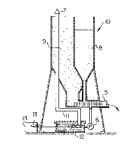
Figure 1 is a schematic diagram which illustrates the
present invention used in conjunction with a prior art mixer;
and
Figure 2 is a schematic diagram which illustrates the
components of the heating unit used with the present
invention.
Description of the Preferred Embodiments
Figure 1 illustrates the heating system of the present

4 2~2~g~
invention which includes a water tank 12 that is placed at the
bottom of a silo 10. Silo 10 is divided into two partitions,
an aggregate portion g and a binder portion 8 . A f ire tube 13
enters the side of water tank 12 and continues a substantial
5 distance into the tank 12. The fire tube 13 then turns
through 90 and emerges upwardly through the top of tank 12 as
pipe 11. The pipe 11 continues vertically up through
aggregate portion g of silo 10 and out the top of silo lo to
an exhaust port 7 to exhaust warm air to the atmosphere. A
heating unit 14 supplies the required heat energy to be
directed into fire tube 13.
A first heat exchanger is established inside water tank
12 between the portion of fire tube 13 that is submerged in
water ~ithin tank 12 and the water itself. Approximately 3
ft. of pipe contacts the water in tank 12. The heat exchange
causes the temperature of the water in tank 12 to increase to
about 110F. The warmed water is then pumped into a mixing
unit 5 by a water pump 6. The above mentioned water
temperature is sufficient for the proper mixing of mortar even
in very cold winter conditions.
A second heat exchanger is established between that
portion of pipe 11 exposed to the air between water tank 12
and silo 10. The heat that radiates from pipe 11 in this
region heats mixing unit 5 to prevent the materials from
~5 freezing during the mixing process.
A third heat exchanger is established between the portion
of pipe 11 contained in aggregate portion 9 of silo 10, and
the aggregate itself. The radiant heat from pipe 11 maintains

the temperature of the aggregate and inhibits freeæing.
The temperature of the heat energy that passes through
fire tube 13 varies from approxima~ely 800F, but changes with
ambient temperature, at the entrance to fire tube 13 to 250F
at exhaust port 7. If the temperature at exhaust port 7 is
lower than 250F the products of combustion may produce a
condensate on the interior walls of silo 10.
The heating unit 14, as shown in Figure 2, is used to
provide the required heat energy, in the form of the products
of combustion and secondary air, into fire tube 13 and pipe
11. The components which make up heating unit 14 are
connected to a supporting frame 16. The Insta Flame (TM)
brand of industrial propane heaters can be used as heating
unit 14.
1~ Propane gas is fed to heating unit 14 via a propane inlet
22. The gas is fed to the inlet of a shut off valve 24. Shut
off valve 24 feeds both a low flame by-pass tube 28 and a main
burner tube 25. The existence of a low flame in burner 18
heats a thermocouple 26 and maintains valve 24 in the open
position. If, for any reason, the low flame in burner 18 goes
out, thermocouple 26 would cool down and shut off all gas flow
through valve 24.
The main burner tube 25 is connected to a burner nozzle
29 via a control valve 20. A water temperature sensor 30
detects the temperature of water in tank 12. In this
particular embodiment, if the temperature of the water is
below some predetermined temperature, sensor 30 sends a
signal to control valve 20 to provide sufficient gas to nozzle

6 ~2~
29 to gradually increase the heat energy supplied to fire tube
13. Eventually, the burner 18 reaches the maximum heat energy
level that can be provided by heating unit 14. When the water
has reached the pre.determined value the flame is gradually
lowered to a low flame maintenance state.
This low heat is sufficient to provide enough heat energy
to maintain the water in tan~ 12 at the desired temperature,
in this case about llO~F.
If no water is in tank 12, an operator can manually set
burner 18 to a low flame state. This low heat is sufficient
to maintain aggregate 9 in silo 10 at a temperature above
freezing. In this configuration the mortar mixing unit is
maintained in a standby condition either at the mixing site or
when being transported.
In view of the above, twc embodiments of the invention
are provided. The first embodiment integrates water tank 12
and heating unit 14 with the mortar mixing apparatus so that
the aggregate can be heated at all times including during
transport of the mortar mixing apparatus. The other
embodiment separates the mortar mixing apparatus from the
heating unit 14 thereby allowing the heating unit 14 to be
utilized only when needed at the mortar mixing site.

Dessin représentatif
Une figure unique qui représente un dessin illustrant l'invention.
États administratifs

2024-08-01 : Dans le cadre de la transition vers les Brevets de nouvelle génération (BNG), la base de données sur les brevets canadiens (BDBC) contient désormais un Historique d'événement plus détaillé, qui reproduit le Journal des événements de notre nouvelle solution interne.

Veuillez noter que les événements débutant par « Inactive : » se réfèrent à des événements qui ne sont plus utilisés dans notre nouvelle solution interne.

Pour une meilleure compréhension de l'état de la demande ou brevet qui figure sur cette page, la rubrique Mise en garde , et les descriptions de Brevet , Historique d'événement , Taxes périodiques et Historique des paiements devraient être consultées.

Historique d'événement

Description Date
Inactive : CIB expirée 2022-01-01
Inactive : CIB de MCD 2006-03-11
Demande non rétablie avant l'échéance 2001-07-30
Inactive : Morte - Aucune rép. dem. par.30(2) Règles 2001-07-30
Réputée abandonnée - omission de répondre à un avis sur les taxes pour le maintien en état 2000-11-14
Inactive : Abandon. - Aucune rép dem par.30(2) Règles 2000-07-28
Inactive : Dem. de l'examinateur par.30(2) Règles 2000-01-28
Lettre envoyée 1997-11-28
Inactive : Renseign. sur l'état - Complets dès date d'ent. journ. 1997-11-28
Inactive : Dem. traitée sur TS dès date d'ent. journal 1997-11-28
Exigences pour une requête d'examen - jugée conforme 1997-11-13
Toutes les exigences pour l'examen - jugée conforme 1997-11-13
Demande publiée (accessible au public) 1992-05-14

Historique d'abandonnement

Date d'abandonnement Raison Date de rétablissement
2000-11-14

Taxes périodiques

Le dernier paiement a été reçu le 

Avis : Si le paiement en totalité n'a pas été reçu au plus tard à la date indiquée, une taxe supplémentaire peut être imposée, soit une des taxes suivantes :

  • taxe de rétablissement ;
  • taxe pour paiement en souffrance ; ou
  • taxe additionnelle pour le renversement d'une péremption réputée.

Veuillez vous référer à la page web des taxes sur les brevets de l'OPIC pour voir tous les montants actuels des taxes.

Historique des taxes

Type de taxes Anniversaire Échéance Date payée
TM (demande, 7e anniv.) - petite 07 1997-11-13 1997-11-12
Requête d'examen - petite 1997-11-13
TM (demande, 8e anniv.) - petite 08 1998-11-13 1998-11-12
TM (demande, 9e anniv.) - petite 09 1999-11-15 1999-11-15
TM (demande, 2e anniv.) - générale 02 1992-11-13
Titulaires au dossier

Les titulaires actuels et antérieures au dossier sont affichés en ordre alphabétique.

Titulaires actuels au dossier
FRAMIX CANADA INC.
Titulaires antérieures au dossier
ALLEN A. NEUFELDT
BRYAN KIESWETTER
Les propriétaires antérieurs qui ne figurent pas dans la liste des « Propriétaires au dossier » apparaîtront dans d'autres documents au dossier.
Documents

Pour visionner les fichiers sélectionnés, entrer le code reCAPTCHA :


Pour visualiser une image, cliquer sur un lien dans la colonne description du document. Pour télécharger l'image (les images), cliquer l'une ou plusieurs cases à cocher dans la première colonne et ensuite cliquer sur le bouton "Télécharger sélection en format PDF (archive Zip)" ou le bouton "Télécharger sélection (en un fichier PDF fusionné)".

Liste des documents de brevet publiés et non publiés sur la BDBC .

Si vous avez des difficultés à accéder au contenu, veuillez communiquer avec le Centre de services à la clientèle au 1-866-997-1936, ou envoyer un courriel au Centre de service à la clientèle de l'OPIC.


Description du
Document 
Date
(aaaa-mm-jj) 
Nombre de pages   Taille de l'image (Ko) 
Abrégé 1993-11-20 1 14
Dessins 1993-11-20 1 21
Revendications 1993-11-20 2 46
Description 1993-11-20 6 193
Page couverture 1993-11-20 1 12
Dessin représentatif 1999-03-01 1 10
Rappel - requête d'examen 1997-07-13 1 117
Accusé de réception de la requête d'examen 1997-11-28 1 178
Courtoisie - Lettre d'abandon (R30(2)) 2000-09-11 1 171
Courtoisie - Lettre d'abandon (taxe de maintien en état) 2000-12-12 1 183
Taxes 1998-11-12 1 44
Taxes 1996-11-13 1 52
Taxes 1993-10-08 1 59
Taxes 1994-11-04 1 45
Taxes 1995-11-14 1 57
Taxes 1992-11-12 1 19