Note : Les descriptions sont présentées dans la langue officielle dans laquelle elles ont été soumises.
u'~ i
RD-q330
T~TLE
Sensor-Holding Device
~ackground of the Invention
This invention relates to ~ ~ensor-
holding device and, more particularl~, to ~ æensor-
holding device which permits removal of sensors
used for on-line mea~urements of a fluid ~tream
flowing iD a pipe without interrupting fluid flow.
Exi~ting on-line fluid rheological,
physical property, and particulate-6ensing devices
are mounted flush with the pipe wall ~nd tend to
coat with fouling residue resulting in inaccurate
measurements or premature failure of the ~en~or.
Such an arrangement does not allow for on-line
cleaning, maintenance, adjustment, or replacement
of the censor elements. It instead require6
shutdown and flushing of the ~ystem in order to
remove the ~ensor components for replacement or
maintenance, which takes considerable time and
reduces production output.
Summary of the Invention
The pre~ent invention overcomeR these
problems by providing a sen~or-holding device which
allows for ea~y on-line maintenance or replacement
of sensors without fluid stream ~hutdown. The
device i~ useful for holding a wide variety of
censor types, including, but not limited to, light,
ultrasonic, temperature and pre~6ure ~ensors. In
one embodiment, the device provides 6tems which may
be advanced and retracted independently ro as to
allow for both the ~djustment of the di~tance
between 6ensor windowE or end~ and adju6tment of
the po~ition of the 6ensor~ in the fluid ~tream.
One or both ~tems ~ay be hollow to hold ~ one or
two component sensor, respectively. When the 6tems
are in their fully advanced po6itions, intimate and
~ leak-proof contact of the stem~ i~ provided between
the two mating stem surfaces. This permit~ the
~ensor element6 to be removed for maint~nance and
rein~talled with no interruption of the fluid
stream.
Brief De~cription of the Drawings
Fig. l is a cross-sectioned side
elevation view illustrating an embodiment of the
pre~ent invention in which both stem6 mty be
advanced and retracted without rotating, and may be
advanced and retracted independently of each other,
lS and in which sensor elements are contained in both
stems of the device.
Fig. 2 is a cross-~ectioned end elevation
view of Fig. l taken along line 2-2.
Fig. 3 i~ a plan view partially in
section of Fig. 1 illustrating the rotational
mechanism for rotating the 6tems.
Fig. 4 i~ a cross-6ectional side
elevation view of an embodiment of the device in
which one ~tem i8 6tationary and one 6tem is
retractable.
Detailed Description of the Illustrated Embodiments
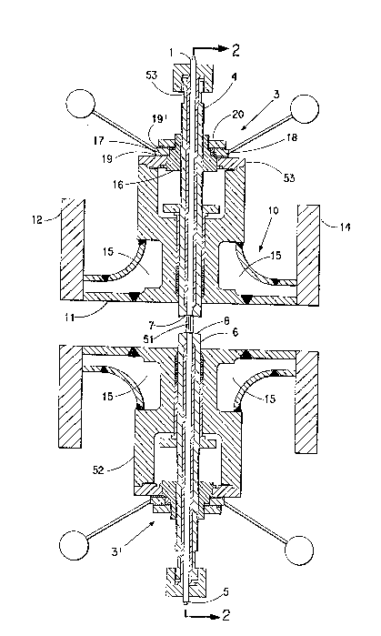
Referring to Figs. 1-3, the 6ensing
apparatu6 includes a body 10 defining a fluid flow
path 11 therethrough fro2 an inlet end flange 12 to
an outlet end flange 14 for connection to
~ubsequent piping. ~he body ~ay also be welded
directly into an exicting pipel$ne. Non-rotating
hollow ~tem~ 4 and 6 are advanced and retracted by
mean6 of stem operating mechan~em6 3 and 3'. In
the particular ~mbodiment 6hown, 3 and 3' are
u ~ ~
rising stem mechanisms assembled from nut 16 which
i6 keyed to handle 17 by key 18. Wa6her6 19 and
19' are in6erted between handle 17 and device body
flange 53 and nut 20. Nut 20 is threaded onto 16
to 6ecure the ri6ing stem mechanism together.
Rotation of handle 17 cause6 nut 16 to rotate which
re6ults in the upward or downward motion of stem 4
which i6 threaded into nut 16. Slot 27 machined
into 6tem ~ restrict6 the travel distance of the
~tem by means of key 28. The key is captured by
plate 29 secured by bolt6 50 and 50' to plate 26.
An identical arrangement i6 provided for stem 6.
U6e of a ri6ing 6tem mechani6m eliminates any
problems with entanglement of wires or other
connections to the sen60r probe6 that might occur
if the 6tem were required to rotate when advanced
and retracted. However, a rotating stem could be
effectively employed with a swivel coupling for the
~ensor lead wire or other means of instrument
signal transmission.
The 6ensor component6 con6ist of
observation and illuminatioin probe6 1 and 5 u6ed
for particle detection. An ex~mple of such a
sensor is described in U.S. Patent No. 4,529,306.
The probes 1 and 5 are contained in the hollow
6tems 4 and 6, respectively. They are held in
place and maintained in a leak-tight condition by
being either in a packing arrangement with or being
threaded or gasketed into the stem~ 4 and 6.
Probes 1 and 5 are further ~ecured in the stem6 by
mean6 of caps 16 and 16' and lock ~crews 17 and
17'.
A packing arrangement $s ufied to maintain
stems 4 and 6 in a leaktight condltion in device
body 52. More particularly, the packing
arrangement (Fig6. 1 and 2) i6 a66embled from
bushing 21, packing rings 22 ~eparated by metal
waters 23, and sleeve 24 which acts as a packing
follower. This packing arrangement may be
compressed to effect a leaktight 6eal by tightening
6crews 25 and 25' which are threaded through plate
26 which presses against 61eeve 24 and device body
52. This packing arrangement prevent6 fluid from
the pipeline from leaking between the 6tems and the
body of the device. The sensor6 1 and 5 are
recessed 61ightly into the hole6 in the 6tems 4 and
6 to prevent contact of the 6ensor face~ when the
device is in a closed po6ition. Sensor ends in
contact with the fluid may be provided with
jewelled windows, as in the case of ~ensors using
light, x-ray, or ~imilar elements. Sensors which
require direct contact with the fluid will not need
this protection.
The 6tems are advanced and retracted to
expose the light path 51 to the flowing fluid path
11. The depth of view is varied by adjustmPnt of
the separation distance between the 6tems 4 and 6.
The sampling zone may be varied by moving both
stems simultaneously by equal distances in the
desired direction. When the 6tems are fully
2~ advanced, intimate contact of the 6tem 4 concave
6ur,ace 7 and the stem 6 convex ~urface 8 i~olates
the ~ensor from the fluid flow path 11 and permits
the removal, cleaning and reinstallation of the
probes 1 and 5 while allowing fluid flow to
continue uninterrupted. The device may be provided
with a jacket means 15 for circulation of a heat
transfer fluid if required to maint~in the fluid in
a molten or heated ~tate, ~ in a polymer 6tream.
In the event that the 6tem surface6 7 and
8 become fouled, a me~ns i6 provided for cleaning
these surface6 without the need for process stream
v~
~hutdown. Slot 27 i6 machined 60 as to allow for
an approximately 90 degree rotation of 6tem 4. ~ey
28 prevents further rotation. By advancing the
stems until surfaces 7 and 8 are in contact,
gripping stem 4 at flat6 53 u~ing a wrench or other
means, and rotating both ~tem 4 and handle 17 back
and forth at the 6ame time, ~tem 4 i6 cau6ed to
rotate back and forth relative to etem 6 while
maintaining contact of the 6tem 6urface6 7 and 8,
thus wiping the surface~ to clean them. The
arrangement of ~tem 6 is identical to that of 6tem
4, allowing for rotation of either or both of 6tems
for cleaning purposes.
Fig. 4 illustrates another embodiment of
the present invention in which the ~tem 32 i~
movable but in which the ~eat 34 is fixed.
Operation i5 ~imilar to the-embodiment given in
Figs. 1-3. The stem 32 i6 advanced and retracted
by means of stem operating mechanism 33 which may
be identical to the rising 6tem mechanism
illustrated in the embodiment of Figs. 1-3. Stem
32 may also ~e designed to provide for rotation
relative to stem 34 for cleaning purpose~ as ~hown
in the embodiment of Fig~. 1-3. The depth of view
may be ~d~usted by varying the porition of the
non-rotating ~tem 32 in the fluid path 31. When
~tem 32 is in its fully advanced po~ition, intimate
contact of the Etem and seat 6urfaces 37 and 3
provides ~ le~k-proof seal, thus ~llowing the
removal, cleaning and rein~tallation of the sen~or
probes 35 and 36. The device may ~l o be provided
with a jacket means 39 for circulation of heat
tran6fer fluid ~f required.
The above descr~ption i~ provided by way
of example only. The ~en~or end, holding device
~tem and ~eat openings, ~nd windows may be
iJ '1
redesigned depending on the requirement6 of a
particular sen60r device to provide a leak-tight
fit. A variety of 6eat/6tem complementary mating
configurations, 6uch as tapered, rounded, flat,
convex/concave and concave/convex, are pos6ible.