Note : Les descriptions sont présentées dans la langue officielle dans laquelle elles ont été soumises.
203 1 6~3
CATV S~BSCRIBER DISCONNECT SWITCH
This application i8 related to the following patents:
Canadian No. 1,334,444, issued February 14, 1995; U.S. No.
5 5,014,309, issued May 7, 1991; U.S. No. 5,142,574 issued
August 25, 1992; U.S. No. 5,208,854, issued May 4, 1993;
and U.S. No. 5,109,286, issued April 28, 1992.
TECHNICAL FIELD
This invention relates generally to the field of cable
20 television systems and, more particularly, to a method and
apparatus for selectively denying service in such systems.
BACRGROUND ART
At a headend of a cable television system, a scrambler
is normally provided to encode premium television channels.
The applied scrambling precludes reception by an unauthorized
converter/decoder at a connected premises. Data representing
channels or tiers of programming are addressably transmitted
30 to a particular converter/decoder and stored in an
authorization memory. As a result of the addressed
transmission, a subsequently transmitted program is authorized
in that the decoder portion of the converter/decoder will be
selectively enabled to decode the scrambled premium channel
35 or program.
Several varieties of scrambling techniques are applied
today. Each manufacturer has its own scheme which may be
203:L6~3
incompatible with others. Nevertheless, most popular
scrambling systems today are based on sync suppression, in
which the sync information is hidden from the television
receiver's sync separator, usually by moving it to a level
5 occupied by picture information (moving the sync tip to an
equivalent picture level of 40 IRE units is common). Some
systems modulate the picture carrier with a sine wave phased
to suppress the horizontal blanking interval. Most systems
today switch to the suppressed level at the beginning of the
10 blanking interval and switch out at the end. Most though not
all suppress the vertical blanking interval. Some systems
dynamically invert the video, either on a lineby-line or a
field-by-field basis. This must be done carefully to avoid
artifacts caused by inverting and reinverting around different
15 levels, and by differential gain and phase of the system.
Synchronization is restored either by the provision of
synchronous amplitude modulated pulses on the sound carrier,
digital information placed in the vertical interval or phase
modulation on the picture carrier.
The provision of one scrambler per premium channel at the
headend and the inclusion of a descrambler in each
converter/decoder at the premises of the television receiver
is particularly expensive. Furthermore, providing the
converter/decoder on premises has turned out to be a great
25 temptation to service pirates who imaginatively seek ways to
receive premium channels. As a result, cable television
equipment manufacturers have entered into a veritable war with
such pirates resulting in complicated service authorization
protocols in some instances involving multiple layers of
30 encryption by both in-band and out-of-band data transmission
further increasing the costs of the converter/decoder.
The cable industry has begun to look for new technology
and to take a second look at technology developed in the early
stages of development of cable television, such as the
35 application of negative and positive traps and more recent
techniques such as interdiction.
Negative trap te~hnology is viewed by many
29~1603
manufacturers as a viable alternative to sync suppression
scrambling methods. A negative trap is basically a narrow
band reject filter. Traps are located at the drop to a
subscriber's dwelling and attenuate a significant portion of
5 a premium television channel rendering that channel unusable
by the subscriber.
In the conventional embodiment, negative traps are
made using L-C filter techniques. The result is a notch with
finite quality Q and finite shape factor. In the case of a
10 single channel negative trap, the center of the notch is
usually located at the picture carrier frequency of the
channel to be removed. This technique, sometimes called a
static negative trap, requires attenuation at the picture
carrier of at least 60 dB to be effective.
Negative trap systems have several advantages that
make them attractive for cable television applications. One
primary advantage is the ability to deliver a broadband cable
television spectrum to the subscriber's converter/decoder.
Conventional sync suppression systems utilize descrambling
20 set-top converter/decoderswhich deliver inherently narrowband
signals. Negative traps are usually mounted outside the
subscriber's home (typically at the tap) and thereby minimize
the exposure associated with placing hardware inside the
subscriber's dwelling. Finally, some cable television
25 operators view the negative trap as a more secure means of
subscriber control than is sync suppression, as picture
reconstruction is viewed as substantially more difficult.
However, the negative trap system requires hardware in
locations where no revenue is generated for the cable
30 television system. Moreover, negative traps have several
severe practical limitations. L-C band re;ect filters have
Q and shape factor limitations. Quality factors Q for L-C
filters may be limited to around 30. This means that for a
negative trap located at chAnnel 8 (picture carrier at 181.25
35 MHz) the 3 dB bandwidth of a negative trap is typically 6 MHz
(or the bandwidth of a hAsehAnd television channel). This
trap would result in significant deterioration of the lower
L 6 C1 3
adjacent channel. Then the television receiver tuned to the
lower adjacent channel, rather than having to contend with a
15 dB picture-to-sound ratio, may have to contend with a sound
carrier reduced an additional 6 dB or so. Frequency stability
5 as a function of time and temperature is also a significant
concern. Many cable television system operators have
instituted a regular negative trap change-out program based
on the assumption that after a certain period of time and
temperature cycling, freguency drift will render negative
10 traps useless.
Positive trap systems also utilize a narrow band--
rejection notch filter. However, unlike negative trap systems
which are used to attenuate or trap a premium channel
transmission, the notch filter is used to restore the premium
15 television channel. In this scenario, an interfering signal
is placed inside the premium television channel at the cable
television headend. This interfering signal is then removed
at the subscriber's dwelling by use of the notch filter.
Ideally this notch filter removes only the interference
20 without removing a significant amount of television
information.
Parallel to developments of different types of
trapping or jamming systems, the cable industry has also
evidenced a requirement to move a converter or descrambler
25 outside of a subscriber's home to a location which is more
secure from signal piracy. This concept is not new; for
example, an addressable tap system was developed by Scientific
Atlanta in 1983 or 1984 in which an off-premises "tap",
addressed by a headband control system, gates a premium
30 channel into the subscriber's premises. However, such
products did not prove to be viable alternatives to inside-
the-home signal descrambler/converters.
Another scrambling system proposed by Scientific
Atlanta involved a t~c~nique of intentionally dropping a field
35 of video signal on occasion such that an unauthorized
recipient would not be able to view a properly synchronized
image. Depending on how fast the subscriber's television
2~33~&3
receiver may restore synch, the image would appear to flash
on and off.
A relatively recent technique for premium channel
control is the interdiction system, so-called because of the
5 introduction of an interfering signal at the subscriber's
location. Most embodiments consist of a pole-mounted
enclosure located outside the subscriber's premises designed
to serve four or more subscribers. This enclosure contains
at least one microprocessor controlled oscillator and switch
10 control electronics to secure several television channels.
Control is accomplished by injecting an interfering or jamming
signal into unauthorized channels from this pole-mounted
enclosure.
For efficiency's sake, it is known to utilize one
15 oscillator to jam several premium television channels. This
techn;que not only reduces the amount of hardware required,
but also maximizes the system flexibility. The oscillator
output jamming signal frequency is periodically moved from
channel to channel. Consequently, the oscillator is frequency
20 agile and hops from jamming one premium channel frequency to
the next.
One such system is known from U.S. 4,450,481 in which
a single frequency agile oscillator provides a hopping gain-
controlled jamming signal output to four high frequency
25 electronic switches. In this known system, each switch is
associated with one subscriber drop. Under microprocessor
control and depending on which subscribers are authorized to
receive transmitted premium programming, the microprocessor
selectively gates the jamming signal ouL~u~ of the single
30 oscillator via the switches into the path of the incoming
broadband television signal to each subscriber. Consequently,
an unauthorized subscriber upon tuning to a premium channel
will receive the premium channel on which a jamming signal at
approximately the same frequency has been superimposed.
3S In the known system, it is indicated that sixteen
channels may be jammed by a single voltage controlled
frequency agile oscillator. With respect to one premium
6 203 1 603
channel, this translates to a situation in which the jamming
signal can only be present one sixteenth of the time or an
approximately 6% jamming interval. The rate of hopping is
also indicated at 100 bursts per second of jamming signal at
5 a particular frequency, or a 100 hertz hopping rate.
Consequently, the effectiveness of the jamming signal is
questionable.
It is important that an interdiction system jamming
signal frequency be placed as close as possible to the picture
10 carrier frequency. Otherwise, adjacent channel artifacts or
incomplete jamming will result. In the known system, the
jamming signal is intentionally placed below the video carrier
and consequently approximate to an adjacent channel producing
adjacent channel artifacts.
To overcome the difficulties of such prior art
interdiction systems and in accordance with Canadian Patent
No. 1,334,444 and U.S. Patent No. 5,014,309 and the other
U.S. patents referenced previously, and improved interdiction
system is described. For example, cost reduction is achieved
20 for each subscriber unit or common circuitry associated with
several subscriber units as, for example, is provided by
Figure 2 of Canadian Patent No. 1,334,444.
In most if not all of these systems for scrambling or
25 jamming CATV channels, situations arise when it is appropriate
to deny service to a particular subscriber or even deny
service generally to all subscribers. The more obvious
occasions for a service disconnect are the subscriber's
failure to pay for service or in response to the request of
30 a subscriber who no longer desires service. Other occasions
may relate to emergency conditions such as those caused by
weather, national defense or act of God.
Typically, a disconnect command is transmitted to a
subscriber decoder, converter, jammer or interdiction device
35 over a special carrier or is imbedded in the vertical blanking
interval of a transmitted video carrier. Upon receipt, the
subscriber unit decodes the command, determines the command
7 203 1 603
is to be performed by the particular unit and executes the
command. The command is executed, for example, by turning off
power to signal conversion apparatus, by operating a
subscriber disconnect relay or switch or by turning off power
5 to amplifier circuits or by other techniques known in the art.
Generally it is a principle of design of any such
subscriber disconnect arrangements that as much as sixty or
seventy dB of isolation be provided by the isolating device.
For example, when power is turned off to signal conversion
10 apparatus, there should only be a highly limited amplitude of
signal passed to the subscriber. This is equally true for
disconnect relays, powered down amplifiers, or any other known
disconnect techniques. Providing such a great amount of
isolation may be expensive as it may require additional
15 equipment, circuits, or special control to accomplish.
Thus there exists a problem with present disconnect
arrangements in their difficulty of achieving adequate
isolation with an economical device. When service is
disconnected, it is desirable to reduce the signal level
20 reaching the subscriber's television receiver so that, under
worst case conditions, the subscriber's television receiver
will not receive a viewable image, no matter how sophisticated
the receiver. These worst case conditions include
simultaneously encountering a television receiver having
25 excellent noise rejection performance, a low noise
preamplifier installed in the subscriber's home wiring, the
subscriber's being connected to a short drop cable having low
attenuation, and a CATV distribution network providing a
relatively high power level radio frequency input signal to
30 the subscriber's premises. Under these conditions, it is
difficult to provide an economical switch with adequate
isolation which can guarantee that an unviewable image will
be received.
DISCLOSURE OF THE lNv~NllON
It is an object of an aspect of the present invention to
provide an efficient, cost-effective apparatus and method of
denying
203 1 603
service to subscribers of a cable television system.
It iæ an object of an aspect of the present invention
to provide an improved service denial device while reducing
the degree of isolation provided by the device.
It is an object of an aspect of the present invention
to provide an improved service denial device which permits
the subscriber to view predetermined timed portions of a
scrambled or encoded broadcast.
It is an object of an aspect of the present invention to
10 provide an improved service denial device which functions at
the same time to permit a personal subscriber message to be
displayed indicating why service is being denied.
In accordance with achieving the objects of the
present invention, it is a principle thereof to provide a
15 service denial device of limited isolation. In particular,
the isolation provided by any such device may be only thirty
or forty dB instead of sixty or seventy dB. In fact, only 20
dB of isolation may be necessary in some situations. In
accordance with the principles of the present invention, the
20 device is repeatedly activated and deactivated instead of
being permanently activated during the period of service
denial.
In one embodiment implemented in an off-premises
interdiction device as first suggested in our patent appli-
25 cation Canadian Patent No. 1,334,444, a service denial switchis connected in series with a radio frequency signal
amplifier. Power to the amplifier and control of the switch
are determined by a microprocessor of a subscriber unit of the
system. In accordance with the principles of the present
30 invention, the switch only need be an inexpensive PIN or
simple diode. The microprocessor during the period of service
denial either outputs or controls the generation of a control
signal wave having a longer activation period than a
deactivation period at a toggling frequency, for example,
35 between 30 hertz and 15 kilohertz. In other words, the
maximum length of time a service denial device should be
maintained in either an activated or a nonactivated state
2~3~6~33
should be equivalent to about one television field, or about
16.7 milliseconds. The minimum time the device should be in
one or the other condition should be on the order of the
duration of one synch pulse, for example, 4.7 microseconds.
The object of the on/off toggling or switching of
service denial is to preclude even a sophisticated television
receiver from achieving synchronization to the incoming video
signal. The selected toggling frequency should avoid 15,734
hertz, the horizontal line rate, its harmonics or its
10 subharmonics. Otherwise, a sophisticated television receiver
may be able to obtain synch.
When any subscriber unit is removed from service, the
subscriber unit responds in the same manner to a service
disconnect command as in any known technique in that a command
15 is received, verified and decoded. However, in accordance
with the present invention, the service denial device is not
maintained in a permanently on condition during the period of
service denial. Rather, the device is activated and
deactivated at a predetermined rate which precludes a normal
20 television receiver from achieving synchronization. As a
result, an undiscernible image will appear on a television
screen.
In accordance with another embodiment of the present
invention, the respective timing intervals when a control
25 signal is provided for activating and deactivating the program
denial device are randomly varied. The length of time the
device is activated or deactivated (for example, a service
denial switch is open or closed) may be randomly varied within
the limits specified above to thwart a service pirate from
30 obtaining unauthorized service and provide additional radio
frequency signal security. A program of the microprocessor
for controlling the service disconnect switch of the
subscriber unit of the above-described off-premises
interdiction system may determine the random control signal
35 waveform it ouL~uLs to the ~LGyLam denial device.
At the same time the program ~Pni~l switch is
activated and deactivated in this embodiment, the
203~1~03
microprocessor may simultaneously provide the same control
signal as a power down signal to the radio frequency signal
amplifier. In this manner, both the diode switch and the
amplifier form a program denial device. Furthermore, the
5 switch could be eliminated from the device and the powering
down of the amplifier alone may serve as the service denial
device.
In accordance with a still further embodiment of the
present invention, an amplitude modulator or simple multiplier
10 circuit may replace the service disconnect switch. The
amplitude modulator or multiplier multiplies the incoming
radio frequency signal with a multiplier control signal which
varies from no signal level to a level representing one. The
microprocessor of the subscriber unit may output the same
15 waveform of the previously described embodiment as the
multiplier control signal waveform of this embodiment or may
output practically any waveform for obfuscation involving
varying depths of modulation.
In either embodiment involving a switch or involving
20 a signal multiplier, the signal for controlling the amplitude
modulator or multiplier may be provided for a relatively long
period, for example, for thirty seconds and removed for a
relatively short period, for example, for ten seconds. In
this manner, a television signal will appear for a brief
25 period of time and become distorted for a longer period of
time operating as a teaser to a subscriber, encouraging the
subscriber to subscribe to otherwise unauthorized services.
Furthermore, the thirty second/ten second intervals may be
varied in a random manner by a program of a controlling
30 processor.
This concept of teasing a would-be subscriber has
broader application than serving as a service denial device
and may be more generally implemented, for example, as a way
of controlling a scrambling process for scrambling premium
35 channel program transmissions. This teasing techn;que differs
from a preview period known in the art in that the timed
control of scrambling is implemented during the entire period
2031~3
of the premium program as a teaser and not just for a
predetermined preview period.
Furthermore, in accordance with the present invention,
and as an embellishment of the program denial device involving
5 an amplitude modulator or multiplier, a separate private
message channel may be implemented without considerable
circuit modification. Between the microprocessor and the
modulator is provided a character generator which outputs a
synchronized video waveform with an embedded character data
10 message, for example, stating why the service to the customer
has been denied. This control signal then is multiplied times
the incoming broadband waveform and effectively scrambles the
waveform. At the same time, the message will be modulated on
a continuous wave carrier channel reserved for personal
15 messages. In this instance, the control waveform provides
synch and causes a personal message to appear on an otherwise
blank background.
To reduce costs associated with providing a character
generator which provides a synchronized waveform output with
20 embedded character messages, a more simplified character
generator having no synch generation capability may be applied
in this embodiment with some modification. A signal on a
particular carrier channel transmitted toward a subscriber
includes data embedded in the vertical blanking interval. It
25 is passed by a channel filter and recovered at a demodulator.
The demodulated channel is provided to a synch stripper and
to a vertical blanking interval data recovery circuit. The
recovered data drives a microprocessor to provide a message
ou~u~ to a character generator having no synch generation
30 capability coupled to the synch stripper. The synch stripper
strips synch from the partic~lar demodulated channel for
synchronizing the character generator. This character
generator then does not provide a synchronized waveform output
and so may be less eY~ncive to provide. Yet a synchronized
35 ouL~uL waveform for controlling the multiplier is ou~uL from
the character generator. Furthermore, the microprocessor may
either provide a modulation control signal or control a
203 1 6~3
12
service denial switch as described above in
connection with the first described embodiment of the
present invention.
Other aspects of this invention are as follows:
Service denial control apparatus for use in a
television service delivery system for automatically denying
service to a service subscriber, the service denial control
apparatus comprising
control means for controlling the generation of a
control signal waveform, and
service denial means, responsive to the control
signal waveform, for switchably regulating the delivery of
service including a television signal,
the control signal waveform being continuously
provided during a service disconnect period, the service
disconnect period comprising on and off periods, each having
predetermined durations within the range of durations between
the duration of a synchronizing pulse and the duration of a
field interval, the predetermined durations being further
predetermined to avoid durations related to synchronization
of the television signal.
Service denial control apparatus for use in a
television service delivery system for automatically denying
television service to a subscriber, the service denial control
apparatus comprising:
a controller for controlling the provision of a
control signal waveform during a period of service denial, and
a service denial device having low isolation and,
responsive to the control signal waveform, being toggled
between first and second states at a rate precluding a
television receiver coupled to the output of the device from
achieving synchronization.
~P
12a 2 0 3 1 6 ~ 3
Service denial control apparatus for use in a
television service delivery system for automatically denying
television service to a subscriber upon command, the service
denial control apparatus comprising:
a data receiver for receiving data transmitted from a
headend,
a data decoder, responsive to the data receiver for
decoding the received data,
a data processor, responsive to the data decoder, for
processing the data and for controlling the generation of a
control signal waveform when the processed data comprises a
disconnect command requiring a disconnection of service to the
subscriber, and
a service denial device, responsive to the control
signal waveform, being toggled between first and second states
at a rate precluding a television receiver coupled to the
output of the device from achieving synchronization.
Television service delivery apparatus for
encouraging subscription to premium television service
comprising
control means for controlling a generation of a
control signal waveform, and
a service delivery device responsive to the
periodic control waveform for delivering a premium television
service during a period of service denial, the period of
service denial comprising a succession of brief intervals of
service delivery and long intervals of service denial.
A method of denying television service to a
subscriber comprising the steps of:
during a period of service delivery, delivering
television service to the subscriber,
at the time of a period of service denial,
transmitting a subscriber service disconnect message uniquely
addressed to a subscriber unit, and
12b
203 1 603
5responsive to receiving the uniquely addressed
message, obfuscating the television service signal provided
to the addressed subscriber during a period of service denial
in a manner so as to preclude a subscriber's television signal
receiver from synchronizing to any received television signal,
10the signal obfuscation step further comprising the
step of toggling a service denial device between first and
second conditions.
15The advantages and features of the present method and
apparatus for providing an improved service denial and control
device for a jamming or interdiction or other CATV scrambling
system will now be explained in the following detailed
description of the invention with reference to the drawings.
BRIEF DESCRIPTION OF THE DRA~INGS
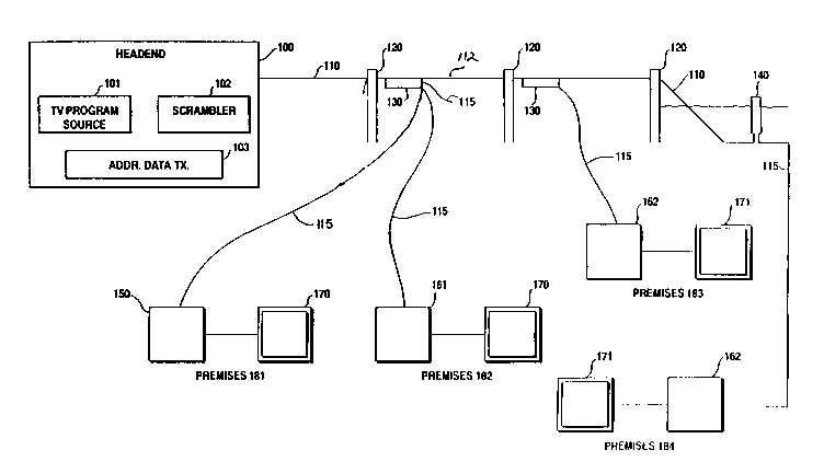
Figure 1 is an overall system block diagram showing
the service denial device and technique of the present
25invention implemented in an interdiction cable television
system.
Figure 2 is a block schematic diagram of an
addressable common control circuit for a plurality of provided
subscriber modules comprising a broadband signal tap, a
30microprocessor, a data receiver and decoder and an automatic
gain control circuit.
Figure 3 is a block schematic diagram of one
subscriber module comprising a microprocessor for selectively
actuating and deactuating a program denial device at a
35periodic rate according to the present invention comprising
a service denial switch and a radio frequency amplifier.
12c
203 1 603
Figure 4 is an exemplary control signal waveform
output of the microprocessor of Fig. 3 for actuating and
deactuating the program denial device shown in Figure 3 during
a period of service denial.
Figure 5 is a schematic circuit diagram of the radio
frequency amplifier of Fig. 3 and a control arrangement
therefor which meets the objectives of the present invention.
Figure 6 is a schematic block diagram of a program
denial device according to the present invention in which the
service denial switch is replaced by an amplitude modulator
or multiplier.
Figure 7 is a suggested waveform output of the
microprocessor whereby service is provided for a brief period
,~
13 2031 633
of time and denied for a longer period of time to tease a
subscriber into purchasing service.
- Figure 8 is a schematic block diagram of one
arrangement for providing a control signal to the amplitude
5 modulator shown in Figure 6 so that a personal message may be
delivered to the subscriber explaining why service has been
denied.
Figure 9 is a schematic block diagram of an
alternative arrangement for providing a personal message and
10 for controlling either a service denial switch according to
Figure 3 or an amplitude modulator according to Figure 6.
MODE(S) FOR CARRYING OUT THE lNv~..ION
Now the service denial device and method of the
present invention will be discussed in the context of the off-
premises cable television channel interdiction apparatus
first disclosed in Canadian Patent No. 1,334,444. On the
other hand, the present invention is in principle not limited
20 to service denial control circuitry for an interdiction
system but is also applicable to service denial control
circuits provided in positive and negative trap systems,
synch suppression systems and in any other system in which
service is denied responsive to a command from a headend
25 at an off-premises location proximate to or on a subscriber
premises.
A detailed discussion of the interdiction system in which
the present invention may be implemented is provided in
Canadian Patent No. 1,334,444 and U.S. Patent No. 5,014,309
30 and the other United States patents referred to hereinbefore.
Topics related to interdiction systems such as j~mm;ng
frequency and gain control will not be addressed in great
detail herein.
Referring more particularly to Fig. 1, there is shown a
35 generally block diagram of a cable television system employing
the principles of the present invention. By cable television
'''~B
2 ~ 0 ~
14
system is intended all systems involving the transmission of
television signals over a transmission medium (fiber optic
cable or coaxial cable) toward remote locations. For example,
a cable television system may comprise a community antenna
5 television distribution system, a satellite signal
distribution system, a broadcast television system, a private
cable distribution network, either industrial or educational,
or other forms of such systems. Each remote location of a
television receiver may comprise the location of a particular
10 subscriber to a subscription television service, plural
subscribers, single subscribers having plural television
receivers or private locations in a private cable distribution
network. Consequently, the term subscriber, when used in this
application and the claims, refers to either a private
15 subscriber or a commercial user of the cable television
system. Headend 100 as used in the present application and
claims is defined as the connecting point to a serving cable
or trunk 110 for distributing television channels over feeder
line 112 to drop 115 and finally to subscriber locations. For
20 reference purposes, an Electronic Industries Association
(E.I.A.) standard cable television frequency allocation scheme
is employed and referred to herein; however, by means of the
following disclosure of the present invention, one may apply
the principles to other known s~n~rds or non-st~n~rd
25 frequency allocations. Furthermore, a National Television
Subcommittee (N.T.S.C.) st~n~rd composite television signal
amplitude modulated onto a radio frequency carrier is
generally considered in the following description; however,
the principles of the present invention apply equally to other
30 st~n~Ard and non-st~n~rd television signal formats, including
proposed high definition television formats.
Headend 100 comprises a source of television
programming 101. Television ~toy~am source 101 may be a
satellite television receiver ~u~uL, a program produced by
35 a television studio, program material received over a
microwave or broadcast television link, a cable television
link GuL~uL, or any other source of television programming
2~3~6~
.
consistent with the present invention. The program source
material need not be limited to conventional television but
may comprise teletext, videotext, program audio, utility data,
or other forms of communication to be delivered to a remote
5 location over the serving cable or trunk line 110 and
subsequently over feeder line 112 and drop line 115.
Conventionally, trunk line 110, feeder line 112, and
drop line 115 are constructed of coaxial cable. For higher
performance, any one of these lines could be a fiber optic
10 cable. Preferably, due to the cost of the installation and
the need for a high quality initial transmission from headend
100, trunk line 110 is typically the only line constructed of
fiber optic cable.
Program material provided by source 101 may be premium
15 or otherwise restricted or desirably secured from receipt at
unauthorized receiver locations. To this end, each channel
or program to be secured is generally scrambled by scrambler
102 provided at headend 100. By the use of the term premium
channel or premium programming in the present application and
20 claims is intended a channel or program which is desired to
be secured from unauthorized reception either because of its
premium or restricted status.
Normally, all premium programming in known cable
television systems is scrambled or protected by negative
25 traps. However, in accordance with interdiction system
technology, premium programming is transmitted in the clear,
and interdiction is applied at off-premises interdiction
apparatus 130 to jam reception of unauthorized premium
programming.
Consequently, during a transition period in which
headend 100 provides scrambled television programming as well
as premium programing in the clear, a scrambler 102 will be
provided so long as converter/decoders 150 are provided to
subscribers for unscrambling scrambled program transmission.
35 In certain instances, converter/decoders 150 may be entirely
replaced by interdiction apparatus 1`30.
Also, at the headend, there is normally an addressable
2~31603
16
data transmitter 103 for transmitting global commands and data
to all subscribers or addressed communications for reception
by a unique subscriber. Such data transmission may be
conducted over a separate data carrier from the cable
5 television spectrum, for example, at 108.2 megahertz. It may
also be transmitted over an unused default carrier channel
from the television spectrum. Global commands generally take
the form of operation code and data while addressed
communications such as a subscriber disconnect command further
lO comprise the unique address of a particular subscriber.
In another alternative embodiment, such communications
may take the form of in band signals sent with a television
channel superimposed upon an audio carrier during, for
example, the vertical blanking interval of the video signal.
15 Such data communications further complicate data reception at
intervention apparatus 130 and are desirably eliminated.
However, in band signaling is sometimes required for the
operation of certain converter/decoders 150 known in the art.
Commands then to deny service to a particular
20 subscriber may be transmitted in-band or on a separate data
carrier and typically involve transmitting a unique address
of a particular subscriber unit, a command, and data. Data
transmission may be optional, and, if provided, may signal the
converter to display a particular message to the subscriber
25 as to why service is being denied. The decoders 150 receive
the command, decode it, determine if the command is to be
acted on, and if so perform the desired action such as operate
a service denial device and display a message.
Consequently, headend 100, cable television serving
30 cable or trunk line llO, and converter/decoders 150 and
television receivers 170 at a typical subscriber premises 181
comprise a typical cable television system. Channel program
or authorization data is transmitted via an addressable data
transmitter 103 over a trunk line 110 on feeder line 112. At
35 a pole 120 or from a pedestal 140 at underground cable
locations, the serving CATV signal is dropped via drop 115 to
a subscriber location. Drop 115 is connected to a
2 ~ 0 3
17
conventional converter/decoder 150 which serves several
functions. Responsive to an addressed communication from
headend transmitter 103, channel or program authorization data
is updated in an authorization memory if the address
5 associated with the addressed communication matches a unique
address of the subscriber decoder 150. For example, the sub-
scriber address may comprise a plurality of bits over and
above the actual number of subscribers in a system.
Additional bits, if provided, may insure the security of the
10 address. The premium channel or program is then stored in the
authorization memory of the converter/decoder 150. Television
programming is normally converted to an otherwise unused
channel such as channel 3 or 4 of the television spectrum by
a converter portion of converter/decoder 150. Its premium
15 status is checked against the data stored in authorization
memory. If the programming is authorized, the decoder portion
of the converter/decoder is enabled to decode authorized
scrambled premium programming.
The provided television receiver may be a conventional
20 television receiver 170 or may be a so-called cable ready
television receiver 171. Because of the advent of cable ready
television receivers 171, there is no longer a requirement at
a subscriber premises 181 for the converter portion of the
converter/decoder 150 as a converter is built into such
25 television receivers.
In accordance with a cable television system provided
with off-premises interdiction apparatus 130 of Figure 1, a
housing is mounted on a strand supporting cable 112, to a pole
120, or provided via a pedestal 140 or mounted outside the
30 premises on one exterior wall. Inside the housing is common
control circuitry for tapping into the broadband television
and data transmission spectrum. Referring to the first pole
120 from the left of Fig. 1, there is shown a strand-mounted
apparatus serving at least one drop or, per Fig. 1, two drops
35 115 to subscribers. Altogether, four or more subscribers and
up to four or more drops 115 may be served by interdiction
apparatus 130. Besides the common control circuitry, up to
2~3~6~3
four (or more) plug-in subscriber modules may be provided for
one housing. Also, if desired, additional services may be
provided via other plug-in units of the housing such as
impulse pay-per-view, subscriber polling involving two-way
5 data communication, meter reading, energy management or other
services.
Desirably, all equipment 161 may be removed from the
subscriber premises 182. However, for the provision of
additional services, some on-premises equipment may be
10 unavoidable. For purposes of this description, premises 182
will be assumed to include at least one non-cable ready
conventional television receiver 170. Consequently,
subscriber equipment 161 must at least comprise a tunable
converter for converting a received cable television channel
15 to an unused channel such as channel 3 or 4 for reception on
conventional television receiver 170.
Power for interdiction apparatus 130 may be provided
over the cable from the headend 100 or be provided via the
subscriber drop 115 or by a combination of such means.
20 Foreseeably, power may be even provided by rechargeable means
such as solar cells or other external or replaceable internal
sources such as batteries. Consequently, subscriber equipment
161 may also comprise a source of power for interdiction
apparatus 130.
Interdiction apparatus 130 may be secured in a tamper-
resistant housing or otherwise secured such as in a locked
equipment closet of an apartment complex. If located in a
place exposed to the elements, the housing should be water--
tight. Also, the housing should be designed to preclude radio
30 frequency leakage.
At premises 183, the subscriber is presumed to have a
cable ready television receiver 171. Consequently, subscriber
unit 162 may be entirely eliminated or comprise simply a power
feed to interdiction apparatus 130.
Premises 184 pictorially represents a subscriber
location served by an unde~y~ou,.d cable 110 via a serving
pedestal 140. Other pedestals (not shown) are for housing
203~603
19
cable distribution amplification and branching equipment in
buried cable installations. Pedestal 140 may comprise an off-
premises housing for interdiction apparatus 130. Subscriber
equipment 162 may comprise a converter, an additional service
5 device and a power unit as described in reference to
subscriber equipment 161 or nothing at all as described in
reference to subscriber equipment 162.
Interdiction apparatus 130 is uniquely addressable by
headend 100 just as is converter/decoder 150. If two bits of
10 a plural bit unique subscriber address are associated with
uniquely identifying one plug-in slot for one of four
subscriber modules, common control circuitry may be uniquely
addressed with remaining address data not used to secure the
data communication. Just as premium programming is
15 transmitted in the clear and since no data communication is
necessarily required with a subscriber premises, a subscriber
address need not be transmitted in a secure form.
Nevertheless, address security may be desirable so long as
converter/decoders 150 or other unique address requisite
20 equipment is provided at a premises.
Interdiction apparatus 130 comprises addressable
common control circuitry and up to four or more plug-in
subscriber modules. Upon receipt of subscriber specific
premium program or channel authorization data, the data are
25 stored at interdiction apparatus 130. Interdiction apparatus
130 further may comprise automatic gain control circuitry of
the common control circuitry. ~hAnn~l interdiction circuitry
associated with each subscriber module jams unauthorized
premium programming d~u~e~ via a particular drop 115 to a
30 particular subscriber. Co~equently, interdiction apparatus
130 is reasonably compatible with addressable authorization
data transmission known in the art. No scrambling of premium
channels (and no resulting artifacts) is necessary or
desirable. Furthermore, no additional forms of service
35 security are nececsAry such as channel encryption, in-band
channel or tier verification or other security measures. The
would-be service pirate must attempt to remove a particular
~16~3
- 20
pseudo-randomly timed jamming signal placed at a varying
frequency or seek to tamper with the off-premises apparatus
130 or derive a signal from shielded and bonded cable 110
which should likewise be maintained secure from radio
5 frequency leakage.
The common control circuitry of interdiction apparatus
130 will now be described by means of the block diagram Fig. 2
for serving four subscriber modules in accordance with the
block diagram Fig. 3. Referring particularly to Fig. 2, a
10 feeder cable 112 is shown entering interdiction apparatus 130
at FEEDER IN and leaving at FEEDER OUT. Power PWR may be
provided via the feeder cable or by means of subscriber drop
115 or locally by internal or external means. Depending on
the source of power PWR, input power may be of alternating or
15 direct current.
A directional coupler 210 which may be in the form of
a plug-in module taps into the broadband serving cable 110.
A broadband of radio frequency signals is thus output to
highpass filter 220 which, in this embodiment, is optional.
20 Highpass filter 220 passes a band of frequencies comprising
at least the data carrier frequency or frequencies (in a bi-
directional application) and the cable television channel
spectrum. The cable television spectrum may comprise a
frequency band from about 54 MHz to 550 MHz.
A common automatic gain control circuit as disclosed
in Fig. 2 comprises variable attenuator 230, RF amplifier 233,
directional coupler 232, and AGC control circuit 231. This
automatic gain control circuit appropriately regulates the
broadband RF signal power to fall within established limits.
30 The common circuitry of Fig. 2 is colocated or closely located
to the subscriber units which will be further described in
connection with Figure 3 and may be cont~ine~ in the same
housing.
Also connected to directional coupler 232 is a data
35 receiver 240 for receiving data from the addressable data
transmitter 103 located at heA~en~ 100. Data receiver 240
receives data transmitted, for example, over a data carrier
2~316~3
21
of 108.2 megahertz and provides unprocessed data to data
decoder 250. In accordance with an established protocol and
as briefly described above, such data may be in the form of
an operation code (command), a subscriber unique address and
5 associated data. Data decoder 250 processes the data and
provides the separately transmitted data to microprocessor 260
for further interpretation in accordance with a resident
algorithm. Microprocessor 260 is most efficiently chosen to
alleviate as many responsibilities from any microprocessor
10 provided for an individual subscriber module and so is most
conveniently an eight bit microprocessor having eight
kilobytes of internal code such as a Motorola 68HC05C8.
Received data may be stored in uninterruptable memory
270 by microprocessor 260. Data may be temporarily stored in
15 memory 270 or more permanently stored and subsequently
downloaded when needed to a subscriber module via a serial
peripheral interface bus connecting microprocessor 260 with
separate microprocessors 300 associated with each provided
subscriber module as shown in Fig. 3.
Variable gain unit 230 regulates the received
broadband of picture carriers while the microprocessor 260
controls the jamming carrier level outputs of associated
subscriber units within the prescribed range. Microprocessor
260 consequently interprets both global communications
25 addressed to common control circuitry or communications
addressed to unique subscriber modules such as service denial
commands or both. If appropriate, microprocessor 260 ignores
global or addressed communications to other interdiction
apparatus 130 or to converter/decoders 150 (Fig. 1). Examples
30 of global communications peculiar to interdiction apparatus
130 are premium channel frequency data and jamming factor data
for each premium channel or ~h~nn~l over which premium
programming at a particular point in time is provided via
headend 100. Examples of addressed communications include
35 communications comprising premium channel or programming
authorization information or communications instructing the
circuitry to deny or provide service to a particular
~(~31&03
22
subscriber.
If two way services over the serving cable are
anticipated, a data transmitter (not shown) must be provided
in the common control circuitry of Fig. 2 or a separate
5 telephone or other data link from the subscriber location to
the headend may be provided. Serial peripheral interface bus
290 may be a two way communications link by way of which link
microprocessors 300 (Fig. 3) associated with subscriber
modules may, at least, provide status reports to
10 microprocessor 260 upon inquiry.
Radio frequency splitter 280 provides broadband radio
frequency signals comprising a broadband cable television
service spectrum separately to each subscriber module that is
provided.
If a reverse path is required for special additional
services, a signal combiner (not shown) of a plug-in special
service module may be provided for receiving communications
from each of the four subscriber modules in an opposite manner
to splitter 280. Certain data may be transmitted back toward
20 the headend via the special service plug-in module (also, not
shown) associated with the additional special service.
Referring more particularly to Fig. 3, there is shown
an overall block schematic diagram of a subscriber module
including a service denial device in accordance with the
25 present invention. A microprocessor 300 is associated with
a particular subscriber module and communicates with
microprocessor 260 of Fig. 2 over a serial peripheral
interface bus. Microprocessor 300 may comprise an eight bit
microprocessor equipped with only two kilobytes of code, this
30 microprocessor being relieved of overall control
responsibilities by microprocessor 300. Consequently,
microprocessor 300 may conveniently comprise a Motorola
68HC05C3 microprocessor or similar unit. Resident algorithms,
as will be described further below, may control service denial
35 command interpretation and message and waveform generation
associated with service denial.
A reverse path may be provided via a lowpass filter
203 1 603
23
392 to a special service module (not shown in Fig. 2) of
common control circuitry as described in Fig. 2 from a
corresponding special service module on the subscriber
premises. Such a reverse path is completed to the subscriber
5 via terminal OS. Also, power may be transmitted up the
subscriber drop to the module of Fig. 3 and withdrawn via
reverse path manifold circuitry as per U.S. Patent No.
5,109,286.
The broadband radio frequency television spectrum
10 signal from Fig. 2 is provided to terminal IS. Referring to
the path connecting terminal IS to terminal OS, there are
connected in series a service denying switch 389, a radio
frequency amplifier 387, a jamming signal combiner 385, and
a high pass filter 391.
Service denying switch 389 is shown under the direct
control of microprocessor 300. However, in other embodiments,
microprocessor 300 may control control signal generation
circuitry (not shown) for input to switch 389. In the event
of an addressed communication from headend 100 indicating, for
20 example, that a subscriber is to be denied service for non--
payment of a bill, service denying switch 389 may be
permanently opened. In addition, a high frequency amplifier
387 may be powered down under control of microprocessor 300
whenever service is to be denied. Otherwise, amplifier 387
25 may be set at discrete gain levels, under microprocessor
control, to provide supplemental gain to the broadband
television signal if a subscriber has a plurality of
television receivers over and above a nominal amount.
In accordance with the present invention, service
30 denial switch 389 may simply comprise a PIN or other simple
diode providing limited isolation. The diode chosen should
provide desirably at least 20 dB of isolation and preferable
30 or 40 dB but such a level of isolation is considerably less
than 60 or 70 dB normally provided in prior art systems.
Under control of the microprocessor 300 and in
accordance with the present invention, the switch 389 is
repeatedly opened and closed or toggled or the power amplifier
~.,
2~3~6~
24
387 is repeatedly powered up and down or both so that a
television receiver at the subscriber's premises will not be
able to obtain synchronization, and an unviewable image will
be displayed. In general, the maximum time a service denial
5 device should remain in either an open or closed toggled
position is about the duration of one television field or
about 16.7 milliseconds. The minimum time the switch 389 (or
amplifier 387 or both) should be in one or the other condition
is on the order of the duration of one synch pulse or 4.7
10 microseconds. These two limits define suitable switching
rates of from a frequency of 30 Hertz to hundreds of
kilohertz.
An appropriate control signal waveform output SDPS is
preferably provided directly by microprocessor 300 for
15 controlling switch 389 but may be provided under control of
microprocessor 300 by a special control wave generator (not
shown). This toggling control signal SDPS then should
generally conform to the switching frequency limits described
above but should avoid the horizontal line rate of 15,734
20 hertz, its harmonics or its subharmonics. If these television
signal synchronizing frequencies are used to toggle the on/off
characteristic of switch 389, a sophisticated television
receiver may be able to derive a synchronizing signal from the
opening and closing of the service denial device and provide
25 a viewable image.
The switch control waveform SDPS may preferably
exhibit a longer period of program denial than program
delivery (a longer open condition than closed). In this
manner, the television receiver associated therewith will not
30 be able to achieve synchronization at all until the automatic
gain control circuit of the television receiver has returned
the level of video signal to near a normal level.
Also the same on/off control signal that is used to
control the switch 389 may CGll~ ol the powering up and down
35 of amplifier 387 as control signal SDHP. When both switch 389
and amplifier 387 are used for service denial, the combination
of the isolation provided by the amplifier and the switch then
2~31G03
can be as little as 20 dB.
Also, it may be sufficient to operate the amplifier
alone or provide other known substitutes as a program denial
device. Such an embodiment in which the amplifier is powered
5 up and down will be described further in connection with a
discussion of Figure 5.
In addition to providing a longer switch open time
than closed time, the output signal control waveform of the
microprocessor may be intentionally varied in a random or
10 programmed manner within the above defined switching rate
limits under program control. A resident software algorithm
of the microprocessor may periodically change the parameters
of the output waveform at random such as switch open and
closed times and switching rate.
Referring briefly to Figure 4, one exemplary waveform
output SDPS, SDHP or both of microprocessor 300 is shown.
Waveform SDPS or SDHP of Figure 4 may be considered a toggling
waveform for operating a toggling of either amplifier 387 or
switch 389. A 4.7 microsecond "on" time represents the
20 duration of service delivery. Service is off for a period of
68.8 microseconds and the duration of one switching cycle is
73.5 microseconds, avoiding the duration of a horizontal line
of NTSC video of 63.5 microseconds duration. As indicated
above, the on time may be randomly increased and decreased,
25 and the off time or cycle duration may be randomly increased
and decreased by microprocessor 300.
Continuing the discussion of Figure 3, jamming signals
are inserted into the broA~hAn~ signal path at directional
combiner 385 under microprocessor control. Because of the
30 directional characteristic of amplifier 387, jamming signals
cannot inadvertently reach the common control circuitry of
Fig. 2 or the serving cable 110. HighpA~c filter 391 prevents
any return path signals from reaching combiner 385 and passes
the broadband spectrum including any jamming signals toward
35 terminal OS. Reverse path signals, for example in this
embodiment, if present, may be radio frequency signals below
30 megahertz. The broA~hAnd television spectrum is presumed
2~3~ 3
26
to be in the 54-550 megahertz range. However, interdiction
of premium channel viewing may be allocated anywhere desired
within a broader or discontinuous cable television spectrum
to be jammed. Consequently, filters 391 and 392 are designed
5 in accordance with this or similarly selected design criteria
to block or pass broadband television or reverse path signals
as required.
Microprocessor 300, responsive to common
microprocessor 260, controls the frequency and power level
10 outputs of four (or five if necessary) voltage controlled
oscillators 341-344, each of which oscillators jams premium
channel frequencies within an allocated continuous range of
frequencies. The frequency of the oscillators is set over
leads FREQ1-4 in a manner described in U.S. application Serial
15 No. 166,302. A power level and on/off operation of the
oscillators 341-344 are controlled over leads OPWRl-4.
Since premium programming may be transmitted anywhere
in the cable television spectrum, the sum of all such
allocated portions comprises the entire television spectrum
20 to be jammed (even where non-premium channels are normally
transmitted). In the interdiction system shown, the
television spectrum to be jammed may comprise discontinuous
portions or intentionally overlapping portions.
A further detailed discussion of frequency control and
25 the interdiction system of Figures 1, 2, and 3 may be found
in U.S. patent applications Serial Nos. 166,302 and 279,619.
Referring now to Figure 5, an arrangement for
switc~;~g the power on and off to a radio frequency amplifier
will be described in more particular detail. Typically an
30 amplifier 387 may not provide a particularly fast response
time to power up/down control signals. One amplifier
arrangement which permits fast switched operation is a cascode
configuration in which first and second transistors Tl and T2
are connected in a collector to emitter configuration where
35 the power up/down ~o,lL~ol signal is provided to the coupled
emitter/collector. Diode D1 may be a simple PIN or simple
type 2914 diode to which the control signal o~L~L waveform
2~316~3
27
of microprocessor 300 is provided. Diode D1 may be replaced
by any suitable electronic or other switch including a
transistor. By avoiding excessive capacitive bypassing in the
powering of the transistors, i.e. between supply battery VB
5 and ground, the fast switching of the amplifier is not
impeded. Furthermore, stepped gain control as described
earlier in connection with Figure 3 is controlled over the
same control lead from microprocessor 300.
Referring now to Figure 6, an alternative power denial
10 device to that disclosed in Figure 3 is shown in which the
switch 389 is replaced by an amplitude modulator or signal
multiplier 489. In this embodiment, the incoming broadband
spectrum is multiplied by a signal varying in intensity from
0 level to a signal representing full amplitude. Of course,
15 multiplying a signal by zero causes the signal to disappear
while multiplying the signal by one permits the signal to
pass. The object of any control waveform applied to the
signal modulator 489 is still to preclude a sophisticated
television signal from achieving synchronization. To this
20 end, practically any waveform involving varying depths of
modulation may be applied at modulator 489 to achieve any
desired degree of signal obfuscation.
Referring briefly to Figure 7, a hard on service
connect status is represented by the positive going portion
25 of a sine waveform while the negative going portion represents
service disconnect. The dashed line represents a threshold
level of viewing enjoyment. When a control signal is provided
for a duration above this threshold, the viewer may enjoy a
perceptible image. When the signal is below this threshold
30 the viewer cannot see a viewable image.
It is a further principle of the present invention
that the period of service denial may comprise brief intervals
of service delivery followed by long intervals of service
denial to encourage subscription to premium television
35 services. That is, during the service denial period, the
microprocessor connects service for a brief period of time,
for example, ten seconds, and denies service for a longer
2(~3~03
28
period of time, for example, thirty seconds. In general, the
service connection interval should be on the order of seconds
and the service denial interval more on the order of minutes
and may be randomly varied within these intervals in
5 accordance with an algorithm of a controlling microprocessor.
In this manner, a viewable image will appear for a randomly
brief period of time followed by a randomly long interval of
viewing a distorted image. The subscriber may be tempted to
subscribe or resubscribe by having the opportunity to briefly
10 see and listen to a particular television program.
A fade-in, fade-out operation may be achieved by a
periodic or sine wave envelope characteristic of the control
waveform of Figure 7. The multiplier signal, for example,
only reaches a one level at the peak of the sine wave and then
15 fades away. In the switched embodiment of Fig. 3, the
waveform only reaches the equivalent of a disconnect switch
off condition at the peak of the sine wave. Such a fade-in,
fade-out waveform effect may be achieved for either embodiment
of Figure 3 or Figure 6 by wave smoothing and filtering
20 techn;ques known in the art applied to the output waveform,
typically a square wave, of microprocessor 300.
Such a fade-in, fade-out operation of a service
disconnect device according to either Fig. 3 or Fig. 6 is not
limited to such an application. A fade-in and fade-out for
25 10 second/30 second or other periodic intervals may be
implemented in connection with scrambler or signal conversion
or amplifier operation at a headend or with operating a
suppressed synch restoration circuit, conversion, amplifier
or other descrambler operation of a typical CATV converter/
30 descrambler at a subscriber location.
Thus, in view of Figure 7 and to achieve a fade-in and
fade out image at a subscriber location equipped with a
descrambler, it would be appropriate to apply a sine wave
envelope control signal to a scrambler 102 at a headend 100
35 (Fig. 1). A scrambled output rhAnnel would be provided, for
example, for a thirty second interval while an unscrambled
signal, transmitted in the clear, would be provided, for
2~3:1~03
~ 29
example, for a ten second interval during the entire duration
of a premium program. So-called pay-per-view preview
techniques known in the art could not be practically
implemented in such a situation from the headend 100.
However, when the descrambler circuitry is similarly
controlled by microprocessor 300 at a subscriber location, the
fade-in and fade-out of an image may be implemented in
addition to known pay-per-view preview techniques by the same
microprocessor preview scheduling circuitry. Thus, an initial
10 preview period of, for example, two minutes, may be followed
by fade-in, fade-out viewing. Yet, the fade-in, fade-out
viewing may be overridden under microprocessor command when
further preview is requested by a subscriber and their overall
preview time period, for example, five minutes, has not
15 expired.
It is desirable at the time of service disconnect to
provide the subscriber with a message screen or series of
message screens on a barker or other channel to inform the
subscriber as to why their service has been disconnected.
20 Referring now to Figure 8, a control arrangement will be
discussed for controlling the modulator apparatus of Figure
6 in a manner so as to simultaneously provide a message to a
subscriber. Providing a message in this embodiment involves
the same circuitry that is disrupting the subscriber's
25 service.
In accordance with Figure 8, the microprocessor 300 is
not coupled directly to modulator 489 but rather provides a
message driving input to a character and synch generator 800.
Responsive to the data field of an addressed subscriber
30 disconnect command, microprocessor 300 formulates an
appropriate message or series of message screens and controls
the generation of the message by character generator 800. The
output of the character and synch generator 800 is an output
waveform represented by waveform 801 comprising characters and
35 synch pulses. This complex waveform 801 is applied at
modulator 489 and effectively modulates the bro~h~n~ of radio
frequency television signals so as to deny service on all
2~3~03
television channels. However, in accordance with this
embodiment, one channel transmitted from headend 100 is not
a television channel but rather provides a continuous wave
carrier having no video signal applied. The continuous wave
5 carrier signal then is modulated by the output of the
character and synch generator 800 at modulator 489 so that a
subscriber may tune to the channel for the continuous wave
carrier frequency and view the personal message represented
by the modulating waveform 801. Thus, the subscriber may
10 learn why their service is disconnected, and the same
circuitry that is used for achieving the disconnect is used
for providing the disconnect message. When service is
reconnected, the disconnect message automatically disappears.
Now, in the embodiment of Figure 8, character
15 generator 800 is provided on a per subscriber basis. In an
interdiction system having common circuitry according to
Figure 2, the character generator may comprise a portion of
the common circuitry and be shared in time by the subscriber
units according to Fig. 3. Also, in the embodiment of Figure
20 8, character generator 800 provides a synchronized waveform
output and a continuous wave carrier channel is involved.
To save costs of providing a more expensive character
generator, and in accordance with Figure 9, an embodiment will
be described in which a television data or message channel is
25 reserved for subscriber commands or messages which, of course,
is properly synchronized. The message data is provided as
modulation during the vertical blanking interval of the
television channel.
Referring briefly to either the embodiment of Figure
30 3 or Figure 6, a broadband RF signal IS is provided as an
input to channel filter 901 of Figure 9 at the same time as
it is provided to disconnect switch 389 (Fig. 3) or modulator
489 (Fig. 6). Now referring to Figure 9, channel filter 901
passes the selected television message data channel to channel
35 demodulator 902 where it is demodulated to baseband video and
provided simultaneously to synch stripper 904 and to vertical
blanking interval-data receiver 903. Synch is stripped from
2~3~3
31
the incoming baseband television waveform and is used as a
synchronizing input to simple character generator 905 which
does not, then, have to generate its own synch.
The vertical blanking interval data receiver, as is
5 known in the art, recovers the data message from designated
lines of the vertical blanking interval, for example, as is
permitted by United States Federal Communications Commission
regulations, from lines after the tenth line of the vertical
interval.
The recovered data message is forwarded to
microprocessor 300 which drives the character generator 905
to output a message control signal waveform similar to message
waveform 801 of Figure 8, except that synchronization
information is not needed as it is provided from the headend.
15 As already described the waveform 801 obfuscates the broadband
radio frequency spectrum at control modulator 489 of Figure
6. However, the continuous wave carrier frequency is
modulated so as to provide a viewable message on its
associated channel. Also referring to both Figures 3 and 9,
20 microprocessor 300 also may operate a subscriber disconnect
switch such as switch 389, or power up and down a power
amplifier 387 or provide a separate modulation control signal.
Thus there has been described a number of embodiments
of a service denial device which achieves the objectives
25 sought including the objectives of providing limited
isolation, saving costs of subscriber equipment and delivering
personal messages explaining why service is disconnected via
the same circuitry. Other variations on the depicted
embodiments should be considered to fall within the skill of
30 a cable television design engineer without departing from the
principles of the present invention. While the invention was
primarily disclosed in the context of an interdiction system,
its principles apply equally to other television delivery
systems including broadcast subscription television systems.
35 Thus, the present invention should only be deemed limited in
scope by the claims which follow.