Sélection de la langue

Search

Sommaire du brevet 2031604 

Énoncé de désistement de responsabilité concernant l'information provenant de tiers

Une partie des informations de ce site Web a été fournie par des sources externes. Le gouvernement du Canada n'assume aucune responsabilité concernant la précision, l'actualité ou la fiabilité des informations fournies par les sources externes. Les utilisateurs qui désirent employer cette information devraient consulter directement la source des informations. Le contenu fourni par les sources externes n'est pas assujetti aux exigences sur les langues officielles, la protection des renseignements personnels et l'accessibilité.

Disponibilité de l'Abrégé et des Revendications

L'apparition de différences dans le texte et l'image des Revendications et de l'Abrégé dépend du moment auquel le document est publié. Les textes des Revendications et de l'Abrégé sont affichés :

  • lorsque la demande peut être examinée par le public;
  • lorsque le brevet est émis (délivrance).
(12) Demande de brevet: (11) CA 2031604
(54) Titre français: OUTIL POUR PRATIQUER DES TROUS D'ANCRAGE DANS UNE ANODE
(54) Titre anglais: FORMING TOOL FOR FORMING PEG HOLES IN AN ANODE
Statut: Réputée abandonnée et au-delà du délai pour le rétablissement - en attente de la réponse à l’avis de communication rejetée
Données bibliographiques
(51) Classification internationale des brevets (CIB):
  • H01R 43/00 (2006.01)
  • C25C 03/12 (2006.01)
(72) Inventeurs :
  • BISON, GIOVANNI (Italie)
(73) Titulaires :
  • ALUSUISSE ITALIA S.P.A.
(71) Demandeurs :
  • ALUSUISSE ITALIA S.P.A. (Italie)
(74) Agent: SWABEY OGILVY RENAULT
(74) Co-agent:
(45) Délivré:
(22) Date de dépôt: 1990-12-05
(41) Mise à la disponibilité du public: 1991-06-08
Licence disponible: S.O.
Cédé au domaine public: S.O.
(25) Langue des documents déposés: Anglais

Traité de coopération en matière de brevets (PCT): Non

(30) Données de priorité de la demande:
Numéro de la demande Pays / territoire Date
8914428 (Allemagne) 1989-12-07

Abrégés

Abrégé anglais


90-467
ABSTRACT OF THE DISCLOSURE
In a forming tool, used in the production of an
anode before the firing, for forming peg holes, which
forming tool has a cap plate to which at least one
retaining pivot, with one end, is attached in such a way
as to be fixed in terms of rotation, on which retaining
pivot an essentially cylindrical forming body is
rotatably mounted, on whose outer wall projections
having the same slope relative to the axis of the
forming body are provided, the respective angular
position of the projections, after removal of the
forming tool, is indeterminate inasmuchas the forming
body can rotate further after release from the anode,
and consequently the projections during production of
the next unfired anode, can be located in a different
angular position relative to the wall of the peg hole of
the anode produced beforehand, with the result that
automatic cleaning of the grooves formed out in the
anode by the projections is made more difficult after
the firing of the anode. A forming tool having a stop,
which is fixed to the cap plate and limits the rotation
of the forming body in one direction and an elastic
means which on the one side is connected so as to be
fixed to the cap plate and on the other side is
connected to the forming body and preloads the latter

90-467
against the stop ensures that its projections always
form the grooves in the wall of the peg hole in the same
angular position relative to the finished anode, as a
result of which cleaning of the peg hole by an automatic
cleaning machine is made possible.

Revendications

Note : Les revendications sont présentées dans la langue officielle dans laquelle elles ont été soumises.


90-467
The embodiments of the invention in which an exclusive
property or privilege is claimed are defined as follows:-
1. Forming tool for forming peg holes in an anode
during its production before the firing, which comprises:
a cap plate;
at least one retaining pivot attached to the cap
plate in such a way as to be fixed in terms of rotation;
an essentially cylindrical forming body rotatably
mounted on the retaining pivot, said forming body having
outer wall projections having the same slope relative to
the axis of the forming body;
a stop which is fixed to the cap plate and limits
the rotation of the forming body in one direction; and
an elastic means which on one side is connected so
as to be fixed to the cap plate and on the other side is
connected to the forming body and preloads the latter
against the stop.
2. Forming tool according to claim 1, wherein the
elastic means is a helical spring which is accommodated
in an annular groove formed in the forming body, open
towards the cap plate and formed concentrically to the
retaining pivot.
-9-

90-467
3. Forming tool according to claim 2, wherein
between the annular groove and the cap plate, a cover
ring fixed to the cap plate is inserted into the forming
body concentrically to the retaining pivot, in that the
helical spring is connected on the one side to the cover
ring and on the other side to a groove root of the
annular groove, and in that the stop is formed by one
end of a stop opening which is formed in the cover ring
in the shape of a circular ring segment concentric to
the retaining pivot and into which a stop pin fixed to
the groove root engages.
--10--

Description

Note : Les descriptions sont présentées dans la langue officielle dans laquelle elles ont été soumises.

90-~67
BACKGROUND OF THE INVENTION
-
The invention relates to a forming tool for ~orming
peg holes in an anode during its production before
firing.
During the production of anodes, the anode material
is poured into a mold into which protrude forming bodies
of generally known forming tools for forming the peg
holes at specified positions. After the pouring and
pressing of such a "green" anode, the forming tools must
be withdrawn from the peg holes before the anode is
fired. The sloping grooves formed in the wall of the
peg hole by the projections of the respective forming
body are retained when the forming tool is removed,
since the forming ~ody, with the projections on the
lS outside, can rotate freely about the retaining pivot.
After the removal of the forming tool, ~he respective
angular position of the projections is indeterminate
inasmuchas the forming body can rotate further even
after release from the anode. When the forming tool is
inserted into the mold for producing the next "green"
anode, the projections are thus located in a different
angular position relative to the wall of the peg hole of
the "green" anode produced beforehand. This makes
automatic cleaning of the grooves formed out in the
anode by the projections more difficult after the firing
of the anode.

- 2~3~
90-467
SUMMARY OF THE INVENTION
The object of the invention is therefore to design
the forming tool with means of simple design in such a
way that its projections always form the grooves in the
wall of the peg hole in the same angular position
relative to the finished anode.
This object is achieved in accordance with the
present invention. The present invention comprises a
forming tool for forming peg holes in an anode during
its production before the firing, which forming tool has
a cap plate to which at least one retaining pivot, with
one end, is attached in such a way as to be fixed in
terms of rotation, on which retaining pivot an
essentially cylindrical forming bodly is rotatably
mounted, on whose outer wall projections having the same
slope relative to the axis of the forming body are
provided, characterized by a stop which is fixed to the
cap plate and limits the rotation of the forming body in
one direction, and by an elastic means which on the one
side is connected so as to be fixed to th~ cap plate and
on the other side is connected to the forming body and
preloads the latter against the stop.
In accordance with advantageous fuxther
developments af the forming tool according to the
2S invention, the forming tool is characterized in that the
,
'

2 ~ 3 ~
90-467
elastic means is a helical spring which is accommodated
in an annular groove formed in the forming body, open
towards the cap plate and formed concentrically to the
retaining pivot. In addition, the forming tool is
characterized in that, between the annular groove and
the cap plate, a cover ring fixed to the cap plate is
inserted into the forming body concentrically to the
retaining pivot, in that the helical spring is connected
on the one side to the cover ring and on the other side
to the groove root of the annular groove, and in that
the stop is formed by one end of a stop opening which is
formed in the cover ring in the shape of a circular ring
segment concentric to the retaining pivot and into which
a stop pin fixed to the groove root engages.
~he configuration, according to the invention, of
the forming tool ensures that the ~orming body can
rotate during withdrawal from the anode, the elastic
means being loaded, but without the peg holes being
damaged. After withdrawal from the anode, the forming
body is then turned back by the loaded elastic means
into its initial position in which it bears against the
stop. Consequently, all grooves, formed by the
projections o~ a forming body, in the wall of the peg
holes of the anode are identically orientated in all
anodes produced, so that the grooves can be
automatically cleaned in a simple manner.

2 ~ 3 ~
90-467
BRIEF DESCRIPTION OF THE DRAWINGS
An exemplary embodiment of the invention is
described in greater detail below with reference to
drawings, in which:
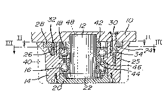
Figure 1, in an axial section, shows the forming
tool in its stop position;
Figure 2 shows the section II-II of Figure l; and
Figure 3 shows the section III-III of Figure 1.
DETAILED DESCRIPTION
The forming tool shown in Figures 1 to 3 has a cap
plate 10 to which a retaining pivot 12, with one of its
ends, is fixed by means of fixing E;crews 48 passing
axially through the retaining pivot 12. An essentially
cylindrical forming body 14 is rotatably mounted on the
retaining pivot 12 by a top and bot:tom radial bearing 16
and 18 respectively. Tangential projections 40 having
the same slope relative to the axis of the forming body
14 are provided on the outer wall of the forming body
14. The outer face of the bottom radial bearing 16 is
held on the one side by an inwardly extending bearing
projec-tion 46 of the forming body 14 and on the other
side by a bearing cap 20 screwed onto the forming body
14 on the side opposite the cap plate 10. The inner
face of the bottom radial bearing 16 is supported on the

2 ~
90--467
one side on a distance ring 44 and on the other side on
a bearing collar 22 provided at the bottom end of the
retaining pivot 12~ The inner face of the top radial
bearing 18 is mounted in a fixed position on the one
side by the distance ring 44 and on the other side by a
distance sleeve 42 which presses with its other side
against the cap plate 10. The outer face of the top
radial bearing 18 rests on the bearing projection 46.
An annular groove 24 which is open at the top
towards the cap plate 10 and is concentric to the
retaining pivot 12 is formed in the forming body 14.
Between the annular groove 24 and the cap plate 10, a
cover ring 28 likewise concentric t:o the retaining pivot
12 is insertad into the orming bocly 14. The surface of
the cover ring 28 is essentially flush with the surface
o~ the forming body 14. The cover ring 28 is connected
to the cap plate via a threaded stem 30 in such a way as
to be fixed in terms of rotation. The cover ring 28 is
dimensioned in such a way that the forming body 14 can
rotate about the retaining pivot 12 and the cover ring
28 without becoming jammed with the latter.
A helical spring 26 is arranged in the annular
groove 24 in such a way that its ends are diametrically
opposite in the stop position of the forming body 14.
One end of the helical spring 26 is connected via a grub
.

~3 ~
90-4~7
screw 32 to the cover ring 28 fixed to the cap plate,
while the other end of the helical spring 26 is
connected to the forming body 14 via a stud bolt 34
screwed into the groove root 25 of the annular groove
24. A stop 38 is provided in the cover ring 28 in the
area of the annular groove 24 diametrically opposite the
helical spring 26, which stop 38 is formed by one end of
a circular ring segment concentric to the retaining
pivot 12. A stop pin 36 fixed to the groove root 25 of
the annular groove 24 engages into the circular ring
segment. The stop pin 36 is preloaded by the tensile
force of the helical spring 26 against the
circular-ring-segment end facing the grub screw 32.
However, the forming body 14 can be rotated against the
tensile direction of the helical sE~ring 26 in such a way
that the stop pin 36 fixed to the forming body 14 moves
in the direction of the circular-segment end opposite
the stop 38, i.e. to the right in Figure 2.
During the pressing of a "green" anode, the forming
tool is inserted into a mold, the mold being closed at
the top by the cap plate 10. After the press operation,
the cap plate 10 is lifted up together with the forming
body 14. On account of the projections 40 running at a
slope on the peripheral wall of the ~orming body 14
relative to its axisr the forming body 14, guided by the
--7--

90-~67
grooves, which have become dimensionally stable during
the pressing, is rotated against the direction of the
tensile force of the helical spring 26, which is thereby
loaded further. As soon as the projections 40 of the
forming body 14 are no longer in contact with the
grooves when the forming body 14 is withdrawn from the
anode, the forming body 1~ is turned back by the
preloaded helical spring 26 until the stop pin 36 bears
against the circular-segment end facing the grub screw
32, i.e. against the stop 38. The forming body 14 is
now again located in its stop position in which the
projections 40 have exactly the same angular position
relative to the new anode to be pressed as in the anode
finished beforehand before the firing.
The helical spring 26 i8 desig;ned to have such a
tensile for~e that the grooves of t~he peg hole, formed
by the forming body 14, are not damaged when the ~orming
body 14 is withdrawn from the anode, and the forming
body 14 is rotated into its stop position after
withdrawal from the anode~.
The exemplary embodiment has been described with
reference to one forming body 14. During the production
of anodes~ however, it is usual to provide at least two
peg holes which are formed in the manner described above
by identical forming bodies 14 rotatably fixed to the
cap plate.
: . ~

Dessin représentatif
Une figure unique qui représente un dessin illustrant l'invention.
États administratifs

2024-08-01 : Dans le cadre de la transition vers les Brevets de nouvelle génération (BNG), la base de données sur les brevets canadiens (BDBC) contient désormais un Historique d'événement plus détaillé, qui reproduit le Journal des événements de notre nouvelle solution interne.

Veuillez noter que les événements débutant par « Inactive : » se réfèrent à des événements qui ne sont plus utilisés dans notre nouvelle solution interne.

Pour une meilleure compréhension de l'état de la demande ou brevet qui figure sur cette page, la rubrique Mise en garde , et les descriptions de Brevet , Historique d'événement , Taxes périodiques et Historique des paiements devraient être consultées.

Historique d'événement

Description Date
Inactive : CIB de MCD 2006-03-11
Le délai pour l'annulation est expiré 1997-12-05
Demande non rétablie avant l'échéance 1997-12-05
Réputée abandonnée - omission de répondre à un avis sur les taxes pour le maintien en état 1996-12-05
Demande publiée (accessible au public) 1991-06-08

Historique d'abandonnement

Date d'abandonnement Raison Date de rétablissement
1996-12-05
Titulaires au dossier

Les titulaires actuels et antérieures au dossier sont affichés en ordre alphabétique.

Titulaires actuels au dossier
ALUSUISSE ITALIA S.P.A.
Titulaires antérieures au dossier
GIOVANNI BISON
Les propriétaires antérieurs qui ne figurent pas dans la liste des « Propriétaires au dossier » apparaîtront dans d'autres documents au dossier.
Documents

Pour visionner les fichiers sélectionnés, entrer le code reCAPTCHA :


Pour visualiser une image, cliquer sur un lien dans la colonne description du document (Temporairement non-disponible). Pour télécharger l'image (les images), cliquer l'une ou plusieurs cases à cocher dans la première colonne et ensuite cliquer sur le bouton "Télécharger sélection en format PDF (archive Zip)" ou le bouton "Télécharger sélection (en un fichier PDF fusionné)".

Liste des documents de brevet publiés et non publiés sur la BDBC .

Si vous avez des difficultés à accéder au contenu, veuillez communiquer avec le Centre de services à la clientèle au 1-866-997-1936, ou envoyer un courriel au Centre de service à la clientèle de l'OPIC.

({010=Tous les documents, 020=Au moment du dépôt, 030=Au moment de la mise à la disponibilité du public, 040=À la délivrance, 050=Examen, 060=Correspondance reçue, 070=Divers, 080=Correspondance envoyée, 090=Paiement})


Description du
Document 
Date
(aaaa-mm-jj) 
Nombre de pages   Taille de l'image (Ko) 
Dessins 1991-06-07 1 40
Abrégé 1991-06-07 2 39
Revendications 1991-06-07 2 39
Description 1991-06-07 7 211
Dessin représentatif 1999-07-18 1 13
Rappel - requête d'examen 1997-08-04 1 117
Taxes 1995-11-29 1 62
Taxes 1994-11-23 1 60
Taxes 1993-11-28 1 53
Taxes 1992-11-11 1 43