Sélection de la langue

Search

Sommaire du brevet 2032591 

Énoncé de désistement de responsabilité concernant l'information provenant de tiers

Une partie des informations de ce site Web a été fournie par des sources externes. Le gouvernement du Canada n'assume aucune responsabilité concernant la précision, l'actualité ou la fiabilité des informations fournies par les sources externes. Les utilisateurs qui désirent employer cette information devraient consulter directement la source des informations. Le contenu fourni par les sources externes n'est pas assujetti aux exigences sur les langues officielles, la protection des renseignements personnels et l'accessibilité.

Disponibilité de l'Abrégé et des Revendications

L'apparition de différences dans le texte et l'image des Revendications et de l'Abrégé dépend du moment auquel le document est publié. Les textes des Revendications et de l'Abrégé sont affichés :

  • lorsque la demande peut être examinée par le public;
  • lorsque le brevet est émis (délivrance).
(12) Brevet: (11) CA 2032591
(54) Titre français: ONGLET POUR CURSEUR DE FERMETURE-ECLAIR
(54) Titre anglais: PULL TAB ASSEMBLY FOR SLIDE FASTENER SLIDER
Statut: Durée expirée - au-delà du délai suivant l'octroi
Données bibliographiques
(51) Classification internationale des brevets (CIB):
  • A44B 19/24 (2006.01)
  • A44B 19/26 (2006.01)
(72) Inventeurs :
  • YUKI, KENJI (Japon)
  • ISHII, SUSUMU (Japon)
(73) Titulaires :
  • YKK CORPORATION
(71) Demandeurs :
  • YKK CORPORATION (Japon)
(74) Agent: GOWLING WLG (CANADA) LLP
(74) Co-agent:
(45) Délivré: 1995-03-28
(22) Date de dépôt: 1990-12-18
(41) Mise à la disponibilité du public: 1991-06-29
Requête d'examen: 1994-04-15
Licence disponible: S.O.
Cédé au domaine public: S.O.
(25) Langue des documents déposés: Anglais

Traité de coopération en matière de brevets (PCT): Non

(30) Données de priorité de la demande:
Numéro de la demande Pays / territoire Date
U.M. 1-152517 (Japon) 1989-12-28

Abrégés

Abrégé anglais


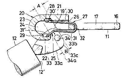
A pull tab assembly for slide fastener slider is
disclosed, which comprises a clamper having at one of its
ends a hook, a resilient member supported in the hook and a
pull tab having a pair of ears which each have such a
geometry that can facilitate mounting and dismounting of the
pull tab with respect to the clamper and further protect the
resilient member against deformation or damage.

Revendications

Note : Les revendications sont présentées dans la langue officielle dans laquelle elles ont été soumises.


CLAIMS
1. A pull tab assembly for slide fastener slider which comprises a
clamper including an arcuate peripheral wall defining therein an aperture and
a transverse bridge linking the confronting ends of said peripheral wall, a hookextending from said confronting ends and having its distal end terminating
short of said bridge so as to define an opening, a resilient member supported
in said hook, and a pull tab provided at one end with a pair of spaced ears
interconnected by a pin, each of said ears having side peripheral walls and an
end surface merging through corners with said side peripheral walls, and each
of said ears having a geometry such that a distance (B) as measured between
one of said peripheral side walls at a point of said peripheral wall adjacent toone of said corners, and a tangent line of said pin parallel with said end surface
and touching the pin at a surface point thereof facing away from said one of
said peripheral side walls is smaller than the width of said opening of said
hook, and that a distance (C) as measured between one of said peripheral side
walls at a point adjoining one of said corners, and a tangent line of said pin
extending at right angles to said end surface and touching the pin at a surface
point thereof facing away from said one of said corners is larger than the widthof said opening.
2. A pull tab assembly according to claim 1 wherein said ears are
spaced apart by a distance substantially corresponding to the width of said
hook.
3. A pull tab assembly according to claim 1 wherein said clamper has
tapered guide surfaces at said confronting ends
4. A pull tab assembly according to claim 1 wherein said pull tab is
in the form of a rod.
5. A pull tab assembly according to claim 1 wherein said pair of ears
diverge toward said clamper and taper off toward said pull tab.

Description

Note : Les descriptions sont présentées dans la langue officielle dans laquelle elles ont été soumises.


203259 1
This invention relates to a pull tab assembly
removably mounted on and adapted to manipulate a slider in
opening and closing a slide fastener.
Prior art and the present invention will be described with
reference to the accompanying drawings, wherein:
FIG. 1 is a plan view of a pull tab assembly embodying
the invention;
FIG. 2 is an exploded, perspective view on enlarged
scale of the assembly;
FIG. 3 is a cross-sectional view of part of the
assembly shown in one operative position;
FIG. 4 is a view similar to FIG. 3 but showing the
assembly in another operative position;
FIG. 5 is a plan view on further enlarged scale of the
pull tab assembly shown in fully assembled condition; and
FIGS. 6, 7 and 8 inclusive are views utilized to
explain the construction and operation of a prior art pull
tab assembly.
The present invention is an improvement in ana
relating to the invention disclosed in U.S. Patent No.
4,920,615 to the same assignee, Yoshida Ko~yo K. K., Tokyo,
Japan.
A slider pull tab disclosed in U.S. Patent No.
4,920,615 is represented in FIGS. 6 - 8 inclusive of the
accompanying drawings and shown comprising a clamper 100

203259 1
pivotally connected to a trunnion 101 on a slider body 102,
a hook 103 extending from one end of the clamper 100 and
having an aperture 104, a resilient member lOS disposed at
the lower portion of the hook 103 and normally closing off
the aperture 104 of the hook 103 and a pull tab 106 having
an annular link 107 for connecting the pull tab 106 to the
clamper 100. While this prior pull tab device has many of
its inherent advantages, it has now been found that the
resilient member 105 is susceptible to deformation leading
to loss of its elastic action, if not to physical damage,
when subjected to pressure exerted by the annular link 107
rotating in contact with the resilient member 105 as for
example in the case of ironing the garment to which the
slide fastener is attached.
It is therefore a primary object of the present
invention to provide an improved pull tab assembly for slide
fastener slider which incorporates structural features
tailored to eliminate the foregoing drawbacks of the prior
art.
More specifically, the pull tab assembly according to
the invention includes means of maintaining a pull tab out
of contact with a resilient member even when the pull tab is
oriented to underlie a clamper.
The pull tab assembly according to the invention
further includes means of facilitating connection and
disconnection of the pull tab with respect to a clamper.

~- 203259 1
The pull tab assembly of the invention also includes
means of preventing undue lateral rocking movement of the
pull tab.
According to the invention, there is provided a pull
tab assembly for slide fastener slider which comprises a
clamper including an arcuate peripheral wall defining
therein an aperture and a transverse bridge linking the
confronting ends of the peripheral wall, a hook extending
from the confronting ends and having its distal end
terminating short of the bridge so as to define an opening,
a resilient member supported in the hook, and a pull tab
provided at one end with a pair of spaced ears
interconnected by a pin, each of the ears having side
peripheral walls and an end surface merging through corners
with the side walls, and each of the ears having a geometry
such that a distance as measured between the end surface and
a tangent line of the pin extending in parallel with the end
surface is smaller than the width of the opening of the hook
and that a distance as measured between the side wall
adjoining the corner and a tangent line of the pin extending
at right angles to the end surface is larger than the width
of the opening.
The above and other features and advantages of the
present invention will appear clear from the following
detailed description taken in conjunction with the
accompanying drawings which illustrate by way of example a
preferred embodiment.

- 203259 1
Referring now to the drawings and firstly FIG. 1,
there is shown a pull tab assembly 10 which comprises a
clamper 11 and a pull tab 12 releasably connected thereto by
a hook 20, the clamper 11 being pivotally connected to a
connecting lug or trunnion 14 on a slider body 15 in a well
known manner.
As better shown in FIG. 2, the clamper 11 includes an
arcuate peripheral wall 16 defining therein an aperture 17
through which the trunnion 14 of the slider body 15 is
loosely fitted for pivotal connection of the clamper 11 and
a transverse bridge 18 linking the confronting ends 16', 16'
of the arcute peripheral wall 16, at which ends are formed
shoulders 19, 19 having respective tapered guide surfaces
19', 19'. A hook 20 formed integral with the arcuate
peripheral wall 16 has an upper straight wall 21 extending
integrally from the confronting ends 16', 16' of the arcuate
peripheral wall 16, a lower straight wall 22 and an arcuate
wall 23 integrally interconnecting the upper and lower walls
21 and 22 and defining therewith a substantially U-shaped
aperture 24 extending transversely of the pull tab body 12.
The lower wall 22 of the hook 20 has its distal end
terminating short of the transverse bridge 18 so as to
define an opening 25 communicating with the aperture 24 and
adapted to bring the clamper 11 into and out of engagement
with the hook 20. The upper wall 21 of the hook 20 is

203259 1
raised above the level of the arcuate peripheral wall 16 so
as to define an opening 26 through which a resilient member
27 is mounted in place in a manner hereafter described.
The hook 20 has a first recess 28 formed in the inner
surface of the upper wall 21 and a second recess 29 formed
in the distal end of the lower wall 22 for receptive
engagement with the resilient member 27 as better shown in
FIGS. 3 and 4.
The resilient member 27 thus supported in the hook 20
is in the form of a substantially U-shaped leaf spring which
has an upper arm 30 and a lower arm 31 merged together by an
arcuate joint 32. The upper arm 30 is provided at its
distal end with an upwardly projecting claw 30', and the
lower arm 31 is provided at its distal end with a downwardly
slanted finger 31'.
The claw 30' and the finger 31' are snappingly
received in and retained at the first recess 28 and the
second recess 29, respectively, of the hook 20, with the
arcuate joint 32 held in surrounding relation to the
transverse bridge 18 of the clamper 11 as better shown in
FIGS. 3 and 4.
The pull tab body 12 is in the form of a rod provided
at one end 12' with a pair of ears 33, 33 diverging toward
the clamper 11 and interconnected by a transverse pin 34
with which to displace the lower arm 31 of the resilient
member 27 inwardly out of engagement with the second recess
29 of the hook 20 so as to engage the pull tab 12 with the

203259 1
clamper 11 as shown in FIGS. 3 and 4. The ears 33, 33 each
have side peripheral walls 33a, 33a tapering off toward the
pull tab end 12' and a substantially straight end surface
33b merging through rounded corners 33c, 33c with the side
walls 33a, 33a. The ears 33, 33 are spaced apart by a
distance substantially corresponding to the width of the
hook 20 such that the pull tab 12 once connected to the
clamper 11 is retained in place against lateral
displacement.
The provision of the guide surfaces 19', 19' being
tapered facilitates smooth sliding movement therealong of
the ears 33, 33 of the pull tab 12 into the aperture 24 of
the hook 20.
According to an important aspect of the invention,
each of the ears 33, 33 has a geometry such that a distance
B as measured between the end surface 33b and a tangent line
34a of the pin 34 extending in parallel with the end surface
33b is smaller than the width A of the opening 25 of the
hook 20 and that a distance C as measured between the side
peripheral wall 33a adjoining the corner 33c and a tangent
line 34b of the pin 34 extending at right angles to the end
surface 33b is larger than the width A of the opening 25 of
the hook 20, as depicted in FIGS. 3 and 4. This geometric
concept contributes to a maximum of ease with which to mount
and dismount the pull tab 12 with respect to the clamper 11
and at the same time precludes the possibility of the pin 34
of the pull tab 12 jamming against and injuring the

- 2032S9 1
resilient member 27 even in the event the pull tab 12 is
flipped down to undlie the clamper 11 as shown in FIG. 4.
Obviously, various modifications and variations of the
present invention are possible in the light of the above
teaching. It is therefore to be understood that within the
scope of the appended claims the invention may be practiced
otherwise than as specifically described.

Dessin représentatif
Une figure unique qui représente un dessin illustrant l'invention.
États administratifs

2024-08-01 : Dans le cadre de la transition vers les Brevets de nouvelle génération (BNG), la base de données sur les brevets canadiens (BDBC) contient désormais un Historique d'événement plus détaillé, qui reproduit le Journal des événements de notre nouvelle solution interne.

Veuillez noter que les événements débutant par « Inactive : » se réfèrent à des événements qui ne sont plus utilisés dans notre nouvelle solution interne.

Pour une meilleure compréhension de l'état de la demande ou brevet qui figure sur cette page, la rubrique Mise en garde , et les descriptions de Brevet , Historique d'événement , Taxes périodiques et Historique des paiements devraient être consultées.

Historique d'événement

Description Date
Inactive : Périmé (brevet - nouvelle loi) 2010-12-18
Inactive : CIB de MCD 2006-03-11
Accordé par délivrance 1995-03-28
Toutes les exigences pour l'examen - jugée conforme 1994-04-15
Exigences pour une requête d'examen - jugée conforme 1994-04-15
Demande publiée (accessible au public) 1991-06-29

Historique d'abandonnement

Il n'y a pas d'historique d'abandonnement

Historique des taxes

Type de taxes Anniversaire Échéance Date payée
TM (brevet, 7e anniv.) - générale 1997-12-18 1997-11-06
TM (brevet, 8e anniv.) - générale 1998-12-18 1998-09-16
TM (brevet, 9e anniv.) - générale 1999-12-20 1999-09-08
TM (brevet, 10e anniv.) - générale 2000-12-18 2000-09-21
TM (brevet, 11e anniv.) - générale 2001-12-18 2001-11-19
TM (brevet, 12e anniv.) - générale 2002-12-18 2002-11-19
TM (brevet, 13e anniv.) - générale 2003-12-18 2003-11-17
TM (brevet, 14e anniv.) - générale 2004-12-20 2004-11-08
TM (brevet, 15e anniv.) - générale 2005-12-19 2005-11-08
TM (brevet, 16e anniv.) - générale 2006-12-18 2006-11-08
TM (brevet, 17e anniv.) - générale 2007-12-18 2007-11-09
TM (brevet, 18e anniv.) - générale 2008-12-18 2008-11-10
TM (brevet, 19e anniv.) - générale 2009-12-18 2009-11-12
Titulaires au dossier

Les titulaires actuels et antérieures au dossier sont affichés en ordre alphabétique.

Titulaires actuels au dossier
YKK CORPORATION
Titulaires antérieures au dossier
KENJI YUKI
SUSUMU ISHII
Les propriétaires antérieurs qui ne figurent pas dans la liste des « Propriétaires au dossier » apparaîtront dans d'autres documents au dossier.
Documents

Pour visionner les fichiers sélectionnés, entrer le code reCAPTCHA :


Pour visualiser une image, cliquer sur un lien dans la colonne description du document (Temporairement non-disponible). Pour télécharger l'image (les images), cliquer l'une ou plusieurs cases à cocher dans la première colonne et ensuite cliquer sur le bouton "Télécharger sélection en format PDF (archive Zip)" ou le bouton "Télécharger sélection (en un fichier PDF fusionné)".

Liste des documents de brevet publiés et non publiés sur la BDBC .

Si vous avez des difficultés à accéder au contenu, veuillez communiquer avec le Centre de services à la clientèle au 1-866-997-1936, ou envoyer un courriel au Centre de service à la clientèle de l'OPIC.


Description du
Document 
Date
(yyyy-mm-dd) 
Nombre de pages   Taille de l'image (Ko) 
Page couverture 1995-03-27 1 17
Abrégé 1995-03-27 1 12
Description 1995-03-27 7 211
Abrégé 1995-03-27 1 12
Dessins 1995-03-27 4 81
Revendications 1995-03-27 1 43
Dessin représentatif 1998-06-29 1 13
Taxes 1992-10-06 1 55
Taxes 1994-11-21 1 80
Taxes 1996-11-14 1 73
Taxes 1995-10-31 1 77
Taxes 1993-10-20 1 82
Demande de l'examinateur 1994-01-06 1 51
Correspondance de la poursuite 1994-04-14 1 27
Courtoisie - Lettre du bureau 1995-04-19 1 364
Correspondance reliée aux formalités 1994-10-30 1 41
Correspondance de la poursuite 1993-07-13 2 36
Courtoisie - Lettre du bureau 1991-06-11 1 23
Courtoisie - Lettre du bureau 1995-03-30 1 41
Demande de l'examinateur 1993-01-25 1 52
Correspondance de la poursuite 1990-12-17 5 166