Note : Les descriptions sont présentées dans la langue officielle dans laquelle elles ont été soumises.
21( 3~2
-- 1 --
BACRG~OUND OF THE INVENTION
a) Field of the invention
The present invention relates to a method for
sorting objects such as bottles or containers, at least two
different transparent or translucent pla5tic materials,
according to the kind of plastic materia~s these objects
are made of.
The invention also relates to an apparatus for use
to carry out this method.
b) Brief description of the prior art
It is known that a very large number of plastic
bottles or containers are sold and disposed off every day
throughout the world. Because these reject plastic bottles or
containers are not biodegradable, they constitute a substantial
source of pollution.
It has already been suggested to recover the
plastic materials of which they are made, which materials are
usually P.V.C., P.E.T. (polyester), polystyrene, polypropylene
or polyethylene, in view of recycling them. The major problem
however with such a recovery is that, on the one hand, it is
very difficult to distinguish most of the existing plastic
materials from each other and that, on the other hand, P.V.C.,
P.E.T., polyethylene and polypropylene must be separated from
each other to make their recycling possible and economically
viable.
Accordingly, there is presently a great need for
a method for use to sort reject plastic bottles or containers
according to their plastic compositions, in order to
separate, for example, P.V.C. bottles or containers from P.E.T.
and other plastic bottles or containers, and thus make
recycling of these rejects possible.
- ~ ~
--- 2~3~ 2
Different methods and apparatus are presently being
known, for use to sort objects made of different transparent
or translucent materials according to the kind of material of
which they are each made.
By way of example, U.S. patent No. 4,919,534
granted to ENVIRONMENTAL PRODUCTS CORP. discloses an apparatus
for sorting bottles made of transparent material, i~ view of
separating those made of plastic material, especially P.E.T.,
from those made of glass. The differentiation between glass and
plastic is achieved by optical means whose operation derives
from the fact that glass does not affect the polarization of
a beam of light passing therethrough, contrary to plastic which
does affect the polarization of such a beam. The apparatus
disclosed in this patent No. 4,919,534 is certainly efficient
to differentiate glass from any kind Of plastic material.
Ho~r, it ~ of no use to differentiate different plastic
materials from each other.
U.S. patent No. 4,663,522 to 5PANDREL
ESTABLISHEMENT discloses an apparatus for detecting the kind
of material of which an object is made, which comprises optical
means for measuring the intensity of the radiations scattered
in a forward direction into one or more conceptual hollow cones
of appropriate angles when the object to be sorted is subjected
to a light beam.
U.S. patent Nos. 3,802,558 to SORTEX COMPANY OF
NORTH AMERICA INC. and 4,513,868 to GUNSON'S SORTEX LTD. both
disclose an apparatus for sorting particles such as glass
beads, grains of rice, and the like, which comprises optical
means to measure the ability of each particle to transmit,
reflect or emit visible light in a predetermined part of the
spectrum. In U.S. patent No. 4,513,868, sorting is carried out
by detection of light coming from the object and having any
undesired character. In U.S. patent No. 3,802,558, sorting is
carried out according to the transparency and the color of the
particles. None of these patents suggests that it is possible
to use the apparatus disclosed therein to sort different kinds
.
:;
, . . .
. . ,, ~
--
.
.. . , , . - .
- - , .
,:, . ; ~ .
2~ 7~
--3--
.
of plastic materials.
As of interest also are U.S. patent Nos. 3,067,862
to ANCHOR HOCKING GLASS CORPORATION and 4,379,636 to HAJIME
INDUSTRIES LT~., which both disclose an apparatus for
inspectiny objects in order to detect defects therein. Both of
these documents comprise optical means to measure light
refraction, diffraction and/or diffusion of each object to be
inspected, when this object is subjected to a beam of light.
None of them however are directed to the sorting of objects
made of different materials, and more particularly objects made
of different plastic materials.
OBJECTS AND SUMMARY OF THE INVENTIoN
An object of the present invention is to provide
method for sorting objects made of different transparent or
translucent plastic material according to the kind of plastic
materials these objects are made of, which method is very
simple and efficient, very easy to scale up for operation in
an industrial scale, and particularly well adapted for
sorting bottles or containers made of P.V.C., P.E.T. and other
conventional plastic materials, in view of recycling them.
Another object of the present invention is to
provide an apparatus for carrying out this method, which
apparatus is essentially optical and made of readily available
components, which does not contain any moving elements and is
of a low cost to manufacture, aside which, whenever desired,
can be easily connected to a mechanical or pneumatical sorting
device to cause automatic sorting of the objects being
processed according to the kind of plastic material they are
made.
The machine, method and apparatus according to the
invention are essentially optical and take advantage of a
"natural" property of any transparent or translucent plastic
material, namely to have a specific wavelength in the U.V.
band, called "cut-off wavelength", above which the coefficient
:
2~7~2
of light transmission of the material dramatically increases
when this material is subjected to a beam of light. The cut-
off wavelength where such a "step" in light transmission may
be noticed is quite different from one plastic material to
another and can be said to be specific to each kind o~ plastic
material although there can be some variations in the value of
the cut-off wavelength of a given plastic material depending
on some factors, such as the thickness of this material. ~ -
In the following table, typical cut-off wavelengths
of different transparent or translucent plastic materials
commonly used in the industry are given, together with some
examples of products available on the market, which are made
of such plastic materials.
TABLE
Plastic material typical cut-off examples of products
wavelength (nm) made of such material
polyethylene 192 ZIPLOC bag, bottle
of milk
polystyrene 280 pill box
natural P.V.C. 302 bottles of CRISCO
oil or WINDEX
P.E.T. 315 bottles of COCA-
COLA, PEPSI,
LISTERINE or NAYA
water
W -protected P.V.C. bottles of VICHY or
340 LABRADOR water
.:
green P.E.T. 400 bottles of CANADA
DRY, SEVEN UP, SPRITE
: . .:,, - - ~ -
-,
. : . - . . . .
As aforesaid, the method and apparatus according
to the invention take advantage of this cut-off wavelength
property to detect the kind of plastic material from which are
made objects such as reject bottles or containers, passing
between a source of U.V. light and detecting means that may
consist of a set of sensors each adjusted to a given wavelength
and if desired, to sort the objects as a function of the
transmission signal(s) detected by the sensors.
In practice, the sensors may be adjusted to give
signals indicative of light transmission at different
increasing wavelengths. If, for example, bottles of natural
P.V.C. and polyethylene have to be sorted, use can be made of
a first sensor adjusted to any value between 192 ar.d 302 nm,
say 200 nm, to differentiate between these two plastic
materials provided however that there are no opaque bottles.
Indeed, any signal indicative of some light transmission given
by the first sensor will indicate that the bottle being sensed
is made of polyethylene. If no signal indicative of some light
transmission is given by the first sensor when a bottle
intersects the beam, this will indicate however that the bottle
being sensed is made of natural P.V.C. Of course, other
sensors may be used in combination with the first sensor to
detect the presence or absence of bottles and to normalize the
signals.
As aforesaid, a mechanical or pneumatic sorting
device can be connected to the apparatus. This device may
consist of blowers activable to push the object being sensed
into a given bin as is known from U.S. patent Nos. 3,802,558;
4,513,868 or 4,663,522, or of flaps or baffles to mechanically
direct the object into a given chute.
Since the differentiation between the different
plastic materials is made by determination of the coefficient
of transmission of these materials, it is obvious that the
objects to be sorted must be transparent or translucent within
the range of U.V. wavelengths where the measurement is carried
out.
--- 2~7~
The apparatus and method according to the invention
can be devised however to make it possible to identify as such
any opaque material, such as metal or opaque plastic, and to
sort it out.
More particularly, the present invention as broadly
claimed hereinafter is directed to an apparatus for sorting
objects made of at least two different transparent or
translucent plastic materials according to the kind of plastic
materials these objects are made of, each of these different
plastic materials having a light transmission coefficient which
dramatically increases above a given wavelength in the U.V.,
such a given wavelength known "per se" being called the "cut-
off wavelength" and being a characteristic of the plastic
material, the apparatus comprising:
- means to produce a beam of U.V. light; and
- detecting means spaced apart from the beam
producing means and positioned to receive the U.V. light beam,
the detecting means giving signals proportional to the
intensities of the received beam at different wavelengths
selected within a range encompassing the known cut-off
wavelengths of the different plastic materials,
whereby, in use, each object to be sorted is
inserted between.the beam producing means and the detecting
means in such a manner as to intersect said U.V. light beam and
the signals given by the detecting means at said different
wavelengths are compared with each other to determine the cut-
off wavelength of the ~lastic material of which said inserted
object is made, and thu's to identify this plastic material.
The present invention as broadly claimed
hereinafter is also directed to a method for sorting objects
made of at least two different transparent or translucent
plastic materials according to the kind of plastic materials
these objects are made of, each of these different plastic
materials having a light transmission co~ficient which
dramatically increases above a given wavelength in the U.V.,
such a given wavelength known ~er se being called the "cut-off
: :'
:: -,
: . : . , :,: . ....... : : :
~3~
wavelength~' and being a characteristic of the plastic material,
which method comprises the steps o~:
~ producing a beam of U.V. light;
- subjecting each object to be sorted to this beam
in a detection zone;
- detecting the intensities of the beam transmitted
by the object in the detection zone at different wavelengths
selected within a range encompassing the known cut-off
wavelengths of the different plastic materials, and
- comparing with each other the intensities
detected at said different wavelengths to determine the cut-
off wavelength of the plastic material of which the object
subjected to the beam is being made, in order to identify this
plastic material.
BRIEF DESCRIPTION OF THE ~RAWINGS
Other objects, advantages and applications of the
present invention will be better understood upon reading of the
following, non restrictive general description of the
invention, given with reference to the accompanying drawings
in which:
Fig. 1 is a curve giving the coefficient of light
transmission of different plastic materials as a function of
wavelengths ranging from 270 to 360 nm and showing how one can
determine the cut-off wavelengths of these different plastic
materials in view of differentiating them; and
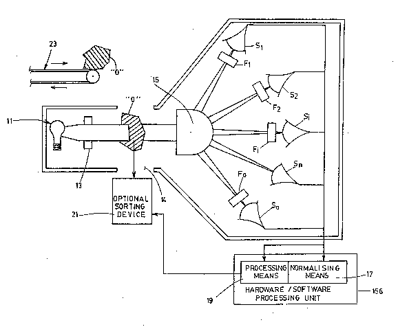
Fig. 2 is a block diagram of an example of
apparatus according to the invention.
GENERAL DESCRIPTIÇN OF TH~ INVENTION
The apparatus according to the invention as shown
in Fig. 2 is intended to be used for sorting objects made of
a number "n" of different transparent or translucent plastic
materials according to the kind of plastic material of which
each of the objects to be sorted is being made, such as P.V.C.,
W -protected P.V.C., polystyrene, polyethylene, polypropylene
or P.E.T. As was explained hereinabove, each of these n
different plastic numbered 1, 2...i... n in Fig. 1 has a light
--8--
transmission coefficient which dramatically increases above a
given wavelength in the U.V. This given wavelength which is
called the "cut-off wavelength" and identified as ~ 1~
~ n in Fig. 1, is a characteristic of each
plastic material.
Basically, the apparatus according to the invention
comprises means to produce a beam of U.V. light and detecting
means spaced apart from the beam producing means and positioned
to receive the U.V. light beam. The beam producing means
includes a U.V. light source 11 and a beam conditioning device
13 known per se, which are both selected to generate a beam
partly composed of U.V. light, made up of wavelengths ranging
from, say, 150 to 1,000 nm. The detecting means whose function
is to give signals proportional to the intensity of the
received beam at different wavelengths recited within a range
encompassing the cut-off wavelengths of the different plastic
materials, may comprise:
- means 15 to split the received light beam into
a plurality of sub-beams;
- means Fo~ F~, F,... F1..., that may consist of
interferential filters, gas cells or dispersion elements, to
filter each of these sub-beams at one given wavelength
different from the wavelengths at which the other sub-beams are
filtered; and
- a light intensity sensor or detector S0, S1, S2,
S~... Sn associated to each of the filtering means to give a
signal proportional to the intensity of the sub-beam filtered
~y the associated filtering means.
Advantageously, the splitting means 15 is adapted
to produce a number of sub-beams at least equal to the number
"n" of different plastic materials to be identified, plus one.
one of the filtering means hereinafter called "first filtering
means" which is identified as Fo in Fig. 2, is also adapted to
filter the sub-beam it receives from the splitting means 15 at
a wavelength which is lower than the lowest cut-off wavelength
of the different plastic materials to be identified. In
:
. . . , ~ . . :
. : . . . , ~ - - ,
3~ ~ ~
operation, the signal given by the detector Do associated to
the first filtering means Fo is used as an indication of the
presence or absence of an object to be sorted intersecting the
U.V. light beam.
Anoth~r filtering means hereinafter called "second
filtering means", is adapted to filter the su~-beam it receives
from the splitting means 15 at another wavelength which is
higher than the highest cut-off wavelength of the different
plastic materials to be identified, in order to produce, via
the associatd detector, a normalization signal.
The wavelength at which this second filtering means
is adapted to filter the sub-beam it receives from the
splitting ~eans 15 to produce the normalization signal, may in
practice be a wide band of wavelengths whose upper limit is
higher than the highest cut-off of the plastic material to be
detected. This wide band of wavelengths may, in fact, be so
wide as to encompass all the band of emission of the light
source 11 therefore making it unecessary to use a filtering
element of physical structure as second filtering means, as is
shown in Fig. 2 where the associated detector is identified as
sn.
The remaining filtering means F1, F, --- F1 ....
F~l are advantageously adapted to fil~er the sub-beams they
receive from the splitting means 15 at further wavelengths
which are respectively comprised between the various pairs of
adjacent cut-off wavelengths to be determined.
In practice, the wavelengths at which the first and
each of the remaining filtering means Fo~ Fl,... F1... are
adapted to filter the sub-beams they receive from the splitting
means 15, consist of narrow bands of wavelengths of, typically,
from S to 10 nm, hereinafter called ~ ~O,~l,a ~2~ which
are respectively centered on the wavelengths of the first and
other filtsring means, as is shown in Fig. 1.
All the detectors SO, S" S"... S1... Sn are
connected to a hardware/software processing unit 16 comprising
means 17 known ~er se for use, to normalize the signals
received from all t.he detectors with the normalization signal
' ':' ~ . ;:; : .~
: . ' -- '
~, :
: . :: :-, . ., , :
; ~ ., . ;~ - ., ~
2 ~
--10--
received from the detector Sn associated to the second
filtering means. The basic purpose of this normalization is to
take into account any variation in the opacity of the objects
to be sorted, or any lack of uniformity between these objects
as will be better explained hereina~ter. The processing unit
16 also comprises processing means 19 operatively associated
to the normalization means 17 and acting in feedback on all of
the detectors. These processing means are devised to
synchronize the operation of these detectors when the signal
given by the detector 50 associated to the first filtering
means Fo indicates that an object is intersecting the U.V.
light beam. These processing means are also devised to process
the normalized signals received from the normalization means
as will be explained hereinafter, to give a processed signal
indicative of the kind of plastic material of which is made the
object intersecting the U.V. light beam.
This processed signal can be displayed in any form,
i.e. visual or sonorous for us, for "use" by a human operator.
However, thiæ processed signal is preferably used to control
optional discarding means in the form of a sorting device 21
that can be mechanical and make use of baffles or flaps
controllably pistons or solenoids, or be pneumatic and make use
of valve-controlled, air nozzles connected to a pressurized air
source, to "push" the object "O" leaving the detection zone 14
into a bin, container or chute corresponding to the kind of
plastic material of which this object is made.
The discarding means 21 are therefore connected to
the processing means 19 and responsive to the processed signal
givey by this processing means 19 to selectively discard the
objects ~0" to which processed signals corresponds, into bins
corresponding to the kinds of plastic material of which these
objects are made.
In use, the apparatus can be made automatic and
used to sort many objects per second, provided they are fed at
sufficient speed into the detection zone 14. To do so,
: . , i . ~ . , : . . . , :
:
- . ,, , .. ,, :
~ ~ ~ 'ç``~
conveying means 23 can be provided for mechanically bringing
the objects "O" to be sorted between the beam producing means
and the detecting means, so that these objects successively
intersect the light beam and be sorted when they leave the
detection zone 14.
As was explained in the preamble of the present
disclosure, the apparatus according to the invention is
particularly well adapted to sort bottles made of at least two
different plastic materials selected from the group consisting
of polyethylene, polystyrene, PVC, PET, W-resistant PVC and
green PET.
As was also explained hereinabove, each plastic
material comprises a "cut-off wavelength"which is known, easily
determinable and specific to it and under which the coefficient
of transmission is almost equal to O. In Fig. 1, these cut-off
wavelengths are identified as ~ "... ~ "... and A n; the
wavelengths increasing with increasinq values of indices.
A narrow band of wavelength ~ L can be
associated to each pair of plastic materials such as materials
i-l and i whose cut-off wavelengths~ and ~ , are adjacent.
This band ~ ~ 1, is located between the cut-off wavelengths
-l and ~1 in such a manner that ~ ~ is higher than
-l but lower than ~ 1~
As can be understood, there will always be a band
of wavelengths ~ ~1l i being an integer ranging between 1 and n,
to which all of the plastic materials whose cut-off wavelengths
are higher than ~ will remain opaque. If the object to be
sorted does not transmit light as explained hereinabove based
on the definition of the cut-off wavelength within the narrow
range ~ this object will necessarily be made of one of the
materials i + 1, i + 2,... or n.
This, by way of example, if there is no
transmission detected in the narrow range ~ ~n-l~ the object is
made of material n. If however, the object does not transmit
ligth in the range ~ n-~ the object is made of either material
n - 1 or material n. One may then determine of which one of
- . :
. : ~
:
2 s3' ~ ~J a ~3 ~
-12-
these two materials the object to be sorted is being made, by
checking whether the object transmits ligtht in the immediately
higher range a ~ n-l -
As aforesaid, the processing means 19 receives andprocesses all the signals coming from the detectors SO, Sl
...Sl... Sn which signals are each associated to a range of
wavelengths ~ ~0, ~ ~ n-l . The algorithm used in the
processing means 19 is adapted to find the first range of
wavelengths, say ~ A 1 (starting with the highest i and
decreasing), where the object subjected to the U.V. light beam
does not transmit light. Of course,mater;~l of which the
object is made is the one whose cut-off wavelength is
immediately superior to this range~ ~1
In practice, the objects subjected to the beam may
have different shapes, thickness, texture, uniformity, etc.,
especially when these objects are rejects. To take into account
these variations, a plurality of readings can be made at
different locations of every object while the same is moving
across the light beam, and all these readings can be correlated
for validation purposes, the kind of material of which the
object is made being actually determined from a statiscal
evaluation on all these readings.
In order to further improve the efficiency of the
device, all the intensities that are detected by all the
detectors within the measurement ranges ~0, ~
and a ~ n can be normalized with the signal received from the
detector Sn which is preferably adapted to work on a broad
range of wavelengths encompassing the cut-off wavelengths of
all the plastic materials to be identified.
As can be understood, n - 1 of the n + 1 detectors
are used to identify the n materials forming the objects to be
sorted. The remaining detectors are those identified as SO and
Sn in the drawings. Detector Sn gives a signal that is used for
normalizing the signals from the other detectors. Detector SO
gives a signal corresponding to the transmitted intensity in
the narrow range ~ ~0 which is lower than the lowermost cut-
- ~ : ~ . :: . : -
,', . , - , ,
~:- ' ~ : ,
:: ~
~g~t3~ L~ ~
off wavelengtb of the different plastic material to be
identified. The purpose of this detector SO is essentially to
detect whether or not there is an object int~ectiDg the light beam
where the measurements of the other detectors are being made.
Indeed, the detector S0 will never give a signal if there is an
object intersecting the beam, since all the materials of which
these objects are made, "read" as being opaque in the ~ ~0
range. Of course, this particular property can also be used for
synchronizing the operation of all the detectors as was
explained hereinabove.
In order to provide permanent updating of the
apparatus and take into account any variation in the intensity
of the light source 11, correcting means (not shown) may be
incorporated into the electronic of the apparatus. These
correction means can use one or more detectors and be
programmed to make readings and corrections whenever necessary,
during the short intervals when there is no object intersecting
the light beam.
Example
An apparatus according to the invention as
disclosed hereinabove was devised and tested for sorting
bottles made of PVC and PET, respectively. This apparatus
comprised a mercury light source (ORIEL~ No. 6513), a lens
acting as beam conditioning device 13, a fused silica window
acting as beam splitter 15, a pair of filters centered around
300 and 334 nm and three detectors consisting of U.V. enhanced,
5;l;con photodiodes.
The U.V. light beam ~ erated by the light source had
a portion of it that passed through the window 15 and the 334
nm interferential filter before reaching the first one of the
three detectors. This 334 nm interferential filter had a
reflecting surface oriented toward the source, so that a
portion of the beam was reflected via the window towards the
second detector, wi.th no wavelength filtration.
Another portion of the original beam was reflected
~y the window acting as beam splitted towards the third
'
-
.
.
-14-
detector that was located behind the 300nm, interferential
filter, the latter filter also having a reflecting surface
facing the window so that part of the beam was reflected
towards the second detector with no filter.
This particular arrangement made it possible to
split the original beam in three different sub-beams without
too much loss in energy.
The detector receiving the signal filtered at 300
nm was used for the detection of the presence or absence of the
bottles within the detection zone. The detector associated to
334 nm filter was used to differentiate PVC from PET. Last of
all, the third detector with no filter was used to correct all
the signals and take into account the variations in opacity
of the objects that were subjected to sorting. This last
detector was also used to distinguish the bottles that were not
made of PVC or PET from those that were to be actually sorted.
Tests were carried out with this apparatus at a
spead of 25 readings per object to be sorted while the objects
were moving down within the detection zone. Such a speed
allowed full analysis the materials of which each bottle was
made since all of these bottles were about 30 cm bng. The
results that were obtained were excellent and sorting of the
bottles of W -protected PVC from those made of PET was actually
carried out in real time.