Note : Les descriptions sont présentées dans la langue officielle dans laquelle elles ont été soumises.
;~0~ 6
A ~ALVE AND MEMBRANE DEVICE
Membrane cells are used in chemical analysis to parti-
tion a sample contained on one side of a membrane from a
compartment positioned on the other side of the membrane.
The sample contains a component of interest that permeates
through, i.e., across, the membrane into the compartment.
The permeated component of interest in this compartment can
then be analyzed. If the sample contains another component
that does not permeate through the membrane which otherwise
would interfere with the analysis of the component of
interest, then the use of a membrane cell in the analysis of
the component of interest is beneficial.
Membrane cells can use sheet type membranes or tubular
type membranes. A cell using a sheet type membrane can be
made by clamping the membrane between two housing portions,
each portion having a cavity exposed to the membrane. The
cavities are in a juxtaposed position such that they face
the membrane. A sample containing a component of interest
is placed in one of the cavities. The component of interest
permeates through the membrane into the other cavity. The
contents of the other cavity are then analyzed for the
permeated component of interest. A cell using a tubular
type membrane can be made by sealing the outer end portions
of a tubular membrane to the inner end portions of a metal
tube leaving an annular space between the central portion of
the inside of the metal tube and the central portion of the
outside of the tubular membrane. A sample containing a
component of interest can be placed in the annular space.
37244-F -l-
- - -
~ 3
The component of interest permeates through the membrane
into the bore of the membrane. The contents of the bore of
the membrane are then analyzed for the permeated component
of interest. Conversely, the sample can be placed in the
bore of the tubular membrane and the contents of the annular
space can be analyzed.
One important application of membranes in chemical
analysis is in the field of mass spectrometry. The membrane
of a membrane cell is used to partition a sample from the
vacuum inlet of a mass spectrometer. A component of
interest of the sample placed on one side of the membrane
permeates across the membrane, passes into the partial
vacuum on the other side of the membrane as a gas or vapor
and is flowed into the mass spectrometer for analysis.
Usually, a valve is placed in the vacuum line between the
membrane cell and the mass spectrometer so that passage of
the component of interest into the mass spectrometer can be
stopped if desired. Frequently, several membrane cells are
connected to a mass spectrometer through such valves so that
each can be respectively analyzed in turn. It would be an
advance in this art if the valve and the membrane cell could
be combined into one device to reduce the number of
apparatus components needed.
The present invention resides in a valve and membrane
device, comprising: (a) a semipermeable membrane having a
first side and a second side; (b) a valve body defining a
cavity therein, said cavity being partitioned by the
membrane into a first cavity portion exposed to said first
side of said membrane and a second cavity portion exposed to
said second side of said membrane, said valve body having
first, second and third passageways extending thereinto,
said first and second passageways opening into said first
cavity portion, said third passageway opening into said
second cavity portion for flow of a fluid through said first
passageway into said first cavity portion and then through
said second passageway and for permeation of a fluid
37244-F -2-
Z~3Z!3~6
component across said membrane into said second cavity
portion for flow out of said valve body through said third
passageway; and (c) means positioned within said cavity for
controlling the flow of said fluid component through said
third passageway.
When used in a mass spectrometry system, the third
passageway is connected to the vacuum inlet of the mass
spectrometer. A sample is flowed into the first passageway,
into the first cavity portion, where it comes into contact
with the membrane, and is then passed out the second
passageway. ~hen the third passageway is open, a component
of the sample that has permeated across the membrane into
the second cavity portion flows as a gas or vapor into the
vacuum inlet of the mass spectrometer.
Fig. 1 is a cross-sectional side view of a device
according to the present invention, the device incorporating
a sheet type membrane;
Fig. 2 is a cro5s-sectional top view of the device shown
in Fig. 1 when taken along section line 2-2 of Fig. l;
Fig. 3 is a cross-sectional side view of a device
according to the present invention, the device incorporating
a tubular membrane;
Fig. 4 is a cross-sectional top view of the device shown
in Fig. 3 when taken along section line 4-4 of Fig. 3;
Fig. 5 is a cross-sectional enlarged side view of one
means of sealing a tubular membrane to the body of the
device;
Fig. 6 is a cross-sectional enlarged side view of
another means of sealing a tubular membrane to the body of
the device.
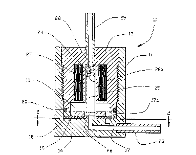
Referring now to Figs 1 and 2, therein is shown a valve
and membrane device 10 comprising a housing 11 and a plug
12. The housing 11 and the plug 12 are provided with mating
threads as shown. The housing 11 and the plug 12 form the
body of the device 10 and define a cavity 13 therein. The
37244-F -3-
~&~ 6
housing 11 and the plug 12 are preferably made from stain-
less steel but can be made of almost any other suitable
material such as another metal, a ceramic or a polymer. The
housing 11 has a circular channel 14 machined in a bottom
portion. However, the geometry of the channel is not
critical and it could be in a spiral shape, a zigzag shape,
a rectangular or other shape. The housing 11 has a first
passageway 15 from the exterior of the housing 11 to one end
of the channel 14 and a second passageway 16 from the
exterior of the housing 11 to the other end of the channel
14. The housing 11 further has a third passageway 17
extending from the exterior of the housing 11 to the chamber
13. A washer 17a and a sheet membrane 1~ are sandwiched
between the plug 12 and the housing 11. A series of holes
19 are drilled in the washer 17a opposite the channel 14~
An O-ring 20 seals the washer 17a, the housing 11 and the
plug 12. One side of the membrane 18 is thus exposed to the
chamber 13 via the holes 19 in the washer 17a while the
other side of the membrane 18 is exposed to the channel 14.
The plug 12 presses against the washer 17a which in turn is
pressed against the membrane 18 which in turn is pressed
against the bottom surface of the chamber 13 adjacent the
channel 14 and thereby forms a continuous seal between the
membrane 18 and the surface of the chamber 13 adjacent the
channel 14. This is important since only membrane perme-
ation communication between the channel 14 and the chamber
13 is desirable. A section of tubing 21 is joined with the
housing 11 to extend the first passageway 15 and the tubing
21 is a part of the valve body. A section of tubing 22 is
also joined with the housing 11 to extend the second
passageway 16 and the tubing 22 is a part of the valve body.
A section of tubing 23 is also joined with the housing 11 to
extend the third passageway 17 and the tubing 23 is a part
of the valve body. A coil spring 24 is positioned in a
central channel of the plug 12 to urge a solenoid plunger 25
having a resilient seal 26 on an end thereof against the
portion of the housing 11 where the third passageway enters
the chamber 13 closing the third passageway 17. A terminal
37244-F -4-
20~o~3A~6
portion of the plunger 25 and the seal 26 extend into the
chamber 13. The plug 12 has a fourth passageway 28 from the
exterior of the plug 12 to the chamber 13. A section of
tubing 29 is joined with the plug 12 to extend the passage-
way 28. A resilient seal 26a is positioned on the top ofthe plunger 25. A solenoid coil 27, when energized, pulls
the plunger 25 and the seal 26 upward opening the third pas-
sageway 17 and closing the fourth passageway 28. Although
the device 10 is shown as a solenoid valve it should be
understood that this is not critical and that most any valve
means can be used to controllably close or control the flow
through the fourth and/or third passageways including a
manually actuated valve, a pneumatically actuated valve or
even a piezoelectrically operated valve.
To use the device 10 in a mass spectrometry system, the
tubing 29 is connected to a vacuum pump and a sample con-
taining a component that permeates across the membrane 18 is
flowed into the tubing 21, through the channel 14 and out
the tubing 22 while the vacuum inlet of the mass spectro-
meter is connected to the tubing 23. When the solenoid coil
27 is energized, the component of interest that permeates
across the membrane 18 into the chamber 13 can flow through
the passageway 17 into the mass spectrometer. Connecting a
vacuum pump to the tubing 29 is preferred in this applica-
tion to prevent a pressure surge into the mass spectrometer
when the solenoid coil 27 is energized. Several valves of
the present invention can be connected to the vacuum inlet
of a mass spectrometer so that each can be analyzed as
desired.
In some applications, the heat generated by the solenoid
coil 27 can be a problem because permeation across the
membrane 18 can vary with temperature. A solution to this
problem that has been found to be effective is to cool the
solenoid coil 27 with coolant pumped through a tube coil
positioned below the solenoid coil 27. Alternatively, a
pneumatically actuated valve can be used.
37244-F -5-
2(~329~
Referring now to Fig. 3 and 4, therein is shown a device
30, similar in many respects to the device 10 shown in Fig.
1 and 2, incorporating a housing 31 and a plug 32. The
housing 31 and the plug 32 are provided with mating threads
as shown. The housing 31 and the plug 32 form the body of
the device 30 and define a cavity 33 therein. The housing
31 has a first passageway 35 from the exterior of the
housing 31 to the cavity 33. The housing 31 also has a
second passageway 36 from the exterior of the housing 31 to
the chamber 33. The housing 31 further has a third passage-
way 37 from the exterior of the housing 31 to the chamber
33. An O-ring 40 seals the housing 31 to the plug 32. A
tubular membrane 38 is positioned with one end portion in
the first passageway 35 and the other end portion in the
second passageway 36. The outer end portions of the
membrane 38 need to be continuously sealed to the inside
surfaces of the passageways 35 and 36 since only membrane
permeation communication between the bore of the membrane 38
and the chamber 33 is desirable. Two alternatives for such
sealing will be discussed below with reference to Fig. 5 and
6. The central portion of the tubular membrane 38 is
secured to the bottom surface of chamber 33 with a room
temperature vulcanizing silicone rubber sealant 39. A
section of tubing 41 is joined with the housing 31 to extend
the first passageway 35 and the tubing 41 is a part of the
valve body. A section of tubing 42 is also joined with the
housing 31 to extend the second passageway 36 and the tubing
42 is a part of the valve body. A section of tubing 43 is
also joined with the housing 31 to extend the third
passageway 37 and the tubing 43 is a part of the valve body.
A coil spring 44 is positioned in a central channel of the
plug 32 to urge a solenoid plunger having a resilient seal
46 on an end thereof against the portion of the housing 31
where the third passageway enters the chamber 33 closing the
third passageway 37. The plunger and its seal 46 are thus
positioned within the cavity 33. A solenoid coil 47, when
energized, pulls the plunger 45 and the seal 4Ç upward
37244-F -6-
2~3~946
opening the third passageway 37. Although the device 30 is
shown as a solenoid valve it should be understood that this
is not at all critical and that most any valve can be used
to control flow in the third passageway including a manually
actuated valve, a pneumatically actuated valve or even a
piezoelectrically operated valve.
Referring now to Fig. 6, a room temperature vulcanizing
silicone rubber sealant 34 is used to seal the tubular
membrane 38 in the passageway 35 and in the tubing 41. In
the embodiment of Fig. 5, the tube 41 is dimensioned to fit
inside the tubular membrane 38 to form a portion where the
membrane 38 overlaps the end portion of the tube 41. The
portion where the membrane 38 overlaps the tube 41 is placed
within a ferrule 50. A nut 51 compresses the ferrule 50 to
seal the overlapping portion of the tubular membrane 38 to
the tubing 41. The embodiment of Fig. 5 allows easier
replacement of the membrane 38 in the valve 30.
It should be understood that the apparatus of the pre-
sent invention can be used in many applications in addition
to those mentioned above. For example, it could be used on
the inlet of a gas chromatography system to introduce a
permeated component of interest into a gas chromatography
column or into the injection valve of a gas chromatography
system. Additionally, it could be incorporated into a probe
inserted directly into the vacuum chamber of a mass
spectrometer.
The membrane of the present invention must be a selec-
tively permeable membrane and not an impermeable membrane
such as a sheet metal diaphragm of the type that has long
been used in valves such as pressure regulation valves. The
membrane of the present invention can be nonporous or porous
as long as it is selectively permeable to the component of
interest, i.e., that the rate of permeation of the component
of interest across the membrane be different than the rate
of permeation across the membrane of another component.
37244-F -7-
~32~6
Sheet and tubular membranes of nonporous silicone rubber are
preferred examples. Other examples of suitable membrane
materials include porous polyethylene membranes (such as
Celgard brand sheet or tubular membranes from the Celanese
Corporation of the United States of America), membranes made
from polytetrafluoroethylene, polycarbonate, other rubbers
and ion exchange polymers (such as Nafion brand ion exchange
membranes from DuPont of the United States of America).
Many other examples of suitable membranes can be found
commercially available or described in publications such as
Membranes in Separations by professors Hwang and Kammermeyer
published by Krieger in 1984.
37244-F -8-