Sélection de la langue

Search

Sommaire du brevet 2033216 

Énoncé de désistement de responsabilité concernant l'information provenant de tiers

Une partie des informations de ce site Web a été fournie par des sources externes. Le gouvernement du Canada n'assume aucune responsabilité concernant la précision, l'actualité ou la fiabilité des informations fournies par les sources externes. Les utilisateurs qui désirent employer cette information devraient consulter directement la source des informations. Le contenu fourni par les sources externes n'est pas assujetti aux exigences sur les langues officielles, la protection des renseignements personnels et l'accessibilité.

Disponibilité de l'Abrégé et des Revendications

L'apparition de différences dans le texte et l'image des Revendications et de l'Abrégé dépend du moment auquel le document est publié. Les textes des Revendications et de l'Abrégé sont affichés :

  • lorsque la demande peut être examinée par le public;
  • lorsque le brevet est émis (délivrance).
(12) Brevet: (11) CA 2033216
(54) Titre français: PINCE A RESSORT UNITAIRE EN U ET METHODE POUR L'INSTALLATION DE CHAINES D'ADHERENCE.
(54) Titre anglais: U-SHAPED UNITARY SPRING CLIP AND METHOD FOR INSTALLING TIRE CHAINS
Statut: Périmé et au-delà du délai pour l’annulation
Données bibliographiques
Abrégés

Abrégé français

Méthode et appareil pour l'installation de chaînes à neige sur de gros pneus. La présente invention a trait à un outil pour l'installation de chaînes d'adhérence sur de gros pneus au moyen d'une barre résiliente en acier profilé. Le dispositif comprend une barre d'acier en U avec une base et des branches courbées vers l'intérieur environ à partir de leur milieu jusqu'à leurs extrémités. Les branches sont faites de façon à ne pas marquer ni couper les flancs des pneus sur lesquels le dispositif peut être installé. Une extrémité des crochets d'une chaîne d'adhérence est insérée aux coins extérieurs et sur l'outil qui s'adapte de façon amovible au pneu ou aux pneus jumelés en retenant la chaîne par adhérence aux flancs du pneu ou des pneus.


Abrégé anglais


The present invention relates to a tool for
mounting tire chains upon large tires by means of a shaped
resilient steel bar. The device comprises a U-shaped steel
bar with a base and arms with inward curvatures from about
the mid-point of each of the arms of the device and extend-
ing to the ends of said arms. The arms are formed so as to
avoid marking or cutting into the soft sidewall sections of
the pneumatic tires upon which the device might be in-
stalled. One end of a tire chain's hooks are inserted at
the outer corners and upon the tool which is removably
mounted upon the tire or dual-wheeled tire configurations
frictionally grasping the outer sidewalls of said tire or
tires and the chain.

Revendications

Note : Les revendications sont présentées dans la langue officielle dans laquelle elles ont été soumises.


- 5 -
The embodiments of the invention in which an exclusive
property or privilege is claimed are defined as follows:
1. A unitary U-shaped spring steel clip for removab-
ly mounting over a traction chain and adjacent tire tread
and side walls of a pneumatic tire or tires, adapted to
hold the chain securely between the clip and the tire or
tires, the unitary clip comprises:
a) a longitudinally extending linear base
having a flat rectangular cross-section and
a first end and a second end;
b) a first arm connected to and extending
upwardly at right angles from the first end
of the linear base, the first arm having a
linear flat rectangular cross-sectional
portion adjacent the first end of the base
and a first connecting inwardly curved flat
rectangular cross-sectional portion proxi-
mate to a free end of the first arm; and
c) a second arm connected to and extending
upwardly at right angles from the second end
of the linear base, the second arm having a
linear flat rectangular cross-sectional
portion adjacent the second end of the base
and a second connecting inwardly curved flat
rectangular cross-sectional portion proxi-
mate to a free end of the second arm, the
first curved portion and the second curved
portion of the first and second arms being
convex and facing one another, the first and
second curved portions being adapted to
removably grip the side walls of a pneumatic
tire.
2. A clip as defined in claim 1 wherein the curved
- 5 -

- 6 -
areas are formed in the areas of the two arms proximate to
the free ends thereof.
3. A clip as defined in claim 2 wherein the curved
areas are convex, the convex areas facing in the direction
of one another.
4. A clip as defined in claim 3 wherein the base is
essentially linear.
5. A clip as defined in claim 4 wherein the clip is
formed of a flat elongated steel bar.
6. A method of installing a latchable snow chain
with two ends on the tread of a pneumatic tire, the chain
having an inner and outer rail end at each end, said method
comprising:
a) draping the snow chain over the tread of the
topside of the pneumatic tire so that the
two ends of the snow chain hang down the
respective forward and rear tread sides of
the tire;
b) placing a first arm of a removable chain
retaining clip as claimed in claim 1 on an
inside wall of the tire, over the chain near
the inside chain rail end, and pulling a
second arm of the clip over the chain near
the outside chain rail end at an outside
wall of the tire, thereby clipping a chain
end to the tire by securing one of the
hanging chain ends to the respective tread
side of the tire and leaving the other end
of the chain free;
c) rolling the tire in the direction of the
clipped chain end so that the tire rotates
- 6 -

- 7 -
between about 90° and 200°, the clipped
chain end adhering to the tire tread and
ultimately meeting with the free chain end;
d) latching the two inner chain rail ends
together and then latching the two outer
chain rail ends together so that the latched
chain surrounds the tread perimeter of the
tire; and
e) removing the chain retaining clip.
7. A method of installing a latchable snow chain on
treads of two pneumatic tires in a dual drive-wheel assem-
bly; said wheel assembly having an inside tire and an
outside tire; said chain having a first end and a second
end and three chain rails, namely an inner chain rail
proximate to an inner side of the inside wheel, a central
chain rail between the inside and outside tires, and an
outer chain rail proximate to an outer side of the outside
wheel, the method comprising:
a) untangling the chain and folding the chain
onto itself lengthwise with the chain sur-
faces that will contact a road facing each
other;
b) draping the folded chain over the tread of
the topside of the outside tire with the
open edge facing outside so that the two
ends of the chain hang down the respective
forward and rear tread sides of the tire;
c) unfolding the chain so the chain surfaces
that will contact the road face away from
the tire treads and the chain drapes over
both the outside tire and the inside tire;
d) placing a first arm of a removable chain
retaining clip as claimed in claim 1 on an
inner side wall of the inside tire, over the
- 7 -

- 8 -
inner chain rail proximate to the first
chain end and pulling a second arm of the
clip over the outer chain rail on an outer
side wall of the outside tire proximate to
the first chain end;
e) securing the inner and outer chain rails
between the clip arms and the respective
side walls by positioning the chain rails
snuggly in the gap formed between the clip
arms and the tire and leaving the second
chain end unclipped and free;
f) rolling the tires in the direction of the
clipped first chain end so that the tires
rotate between about 90° and 200°, the
clipped chain ends adhering to the tire
treads and ultimately meeting with the free
chain ends;
g) latching the two ends of the chain together
by joining the centre chain rail at the
first chain end to the centre chain rail at
the second chain end, then joining the
inside chain rail at the first chain end to
the inside chain rail at the second chain
rail, and then joining the outside chain
rail at the first chain end to the outside
chain rail at the second chain end; and
h) removing the clip and tightening the chain
so that the chain is removably secured to
the to the tire treads.
- 8 -

Description

Note : Les descriptions sont présentées dans la langue officielle dans laquelle elles ont été soumises.

~e 2 0 3 3 2 1 6
U-SHAPED UNITARY SPRING CLIP AND
METHOD FOR INST~TTTNG TIRE CHAINS
Field of the Invention
The present invention relates to a tool for
mounting tire chains upon large tires by means of a shaped
resilient steel bar.
Background of the Invention
It is common for tire chains for use in snow or
other slippery road conditions to be mounted by laying them
upon the tread or circumference of the tire (or tires, in
the case of dual-tired wheels), at the uppermost point,
causing the chain-ends to drape around most of the said
tire's perimeter, linking up at the base of said tire's
perimeter, near the driving surface, until it is possible
to latch both ends about the perimeter of said tire. For
operators this is a time-consuming, labour-intensive
operation.
Summary of the Invention
The present invention relates to a tool for
mounting tire chains upon large tires by means of a U-
shaped resilient steel bar. The device comprises a U-
shaped steel bar having a base and two side arms having
inward curvatures from about the mid-point of each of the
arms of the device and extending to the ends of said arms.
The arms are formed so as to avoid marking or cutting into
the soft sidewall sections of the pneumatic tires whereupon
the device might be frictionally installed. One end of the
tire chain is inserted between the tire and the tool along
the lateral section of the tool which is removably mounted
upon the tire or dual-wheeled tire configurations friction-
ally grasping the outer sidewalls of said tire or tires.
As the driver advances the vehicle's tires over the chains,
the one previously hooked chain end draws the said chain

r203321 6
-- 2
over the circumference of the tire such that the driver
merely latches the remaining loose chain end-hooks at the
previously hooked ends of the chain.
The invention is directed to a U-shaped clip for
mounting over a chain on the tread of a pneumatic tire
which comprises: (a) a longitudinally extending base
formed of a strong resilient material; (b) an upwardly
extending arm secured to one end of the base, the arm
having a curved area therein; and (c) an upwardly extend-
ing arm secured to the other end of the base, the arm
having a curved area therein.
The curved areas can be formed in the areas of
the two arms proximate to the free ends thereof and can be
convex, the convex areas facing in the direction of one
another. The base can be essentially linear. The clip can
be formed of a flat elongated steel bar.
In Drawings Which Illustrate a Preferred
Embodiment of the Invention
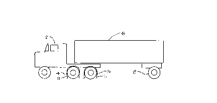
Figure 1 is a side elevation of a typical vehicle
for which an embodiment of the invention would be used;
Figure 2 is a side view of a large wheel mounted
tire and the embodiment of the invention mounted for use
upon a large wheel mounted tire; and
Figure 3 is a perspective view of a specific
embodiment of the invention.
Detailed Description of Specific
Embodiments of the Invention
Referring to the drawings, Figure 1 represents a
side elevation of a typical cargo hauling vehicle with a
.,
, .

-. 2 0 3 3 2 1 ff
_ - 3 -
tractor 2 having front drive wheels 4 and rear drive wheels
5 and a trailer 6 with a set of rolling wheels 8 shown at
the right. In heavy snow conditions or where road condi-
tions are slippery, it is customary to secure a set of
chains around the respective drive wheels 4 and 5, in order
to provide better traction. These chains are readily
available in the marketplace. Typically, the chains are
draped over the drive wheels from the top, with the ends
thereof at the bottoms of the drive wheels. The ends are
then secured together at the outside and inside of each
wheel, or wheel set, by chain end linking devices. This
requires the driver to get down on his or her hands and
knees, or even lie down in the snow or mud, in order to
reach to the insides of the drive wheels to secure the end-
to-end chain linkages. In some cases, the driver's legs
will stick out onto the highway, which is dangerous for the
driver, when there is traffic on the highway.
As can be seen in Figure 2, the clip 10 is
mounted transversely and frictionally about the wheel-
mounted tire 12 grasping the sidewall section of said tire
12.
Figure 2 also illustrates the chain 11 which is
draped around the circumference of the tire 12, and the
manner in which the chain holding clip 10 holds one end of
the chain 11 against the tire 12. The depiction illus-
trated in Figure 2 represents the situation after the
driver has draped the chain 11 around the circumference of
the tire 12, with each end of the chain 11 basically at the
bottom area of the tire. The clip 10 is then secured over
the forward end of the chain 11, and the vehicle is driven
forward so that the tire and chain rotate about 120.
Normally, the driver would drive the vehicle forward so
that the wheels 4 and 5 rotate about 160 to 200. This
position places the chain ends more or less at the top of
the tire for easy accessibility. In this position, the

~, 2 0 3 3 2 1 ô
-- 4
clip 10 holds the end of the chain 11 against the tire 12.
Normally, the chain 11 would fall away from the tire onto
the ground. It is an easy task for the driver to secure
the ends of the chain together, without having to kneel or
lie in the mud or snow. The exposure of the driver to
hazardous oncoming traffic is also minimized.
Figure 3 illustrates an isometric view of the
chain holding clip 10. As indicated in Figure 3, the clip
10 has a general U-shape comprising a longitudinal base 14
joining a pair of vertically extending side arms 16 and 18
respectively. The arms 16 and 18 have respectively in the
areas proximate to the ends thereof, a pair of inwardly
projecting curvatures 20 and 22. These curved areas 20 and
22 are designed to grip the sidewalls of the tire 12.
Since the distance between the side arms 16 and 18 proxi-
mate to the base 14 are wider than at the curved areas,
these wider areas are adapted to enable the chain or chains
to fit therein. The clip 10 depicted in Figure 3 can be
shaped so that it will fit over single or dual tires, as
required. Once the ends of the chain(s) are secured
together, then the clip 10 is removed and the driver can
drive the vehicle away with the chain(s) secured in place.
An advantage of the clip 10 is that it enables the end of
the chain to be held taut, thereby making it easy for the
driver to secure the two ends of the chain snugly together.
Although only a single embodiment of the present
invention has been described and illustrated, the present
invention is not limited to the features of this embodi-
ment, but includes all variations and modifications within
the scope of the claims.

Dessin représentatif
Une figure unique qui représente un dessin illustrant l'invention.
États administratifs

2024-08-01 : Dans le cadre de la transition vers les Brevets de nouvelle génération (BNG), la base de données sur les brevets canadiens (BDBC) contient désormais un Historique d'événement plus détaillé, qui reproduit le Journal des événements de notre nouvelle solution interne.

Veuillez noter que les événements débutant par « Inactive : » se réfèrent à des événements qui ne sont plus utilisés dans notre nouvelle solution interne.

Pour une meilleure compréhension de l'état de la demande ou brevet qui figure sur cette page, la rubrique Mise en garde , et les descriptions de Brevet , Historique d'événement , Taxes périodiques et Historique des paiements devraient être consultées.

Historique d'événement

Description Date
Le délai pour l'annulation est expiré 2001-12-27
Lettre envoyée 2000-12-27
Inactive : Taxe finale reçue 1997-09-05
Accordé par délivrance 1997-08-12
Inactive : CIB attribuée 1997-07-21
Inactive : CIB en 1re position 1997-07-21
Inactive : CIB enlevée 1997-07-21
Inactive : Dem. traitée sur TS dès date d'ent. journal 1997-06-10
Inactive : Renseign. sur l'état - Complets dès date d'ent. journ. 1997-06-10
Préoctroi 1997-04-11
Un avis d'acceptation est envoyé 1997-01-21
Demande publiée (accessible au public) 1992-06-28
Toutes les exigences pour l'examen - jugée conforme 1992-06-05
Exigences pour une requête d'examen - jugée conforme 1992-06-05

Historique d'abandonnement

Il n'y a pas d'historique d'abandonnement

Historique des taxes

Type de taxes Anniversaire Échéance Date payée
Taxe finale - petite 1997-04-11
TM (brevet, 7e anniv.) - petite 1997-12-29 1997-12-29
TM (brevet, 8e anniv.) - petite 1998-12-29 1998-12-07
TM (brevet, 9e anniv.) - petite 1999-12-27 1999-11-22
Titulaires au dossier

Les titulaires actuels et antérieures au dossier sont affichés en ordre alphabétique.

Titulaires actuels au dossier
JOSEPH DESCHENES
Titulaires antérieures au dossier
S.O.
Les propriétaires antérieurs qui ne figurent pas dans la liste des « Propriétaires au dossier » apparaîtront dans d'autres documents au dossier.
Documents

Pour visionner les fichiers sélectionnés, entrer le code reCAPTCHA :


Pour visualiser une image, cliquer sur un lien dans la colonne description du document. Pour télécharger l'image (les images), cliquer l'une ou plusieurs cases à cocher dans la première colonne et ensuite cliquer sur le bouton "Télécharger sélection en format PDF (archive Zip)" ou le bouton "Télécharger sélection (en un fichier PDF fusionné)".

Liste des documents de brevet publiés et non publiés sur la BDBC .

Si vous avez des difficultés à accéder au contenu, veuillez communiquer avec le Centre de services à la clientèle au 1-866-997-1936, ou envoyer un courriel au Centre de service à la clientèle de l'OPIC.


Description du
Document 
Date
(aaaa-mm-jj) 
Nombre de pages   Taille de l'image (Ko) 
Page couverture 1997-08-18 1 40
Abrégé 1993-11-06 1 21
Page couverture 1993-11-06 1 12
Description 1993-11-06 4 159
Dessins 1993-11-06 1 14
Revendications 1993-11-06 1 24
Abrégé 1997-01-21 1 22
Description 1997-01-21 4 170
Dessins 1997-01-21 1 16
Revendications 1997-01-21 4 141
Dessin représentatif 1997-08-18 1 3
Avis concernant la taxe de maintien 2001-01-24 1 176
Taxes 1999-11-22 1 109
Taxes 1998-12-07 1 92
Taxes 1997-12-29 1 137
Correspondance 1997-09-05 1 28
Taxes 1996-12-09 1 46
Taxes 1995-12-13 1 43
Taxes 1994-11-25 1 46
Taxes 1993-12-13 1 37
Taxes 1992-12-22 1 36
Correspondance de la poursuite 1991-08-16 7 209
Correspondance de la poursuite 1991-08-16 13 537
Courtoisie - Lettre du bureau 1992-08-27 1 45
Correspondance reliée aux formalités 1990-11-07 2 35
Correspondance reliée aux formalités 1997-04-11 2 73
Courtoisie - Lettre du bureau 1990-12-10 1 21
Courtoisie - Lettre du bureau 1992-07-02 1 41
Courtoisie - Lettre du bureau 1990-02-10 1 41
Correspondance de la poursuite 1992-06-05 1 27
Correspondance de la poursuite 1996-10-25 8 360
Correspondance de la poursuite 1992-10-06 1 28
Demande de l'examinateur 1996-08-02 2 77
Correspondance de la poursuite 1994-08-16 4 121
Demande de l'examinateur 1994-05-05 1 53