Note : Les descriptions sont présentées dans la langue officielle dans laquelle elles ont été soumises.
3~
- 1 - 5~;, 507
~ETHOD~3 ~ID APPARa~!US FO}~ ACCURATELY A8~EIIBI-ING
~ lGl: 8CALE ~AC~IINB PAP~T8
BAC}~GROUND OF T~l2_INVE:NTION
Field of the Invention
The present invention is directed to methods and
apparatus for assembling large scale machine parts.
Specifically, methods and apparatus are provlded for
liftiny and torquing steam turbins throttle valve bushings
in a controlled manner.
Although large scale machinery such as steam
turbines are comprised of smaller sub-assemblies and parts
which are assembled using conventional fasteners such as
threaded connections, the size and bulk of these parts
makes assembly an extremely difficult task. For example, a
steam turbine throttle valve bushing which is threaded into
a throttle valve bonnet weighs about 120 pounds (54 kg).
The bushing has a 5.50-12 UN ~hread, with three close
fitting lands below the thread. To assemble the bushing
into the bonnet, it must be carefully lowered, the threads
aligned, and tightened to an appropriate torque.
Unfortunately, this type of delicate assembly
operation is not easily performed by the cranes and other
apparatus which are typically used to manipulate such
parts. As the bushing is heing lower~d, it will contact
th~ threaded portion of the bonnet. At this point it is
difficult to control most ma~erial handling equipment with
sufficient precision to prevent the ~ull welght o~ the
bushing from bearlng on the bonnet thr~ads. This is not a
desirablP situation, ~or several reasons. First, the parts
- 2 - 55,so7
may contact one another in a manner which leads to damage
of the threads. The parts may also be brought together in
a manner which leads to cross-threading, particularly if
the threaded portions are no~ clearly visible and the size
o~ the part makes i~ difficult to ~eel" i~ cross-threading
has been initiated. Also, even if the parts are initially
assembled in a proper alignment, the friction created by
the weight of the parts may lead to binding or other
difficulties which make accurate torque measurements
difficult.
Therefore, it would be desirable to be ahle to
provide a resilient connection between materials handling
equipment and the part being handled. It would be further
desirable to provide methods and apparatus whereby parts
may be guided to a location in a controlled manner,
avoiding the problems created by impact and imprecise
handling, while allowing subsequent final assembly to a
specified torque in an efficient manner.
~UMNARY QF T~ INV~NTION
Accoxdingly, it has now been found that large
scale parts may be more readily assembled using apparatus
for lifting and applying torque to an object comprising a
hoist ring for connecting the apparatus to a lifting
apparatus and a housing affixed to the hoist ring. A drive
means ~or attaching a means for applying a torque is
relsasably connected to the hou~ing by a socket retainer.
The housing comprises a counterbalance for resiliently
connecting the socket retain~r and the housing. The
apparatus also comprises a means for supporting the object
being a~sembled. A body portion connects the drive means
and the support, the body portion is adapted to engage a
portion of the object in order to apply a torque to the
ob~ect during assembly. Th~ counterbalance reduces the
force due to the weight of the object when the object is
lifted to the posi~ion from which it will be torqued, and
the torque applied to the drive means i8 trang~erred
through the body portion to the ob~ect. Thus, the problems
~u;~3~ f~
3 - 55,507
~ssociated with the handling of large parts are
substantially reduced, now that the initial threading takes
place under conditions of reduced force~ The apparatus of
'he present invention creates a "soft" or "floatiny"
connection between the ma~erial handling apparatus and the
part being assemkled. In a preferred embodiment, the
resilient means are springs which are placed in
compression. The apparatus also pre~erable comprises a
releasable connection ~etween the counterbalance and the
body portion. By releasing this connection, the full
weight of the part is allowed to bear on the other part.
After releasing the resilient connection, the body portion
remains, exposing a portion which is adapted to receive a
torque wrench or other assembly tool.
In a preferred embodiment, apparatus for
installing a throttle valve bushing in a throttle valve
bonnet is disclosed. The assembly apparatus comprises a
body portion having a first end and a second end, the first
end ~orming a socket for manipulating a fastener, the
second end is adapted to receive a means for applying
torque to the apparatus. A rod portion having threads on
at least a portion thereof is releasably attached to the
first end of the body portion and a support means for
supporting the throttle valve bushing is af f ixed to the
distal end of the rod.
The spring countexbalance ~or reducing the force
between the throttle valve bushing and the throttle valve
bonnet, preferably comprises a housing portion having a
first end and a second end, the first end has a hoist ring
means for cooperating with a lifting device, and the second
end is releasably connected to the second end of the body
portion. A resilient means is disposed between the first
and second end of the housing which permits elastic
displacement of the f irst end relative to the second end.
Thus, the normal force due to the weight of the bushing is
reduced by the ~orce created by the displacement of the
resilient means.
3~
- 4 - 55,507
Methods o~ assembling machln~ parts are also
disclosed. A first and a second part having threaded
connections, the ~irst part to be assembled to the second
and having a means for applying a torque, are provided.
Initially, an assembly apparatus having a ~irst end adapted
to cooperate with the means for applying a torque to the
first part; a second end adapted to be connected to
material handling apparatus is affixed to the first part.
The assembly apparatus provides a releasable resilient
connection between the material handling apparatus and the
first part. The assembly apparatus is then connected to
material handling apparatus and the first part is moved
into a position to be assembled to the second part. The
first part is then lowered into assembly position and the
threaded portions of the parts are initially engaged. The
first part is, however, resiliently supported by the
assembly apparatus such that its full weight does not bear
upon the second part. The releasable resilient connection
between the material handling apparatus and the first part
is then removed. Torque may then be applied to the second
end of the assembly apparatus and the assembly apparatus
removed from the first part, completing the assembly
process.
BRI~F DB8CRIPTION OF ~B D~AWIN~
The invention may be better understood, and
~urther advantages and uses thereof are readily apparent,
when considered in view of the following detailed
description of exemplary embodiments, taken with the
accompanying drawing in which:
FIG. 1 is an overall side view of a preferred
embodiment of a lifting and torquing apparatus of the
present invention.
FIG. 2 is a partial side sectional view of the
apparatus o~ FIG. 1 illustrating the details of a preferred
spring counterbalance.
- 5 - 5~,507
~C~IPTION OF ~RB pRpF~RRED-~M~o~IMENrr~
The lifting and torquing device disclosed by the
present invention permits a large and unwieldy part to be
liftsd by a crane or hoist and accurately guided into the
location into which it is to be assembled or installed.
Referring now to FIG. 1, an overall side view of the
present invention is shown. At a first end of the body
portion 104 of the apparatus o~ the present invention 100 a
safety hoist ring 102 is provided. The hoisk ring 102
permits lifting and manipulating the apparatus of the
present invention 100 and the part 200 which is attached to
it by a crane, or other means for lifting which provid~s a
force, as shown by the arrow in FI~. 1. The hoist ring 102
may be used alone or in combination with further li~ting
points 210 disposed on the object or part 200 being
a~sembled. ~s shown, in the case of an unwieldy or
otherwise large part 200, it will be desirable to include
one or more further points of attachment 210. The further
points of attachment 210 may be connectPd to the same
lifting apparatus as the safety hoist ring 102, or to other
lifting apparatus. Alternatively, cables or other guidin~
means may be connected to the further points of attachment
210 and used to guide, adjust or otherwise manipulate the
object while it is being lifted.
The hoist ring 102 is affixed to the spring
counterbalance assembly 110, explained in detail below.
The spring counterbalance assembly 110 provides a resilient
or "so~t" connection between the crane or hoist and the
par~ 200. Thus, in the ~roadest sense, the present
invention permit~ a resilient connection between a means
for lifting an object, such as a crane, and the object 200
being lifted. Among the advantages o~ the apparatus
disclosed is that the present invention permits the
installation of a part 200 and its subsequent torquing into
final a~sembly in a convenient and efficient manner.
As shown in FIG. 1, the spring counterbalance 110
is releasably connected to the body portion 104 o~ the
_ ~ _ 55,507
apparatus by a releasable connecting means 116.
Preferably, the releasable connecting means is provided by
a single acting ball lock pin 106 which is inserted in a
bore which passes through both the spring counterbalance
llO and the body portion 104. A through hole 105 is also
preferably provided. This permits a bar to be inserted
through the body 104, allowing the assembly to be
manipulated. Upon removal of the lock pin 106, tha spring
counterbalance llo can be removed from the rest o* the body
portion 104 and the remaining apparatus is manipulated
using a bar inserted in the through hole 105. Also, upon
removal of the spring counterbalance llO a means for
applying torque 117 to the body portion 104 is exposed,
thereby enablinq the part to be torqued into final
assembly.
At the end of the body portion 104 opposite the
spring counterbalance 110 a socket means 108 for engaging a
connection on the object being assembled is provided. For
example, in the case of the steam throttle valve bushing
described above, a 4.75 inch (120 mm) hexagonal connection
is provided to torque the bushing into the throttle valve
bonnet. Thus, in a preferred embodiment, a 4.75 inch (120
mm) socket 108 is affixed to or formed from the distal end
of the body portion 104.
In order to lift an object 200, a connection
between the ob~ect 200 and the socket means 108, must be
provided. Such a connection results in the apparatus of
the present invention 100 and the object 200 being
assembled and acting as a single piece. The object 200 and
apparatu~ 100 are thus capable of being manipulated
together until assembly is complete and the apparatus of
the present invention 100 removed from the object 200. In
a preferred embodiment, a threaded rod 120 connected to the
body portion 104 and socket 108 is provided. The proximal
end of the threaded rod 120 is preferably rigidly but
relea~ably connected to the body portion 104. This is
preferably provided by a hole or other means o~ engagement
q~
- 7 - 55,507
in the socket 108 and a set screw 109 which is
perpendicular to th~ threaded rod 120 and prevents it ~rom
being withdrawn from the socket 108. At the distal end of
the threaded rod 120 a guide or support means 122 is
provided. As shown, the support means is preferably
threaded directly onto the threaded rod 120. A knurled
section 123 is pre~erably provide~ to permit the support
means to be tight~ned against the object 200. Thus, as
shown in FIG. 1 the threaded rod 120 extends through the
object 200 and is terminated at its distal end by the
support means 122. The support means 122 is threaded and
tightened against the object 200 to firmly hold the
apparatus of the present invention 100 against the object
200. It will be understood that the design of the support
means 122 will be dete~nined by the geometry of the object
200. As depicted in FIG. 1, if the portion of the object
through which the threaded rod 120 extends is a bore of
relatively small diameter, the support means 122 may be
comprised of a slightly larger member having a surface
which urges against the object 200. To manipulate other
objects, it may be desirable to provide a support 122 of
greater surface area. In all events, the support means 122
should be designed so that it may be removed from the body
portion 104, allowing the apparatus of the present
invention 100 to be removed from the object or part 200
being assembled.
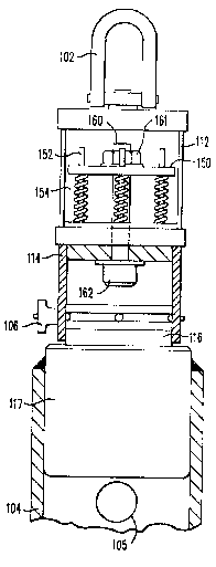
The details of a preferred embodimenk of the
spring counterbalance 110 of the present invention are
shown in FIG. 2. The hoist ring 102 is affixed to a ~irst
end of the counterbalance housing 112. The opposite end of
the counterbalance housing 112 is attached to socket
retainer means 114. The socket retainer means, 114,
provides the connection between the counterbalance housing
and the body portion 104 o2 the apparatus. As explained
above, the socket retainer means 114 is preferably
conn~cted to the body portion 104 in a releasable fashion.
A pin 106 is pre~erably provided for this purpose. The pin
~ ~ ~ 55,507
106 passes through both the socket retainer means and a
drive means 116, for applying torque to the body portion
104. In a preferred embodiment, the drive means 116
comprises a one inch (25 mm) square drive. Preferably, the
drive means 116 is the drive end of a 2.25 inch t57 mm)
socket 117. The outside diameter o~ the socket 117 is
about 3.25 inches (82 mm) and can thus be fitted into a
section of tubing having approximately a 3.25 inch (82 mm)
inner diameter and welded in place. A socket 108 can be
lo similarly welded in place at the opposite en~. Thus, in a
preferred embodiment, a shown in FIG. 1, the body portion
104 is thus comprised of a ~ubulax section having a square
drive socket 117 welded to a first end such that the drive
portion 116 is exposed and another socket 108 welded to a
second end such that the socket portion is exposed.
Referring again to FIG. 2, inside the
counterbalance housing 112, the resilient mean~ which
provides the "~loating" effect of the lifting aspect of the
present invention is shown. Preferably a compression plate
150 is provided which is slide fitted to the interior
portion of the counterbalance housing 112. The compression
plate 150 is shaped to slide fit over and to avoid
interference with the connecting bolt 160. ~s shown, the
head 162 of ~he connecting bolt 160 is lodged against the
inner surface of the socXet retainer means 114. The
threaded portion of the connecting bolt 160 extends
upwardly into the counterbalance housing 112. The distal
end o~ the connecting bolt 160 is fitted with a nut 161 or
other threaded connector having a somewhat larger diameter
than the outside diameter of the bolt 160. As shown, a
washer may also be placed between the nut 161 and the
compression plate 150. The diameter of the opening in the
compression plate 150 must therefore be slightly larger
than the outside diameter of the bolt 160 but somewhat
smaller than th diameter of the nut 161 in order to permit
the plate 150 to urge against the nut 161 without slipping
off.
_ ~ _ 55,507
Affixed to the counterbalance housiny 112 are one
or more ~uide posts 152 which ex~end through openings in
the compression plate 150. The openings are sized to
provide a sliding fit between the compression pl~te 150 and
the posts 152. Disposed between the compression plate 150
and the bottom of the counterbalance housing 112 and
surrounding ~he guide posts 152 are compression springs
154. In FIG. 2, one compression spring 154 is illustrated,
while two others are shown schematically. The number and
position of the springs 154 depends upon a variety of
factors, such as the load being carried and the spring
constant of available springs. Moreover, although a
compression spring assembly as shown is a preferred
embodiment of the present invention, it may be desirable to
provide other resilient means, such as tension springs,
elastomeric members or hydraulic cylinders. In most
applications, the apparatus will be designed such that the
load placed upon the apparatus displaces the socket
retainer means 114 from the spring counter balance 110 by a
small amount. This displacement permits the apparatus and
the attached part to resiliently travel in either direction
as it is handled and brought into place.
In use, the apparatus of the present invention is
first attached to the part to be assem~led. This is
preferably accomplished by placing the socket 108 over the
portion of the part adapted to receive it and threading the
support 122 onto the threaded rod 120. In other
embodiments, other means for attachment may be necessary
if, for example, an appropriate bore through which the
threaded rcd 120 may be passed does not exist. In this
situation, the design of the apparat~s would be modified by
adding appropriate straps, braces, extensions or other
releasable means of attachment to the part. After the
apparatus has been installed on the part, assembly using
conventional materials handling equipment may begin.
The provision o~ a sa~ety holst ring 102 on the
apparatus permits at least one point of attachment to a
3~:3~
- 10 - 55,507
crane or other lifting device. It may be desirable in some
circumstances to provide other points of attachment to the
object being manipulated in order to permit stable
handling. The part is then moved to the approximate
location of assembly. Substantially all of the weight of
the part is preferably borne by the safety hoist ring 102,
and thus by the apparatus of the present invention. As
explained above, at this point, the socket retainer means
114 will be displaced from the spring counter balance 110.
The lowering of the part to be assembled may now begin.
As the part is lowered by the action of the
crane, the threads and/or other portions of the part and
the location to which it is being assembled will come into
contact. However, unli]ce conventional apparatus, the
contact force will not be due to the full weight of the
part. Instead, the apparatus of the present invention
provides a counterbalancing force, by action of the spring
counterbalance llO described above, which creates a "soft"
assembly. As the part is lowered and initial contact is
made, the part may be more precisely manipulated during
initial engagement of the threads by the resiliency
provided by the apparatus of the present invention. As
shown, a bore 105 is provided through the body portion 104
which permits a bar to be inserted through the apparatus.
The bar may be used to ease the threads into place and
initially turn the parts together, with the likelihood of
cross threading almost eliminated.
After the part has been initially threaded into
place, the material handling apparatus is either
disconnected or the tension slackened such that no upward
force is exerted upon the apparatus. The pin 106 may then
be pulled and the spring counterbalance 110 removed. The
drive means 116 is thereby exposed. At this point, since
the part is properly threaded in place, an appropriate
torque wrench may be applied to the drive means. The part
can now be assembled to its final torque.
~ 5,507
After the part is fully in place, the apparatus
of the present invention may be removed either by
unthreading the support 122 and withdrawing the apparatus
with the threaded rod 120 attached, or by removing the
threaded rod 120 ~y releasing the set screw 109 which
retains it in place. The latter operation may be conducted
from the samP side as the torquing operation and may be
preferable in certain si~uations where access is limited.
In the case of alternate methods of attaching the apparatus
to the part, alternate removal methods must also be
proYided, as will be understood by those of ordinary skill.
Although certain embodiments of the present
invention have been described with particularity, numerous
variations and modifications will readily present
themsslves to those of ordinary skill. Accordingly,
reference should be made to the appended claims in order to
determine the scope of the present invention.