Note : Les descriptions sont présentées dans la langue officielle dans laquelle elles ont été soumises.
BACKGROUND OF INVENTION
Field of the ~nvention
The present invention relates to an
automatic spraying device Eor farm animals and
wherein the anlmaLs are sprayed automatically when
passing through a defined passageway~
Descrlption of Prior Art
Various devices are known to spray animals
with a disinfectant or insecticide liquid so as to
kill various types of flies that lodge themselves in
the hair or skin of the animals. However, many of
-these treatments are not totally effective for the
reason that they do not provide complete spraying of
the animals and often these treatments are given in
feed areas where the insecticide will also be sprayed
within the feedstock of the animal. Thus, some of
these chemicals can find -their way, for example, in
the milk of cows and the milk has to be discarded.
Also, most spraying devices are construc-ted for
occasional use only when livestock is found to
contain infectuous flies.
Experiments have also proven that if cows
are bothered by flies during grazing, the flies will
affect the rate at which they graze and the cows will
produce 5 to 20~ less milk than if they are not
bothered by flies. The spraying of farm animals with
hand-held devices has also proven to be time-
consuming and often the livestock is not sprayed
uniformly. Various animal-opera-ted sprayers have
been devised in an attempt to solve these problems
and such are~, for example, described in U.S. Patents
3,884,192; 3,183,890; 4j580,529 and 4,478,176. All
of these Patents describe devices with various
mechanisms that trigger automatic spraying of
~1
,. , ~ ~ ,.
,
2~3~ 2
animals. The present invention relates to such
devices and attempts to solve their various
deficiencies.
SUMMARY OF INVENTION
It is, therefore, an object of the present
invention to provide an automatic spraying clevice for
farm animaLs which substantiaLly overcomes all oE the
above-mentioned disadvantages oE the prior art.
Another feature of the present invention is
to provide an automatic spraying device for farm
animals and wherein the device is fully automatic and
controlled by electronic control circuits to operate
valves and a pump automatically and which requires
very little servicing~
Another feature of the present invention is
to provide an automatic spraying device for farm
animals wherein the animals are sprayed on a
continuous basis when the animals enter or leave
predetermined areas which are remote from feed areas.
According to the above objects, from a
broad aspect, the present invention provides an
automatic spraying device for farm animals. The
device comprises a framework defining a passage
through which farm animals are directed one-by-one.
Electronic detection means is associated with the
passage and connected to electronic control circuit
means to provide a detection signal thereto when a
farm animal enters the passage. Spray nozzles are
oriented with respect to the passage to spray animals
passing through the~passage. Pump means is provided
to supply a chemically treated liquid to the spray
nozzles under pressure. The pump means is actuated
; by the control circuit upon reception of the
detection signal. Valve means is provided to connect
the pump to the spray nozzles. A chemically treated
liquid reservoir is connected to the pump means. An
~:
- 2 -
, . ,: ` . . . : .
. . . . - , . ~ : -
., '. ~ ' :
, ~ - . ' . ' .
-
:
.. ...
au-tomatic pump deactuation means, including timing
means, is also provided to deactuate the pump means
after a predetermined tlme lapse after reception of a
valve closing si~nal where -the valve means is closed
to shut off the spray nozzles.
BRIEF DESCRIPTION OF DRAWINGS
~ preferred embodiment of the present
invention will now be described with reference to the
accompanying drawings in which:
FIGURE 1 is a perspective view showing the
construction of a framework defining a passage in
which -the farm animals are sprayed;
FIGURES 2A and 2B are schematic diagrams
illustrating the construction of the electronically
controlled circuit; and
FIGURE 3 is a schematic diagram showing the
interconnection of the detecting devices as well as
the pump and the contro] valves.
DESCRIPTION OF PREFERRED EMBODIMENTS
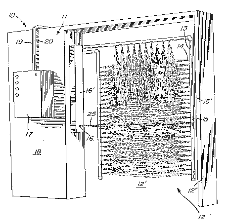
Referring now to the drawings, and more
particularly to Figure 1, there is shown generally at
10, the automatic spraying device of the present
invention. The device comprises a framework 11 which
defines therein a passageway 12 through which farm
animals are directed, one-by-one, such as when they
leave the stables for outside grazing or else when
they enter a stable area. It is well known that cows
will follow one another instinctively when leaving or
returning to their stable. The equipment is located
away from feedstock so that the chemically treated
liquid which is sprayed on the animals does not mix
with the feedstock. By spraying the animals~with an
insecticide liquid, the animals are not disturbed by
flies during grazing and accordingly will take in
more feed and thus provide more mllk.
: :
-- 3
.
~3~
The passageway is provided with an inlet
opening 12' and an outlet opening 12" and between
which is defined a passageway in which conduits 13
having spray nozz.l.es 1~ are disposed. These conduits
13 a.re fecl w:ith a chemlca.l.ly t.reated li.quid under
pressure by a pump, as wil:L be described later, which
:is actuated by a detection signal which is generated
by an elec-tronic detection means such as the inrared
transmitter 15 and the infrared receiver 16 mounted
on opposed sides of the inlet opening 12'. These
detectors 15 and 16 can be mounted on the inlet and
outlet openi.ngs 12' and 12" or simply on an inlet
opening, as desired. Accordingly, animals can be
sprayed when leaving and/or entering their stable or
any other designated area. A control panel 17 is
mounted on a wall 18 associated with the framewor~
10. The panel 17 also has a reservoi.r therein which
can be automatically fed a chemica]. i.nsecticide
through a feed line 19 and an admixture of water
through feed line 20. These feed lines are each
connected to pumps (not shown) which are actuated
when the level of liquid in the reservoir goes below
a predetermined level so as -to supply a predetermined
quantity of chemical and water so that the devi.ce can
continuously operate automatically.
Referring now additionally to Figures 2 and
3, there will be described the operation of the
device and the construction of its electronic control
circuit. As shown in Figure 3, the infrared
transmitter 15 is a light emitting diode which is fed
by an infrared emitter circuit 21 in Figure 1. This
emitter utilizes two chronometers 22 to provide a
pilot signal on its output 23 which is connected to
the light emitting diode 16 -to transmit a tonality.
An infrared receiver transistor 16 receives the
infrared signal ~rom the transmltter 15 and provides
- 4 - ~
.
: . . .' : ' :
-, . , . . ',: ~ ' , . '
at its output connection 24 a detection signal when
the light beam 25 (Figure 1) is interrupted by a farm
animal crossing the en-trance opening. Of course, the
transmitter and receiver housings 15' and 16' can be
Located at different heights or levels within the
opening depending on the type of farm animals to be
spra~ed. For example, iE the livestock consists of
pigs, then the detec-tors would be located much lower
in the opening.
The detection signal at the output 24 of
infrared receiver 16 is connected to the input 26 of
an amplifier circuit 27 which generates at i-ts output
28 a valve closing signal. The amplifier circuit 27
conslsts of an inverter transistor 29 connected to an
input gate of an integrated circuit 30, the output 28
of which provides the valve closing signal. The
valve closing signal drives a further integrated
circuit 31 which cons-titutes the pump drive and this
circuit is connected at its ou-tput to a further
integrated circuit 32 which provides the biasing
signal to the current amplifier transistor 33 to bias
the diode 34 conductive and provide the energizing
current to the relay coil 35 thereby energizing the
coil to cause a switching action of the switch 36 to
in turn provide a supply to the pump 37 (Figure 3).
A fuse 38 protects the pump from voltage surges.
The valve closing signal 28 at the output
of the integrated circuit 30 is also connected to a
valve closing circuit 40 and more particularly to the
base of a further D.C. current amplifier transistor
41 whereby to provide the supply to the coil 43 of a
further relay 44. This contact provides the supply
across the coils 45 of the two valves 46 which are
connected to the piping 13 to open the conduits
be~ween the pump and the piplng wler^by to supply
- 5 -
~, ~3 ~
chemically treated liquid therein under pressure to
spray the animal which has just interrupted the
in~rared beam.
The ON/OFF switch 47 is connec-ted in the
supply :l.i.ne to the val.ves to interrupt the pump
shou:Ld :it be necessary to shut of:E the dev.ice. The
supp:Ly is provided by the supply circuit 48 to
generate a 5-volt regulated, one-amp supply to the
circuit components. A light emit-ting diode 49
indicates if t.he supply is on or off. A sensor 50 is
associated with the liquid reservoir and provides a
ohmic signal to indicate the level of the liquid in
the liquid reservoir. This signal is connected to
the input 51 of an amplifier 52 forming part of a
liquid level detector circuit 53. This amplifier 52
biases the transist.or 54 conduc-tive upon reaching a
predetermined value which in turn connects the 4.8
volts to the anode of the light emitting diode 55.
This provides an indication that the l.eve:L is low and
that more liquid is to be supplied to the reservoir.
This supply can be done automatically, as previously
described, by connecting this alarm signal to proper
actuation circuitry (not shown) or else the supply
can be done manually by an operator but only when the
signal light is on.
The circuit 56 constitutes a reset circuit
which maintains the circuit components in their
stahle logic state. An important circuit in the
system is the time delay circuit 57 which includes a
charging capacitor 58 which is connected to the
output 59 of the integrated circuit 31 to which is
fed the valve closing signal from the output 28 of
the amplifier 30. This capacitor 58 is connected in
series with a discharging diode 59 to discharge the
capacitor rapidly after a predetermined charge and
this provides Eor a time delay of appro~imately two
.
' '' ~: : ' ' .
" ' ' ' ' -' ' '-. :' '' '
', . " " '. " " ~' ~ ' ~ ,
,'.', . ::' ', , .,,,. ,', , ''',~.': ,.. '''.',' ' ' .
minutes after the capacitor starts charging. This
state occurs immediately after the infrared beam
reappears after being obstructed thereby providing a
valve closing signal or a valve closing state at the
output 23 of the ampliEier 30. After this predeter-
minecl chaxging time, the capacitor discharges and
thereby renders the trans:istor amp:lifier 33
non-conduct:ive thereby causing the relay 35 to
deenergize to cut the supply to the pump.
Accordingly, the equipment shuts off au-tomatically.
The nozzles are only operated when the valves are
open and these valves immediately close upon the
reappearance of the infrared beam.
The following description is a definition
of the components as appearing in the schematic
diagrams of Figures 2 and 3 and may help in providing
a better understanding of the construction and
operation of these circuits. Resistors Rl, R2 and R3
are voltage dividers to provide proper reference
voltages of 1.2 volts and 3.8 volts. Resistor R4
acts as a pull-up resis-tor on the collector of
transistor Ql. Resistor RS is a current limiting
resistor for diode Dll. Resistor R6 is also a
current limiting resistor for the base of ~2.
Resistor R7 is a pull-up resistor for the operational
amplifier 32 and connected to pin 1 of the integrated
circuit. Resistor R8 is a charging resistor for the
capacitor C10. Resistor R9 is a current limiting
resistor for the base of transistor 29~ Resistor R10
is a pull-up resistor for the operational amplifier
30 and is connected to the pin 2 of that amplifier.
Resistor Rll is pull-up resistor for the integrated
circuit Q4 and connected to pins 5 and 10. Resistors
R12 and R13 are charging resistors for capacitor C7.
Resistor R14 is a pull-up resistor for the opera-
tional amplifier 52 and connec-ted ~to pln 8 thereof.
:
- 7 -
.
' ' ' :`` :" '.', '' ``. `':' '. ' ' '
,, . . ~ ,
' : ' . .,"' , . . ~ , ` ' . : '
.
This resistor also serves to provide the proper
sensitivity to the liquid level de-tector. Resistor
R15 is a charging resistor for the time delay
capacitor 58. Resistor R16 is a charging resistor
for capacitor C~ Resistor R17 is a pull--up resistor
Eor the operational ampl;ifier 52 and connected to pin
14 thereof. Resistor R18 is a charging resistor for
capaci-tor C5. Resistor RL9 is a current limiting
resistor for the light ernitting transmitter diode 15.
Resistor R20 is a variable resistance for the
discharge of capacitor C5. Resistor R21 is a current
limiting resistor for the base of transistor 33.
Resistor R22 is a pull-up resistor for the opera-
tional amplifier 31 and connected to pin 2 theréof.
Resistor R23 is the input resistor for the opera-
tional amplifier 30 and connected to pin 5 thereof.
Resistor R24 is the feedback resistor and also
connected to the same pin of the amplifier 30.
The diode D1 is utilized to rapidly
discharge the capacitor C10. Diodes D2, D3, D4 and
D5 are voltage rectiEication diodes for -the D.C.
supply. Diode D6 is provided to eliminate negative
supply transients provided by relay 44 when
deactivated. Diode D7 filters the signal for the
D.C. level. Diode D8 is a rapid discharge diode for
capacitor C3 which is the charging capacitor 58 for
the delay circuit. Diode D9 is also utilized for the
rapi~ discharge of the capacitor 58 in accordance
with the level at the output 59 of the amplifier 31.
Diode D10 eliminates the negative supply transients
which are generated when relay 35 is deactivated.
Light emitting diode D13 emits a yellow light -to
indicate a standby condition. Diode D14 is provided
as an isolation element. Capacitors Cl and C2
eliminate high frequency transients in the circuit.
Capacitor C4 is utilized for regulation and for
-
.
-- 8 --
, ~ . , . :.............................. . .
: : . , . .,''' .. ,,............................ - .
.
. ' :' -. ' ' : -:' . - ~
:, , '
.
filtration of the D.C. supply. Capacitor C5 is
utilizecl for the 40 Her-tz supply. Capacitor C6 also
eliminates high frequency transients. Capacitor C7
is ~Itilized Eor the 1,000 Hertz frequency. Capacltor
C8 also eLiminates high frequellcy transients while
capacitor C~ is utilized to provide a time base oE
0.55 seconds. Capacitor C10 i9 utilized for a time
base of appro~imately 1.5 seconds. Capacitor Cll
eliminates -the transients at high frequency for the
integrated circui-t. Capaci-tor C12 is utilized as a
positive feedback capacitor. Capacitors C13 and C14
also eliminate the high frequency transients for the
inteyrated circuit. Capacitor C15 is utilized to
filter the D.C. level before regulation.
The pin connector 60 has ten pins providing
a quick connection and disconnection of the printed
circuit board to which the various componen-ts of the
control circuits are connected. The transformer 61
is a voltage reduction transformer for the 120-volt
A.C. supply connected thereto by the closing of the
ON/OFF switch 47 and provides a 16-volt A.C. output.
The voltage regulator 62 provides the S-vol-t
regulated D.C. supply.
It is within the ambit of the present
invention to cover any obvious modifications of the
preferred embodiment described herein provided such
modifications fall within the scope of the appended
claims.
~` .
.
:: :
.
', ' , '
,: , ' ,:, ;.
:, ':
" ~ . ' .. -