Sélection de la langue

Search

Sommaire du brevet 2034277 

Énoncé de désistement de responsabilité concernant l'information provenant de tiers

Une partie des informations de ce site Web a été fournie par des sources externes. Le gouvernement du Canada n'assume aucune responsabilité concernant la précision, l'actualité ou la fiabilité des informations fournies par les sources externes. Les utilisateurs qui désirent employer cette information devraient consulter directement la source des informations. Le contenu fourni par les sources externes n'est pas assujetti aux exigences sur les langues officielles, la protection des renseignements personnels et l'accessibilité.

Disponibilité de l'Abrégé et des Revendications

L'apparition de différences dans le texte et l'image des Revendications et de l'Abrégé dépend du moment auquel le document est publié. Les textes des Revendications et de l'Abrégé sont affichés :

  • lorsque la demande peut être examinée par le public;
  • lorsque le brevet est émis (délivrance).
(12) Brevet: (11) CA 2034277
(54) Titre français: CAISSON DE REFROIDISSEMENT DESTINE A UN MOTEUR ELECTRIQUE LINEAIRE
(54) Titre anglais: COOLING STRUCTURE FOR LINEAR INDUCTION MOTOR
Statut: Durée expirée - au-delà du délai suivant l'octroi
Données bibliographiques
(51) Classification internationale des brevets (CIB):
  • H02K 1/20 (2006.01)
  • H02K 9/04 (2006.01)
  • H02K 41/025 (2006.01)
(72) Inventeurs :
  • GILMORE, DAVID (Taïwan, Province de Chine)
  • STANNARD, JOHN (Canada)
  • VOLLENWYDER, KURT (Canada)
(73) Titulaires :
  • BOMBARDIER INC.
(71) Demandeurs :
  • BOMBARDIER INC. (Canada)
(74) Agent: MCCARTHY TETRAULT LLP
(74) Co-agent:
(45) Délivré: 1997-03-18
(22) Date de dépôt: 1991-01-16
(41) Mise à la disponibilité du public: 1992-07-17
Requête d'examen: 1991-08-23
Licence disponible: S.O.
Cédé au domaine public: S.O.
(25) Langue des documents déposés: Anglais

Traité de coopération en matière de brevets (PCT): Non

(30) Données de priorité de la demande: S.O.

Abrégés

Abrégé anglais


A primary of a linear induction motor has a plenum
formed on its upper surface to receive cooling air from a
fan. The upper surface of the core is formed with fins to
promote cooling. Air flows from the plenum to side housings
in which the end turns are located. A deflector plate
directs air from the plenum over the end turns of the
windings. Exhaust slots are provided in the housing above
the end turns and a baffle between the housing and the end
turns promotes flow through the end turns as it moves toward
the exhaust slots.

Revendications

Note : Les revendications sont présentées dans la langue officielle dans laquelle elles ont été soumises.


- 6 -
We claim:
1. A primary for a linear induction motor comprising
a core having a plurality of slots in one face thereof, a
housing on each side of said core, motor windings located in
said slots and having end turns extending laterally beyond
said core and into said housing, a plenum chamber on the
opposite side of said core to said one face, a fan to supply
cooling air to the plenum chamber, apertures in longitudinal
surfaces of said plenum adjacent the opposite surface of
said core to permit air to flow out of said plenum and into
said housings, deflector means overlying said apertures to
direct air onto the end turns and outlet means in said
housing to permit egress of air from the housing.
2. A primary according to claim 1 wherein a diffuser
is provided in said plenum to distribute uniformly air from
the fan along the core.
3. A primary according to claim 1 wherein laterally
extending fins are provided on said opposite face.
4. A primary according to claim 3 wherein the outlet
means are located above said end turns.
5. A primary according to claim 3 wherein said core
is formed from laminations and said fins are integrally
formed along one edge of said laminations.
6. A primary according to claim 3 wherein said fins
extend beyond said apertures.
7. A primary according to claim 1 wherein a barrier
extends along said housing adjacent said end turns and said

- 7 -
deflector means extends to the barrier to cause air to flow
between said end turns.
8. A primary according to claim 1 wherein said
deflector means includes an inclined portion extending from
said aperture toward said end turns.
9. A primary according to claim 8 wherein said
deflector portion is located between outriggers extending
laterally from said core to support said housing.
10. A primary according to claim 9 wherein laterally
extending fins are provided on said opposite face of said
core.
11. A primary according to claim 10 wherein said
apertures overlap said fins to permit air flow from said
plenum between said fins.
12. A primary according to claim 11 wherein said
inclined plate extends outwardly and downwardly from above
said apertures.

- 8 -
13. A primary according to claim 8 wherein a
diffuser is provided in said plenum to distribute
uniformly air from the fan along the core.
14. A primary according to claim 8 wherein
laterally extending fins are provided on said opposite
face.
15. A primary according to claim 14 wherein said
core is formed from laminations and said fins are
integrally formed along one edge of said laminations.
16. A primary for a linear induction motor
comprising a core having a plurality of slots in one face
thereof, a housing on each side o said core, motor
windings located in said slots and having end turns
extending laterally beyond said core and into said
housing, a plenum chamber on the opposite side of said
core to said one face, a fan to supply cooling air to the
plenum chamber, apertures in longitudinal surfaces of
said plenum adjacent the opposite surface of said core to
permit air to flow out of said plenum and into said
housings, deflector means overlying said apertures to
direct air onto the end turns and outlet means in said
housing to permit egress of air from the housing, wherein
laterally extending fins are provided on said opposite
face, and wherein the outlet means are located above said
end turns.
17. A primary according to claim 16 wherein a
diffuser is provided in said plenum to distribute
uniformly air from the fan along the core.
18. A primary according to claim 16 wherein said
core is formed from laminations and said fins are
integrally formed along one edge of said laminations.
19. A primary for a linear induction motor
comprising a core having a plurality of slots in one face

- 9 -
thereof, a housing on each side of said core, motor
windings located in said slots and having end turns
extending laterally beyond said core and into said
housing, a plenum chamber on the opposite side of said
core to said one face, a fan to supply cooling air to the
plenum chamber, apertures in longitudinal surfaces of
said plenum adjacent the opposite surface of said core to
permit air to flow out of said plenum and into said
housings, deflector means overlying said apertures to
direct air onto the end turns and outlet means in said
housing to permit egress of air from the housing, wherein
laterally extending fins are provided on said opposite
face, and wherein said fins extend beyond said apertures.
20. A primary according to claim 19 wherein a
diffuser is provided in said plenum to distribute
uniformly air from the fan along the core.
21. A primary according to claim 19 wherein said
core is formed from laminations and said fins are
integrally formed along one edge of said laminations.
22. A primary for a linear induction motor
comprising a core having a plurality of slots in one face
thereof, a housing on each side of said core, motor
windings located in said slots and having end turns
extending laterally beyond said core and into said
housing, a plenum chamber on the opposite side of said
core to said one face, a fan to supply cooling air to the
plenum chamber, apertures in longitudinal surfaces of
said plenum adjacent the opposite surface of said core to
permit air to flow out of said plenum and into said
housings, deflector means overlying said apertures to
direct air onto the end turns and outlet means in said
housing to permit egress of air from the housing, wherein
a barrier extends along said housing adjacent said end
turns and said deflector means extends to the barrier to

- 10 -
cause air to flow between said end turns.
23. A primary according to claim 22 wherein a
diffuser is provided in said plenum to distribute
uniformly air from the fan along the core.
24. A primary according to claim 22 wherein
laterally extending fins are provided on said opposite
face.
25. A primary according to claim 24 wherein said
core is formed from laminations and said fins are
integrally formed along one edge of said laminations.

Description

Note : Les descriptions sont présentées dans la langue officielle dans laquelle elles ont été soumises.

2034277
The present invention relates to linear induction
motors and in particular to a means to improve cooling
thereof.
Linear induction motors are widely used in a
number of industries and present certain advantages over
rotary motors, particularly where propulsion along a
predetermined path or guideway is required. An application
in which linear induction motors have enjoyed commercial
success is the transportation industry where they have been
used to provide the propulsion system for transit vehicles.
The constraints placed on the design of the linear
induction motor in these particular applications have
required that careful attention be paid to cooling of the
motor. This is because the motor has to be located within a
relatively congested area of the vehicle and at the same
time must be appropriately shielded to permit its use in a
public environment.
U.S. Patent 4,642,493 issued November lO, 1987 and
assigned to the assignee of the present application
addresses the issue of providing adequate cooling for the
end turns of the windings of the linear induction motor.
This is provided by locating fans outward of the central
core to force air over the end turns of the motor. This
approach has been successful in improving the performance of
the linear induction motor, although it is desirable to
provide for further extraction of the heat generated during
operation particularly in the central core of the motor.
It is therefore an object of the present invention
to provide an improved cooling system for a linear induction
motor.

-- 2034277
According to the present invention, there is
provided a primary for a linear induction motor
comprising a core having a plurality of slots in one face
thereof, a housing on each side of said core, motor
windings located in said slots and having end turns
extending laterally beyond said core and into said
housing, a plenum chamber on the opposite side of said
core to said one face, a fan to supply cooling air to the
plenum chamber, apertures in longitudinal surfaces of
said plenum adjacent the opposite surface of said core to
permit air to flow out of said plenum and into said
housings, deflector means overlying said apertures to
direct air onto the end turns and outlet means in said
housing to permit egress of air from the housing.
In a preferred embodiment, the fins extend from
the opposite side of the core in a direction parallel to
the slots and are formed as castellations of individual
laminations that constitute the core. In this manner,
increased surface area and adequate ducting of the
cooling air is provided.
Preferably the deflector includes an inclined
portion extending form the aperture toward the end turns.
According to a further aspect of the invention,
there is provided a primary for a linear induction motor
comprising a core having a plurality of slots in one face
thereof, a housing on each side of said core, motor
windings located in said slots and having end turns
extending laterally beyond said core and into said
housing, a plenum chamber on the opposite side of said
core to said one face, a fan to suppIy cooling air to the
plenum chamber, apertures in longitudinal surfaces of
said plenum adjacent the opposite surface of said core to
permit air to flow out of said plenum and into said
housings, deflector means overlying said apertures to
direct air onto the end turns and outlet means in said
housing to permit egress of air form the housing, wherein
laterally extending fins are provided on said opposite

-- 203~277
- 2a -
face, and wherein the outlet means are located above said
end turns.
According to a yet further aspect of the
invention, there is provided a primary for a linear
induction motor comprising a core having a plurality of
slots in one face thereof, a housing on each side of said
core, motor windings located in said slots and having end
turns extending laterally beyond said core and into said
lo housing, a plenum chamber on the opposite side of said
core to said one face, a fan to supply cooling air to the
plenum chamber, apertures in longitudinal surfaces of
said plenum adjacent the opposite surface of said core to
permit air to flow out of said plenum and into said
housings, deflector means overlying said apertures to
direct air onto the end turns and outlet means in said
housing to permit egress of air form the housing, wherein
laterally extending fins are provided on said opposite
face, and wherein said fins extend beyond said apertures.
An embodiment of the invention will now be
described by way of example only with reference to the
accompanying drawings, in which
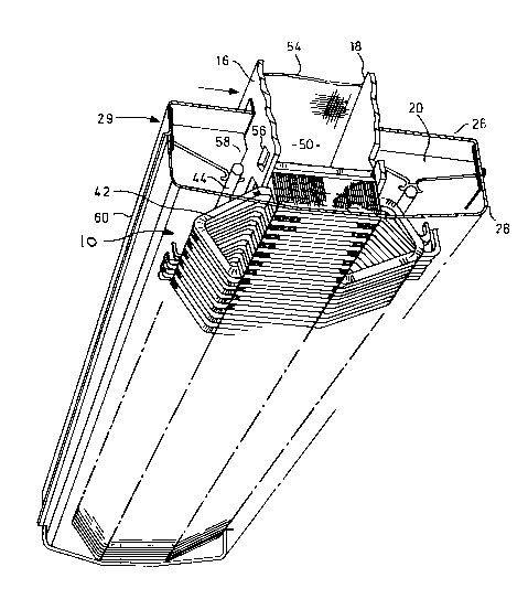
Figure 1 is a perspective view of a linear
induction motor primary;
Figure 2 is a perspective view of the motor of
Figure 1 taken from the underside with portions removed
for clarity;
Figure 3 is a view on the line 3-3 of Figure 1;
and
Figure 4 is a view on the line 4-4 of Figure 3.
Referring now to Figures 1-3, a primary of a
linear induction motor 10 comprises a core 12 supported
in a
_ ~-
~ r ~

- 2034277
-- 3
frame 14 for attachment to the underside of vehicle (not
shown). The frame 14 comprises a pair of longitudinal frame
members 16,18 and outriggers 20 extending laterally from
each side of the frame members 16,18. Outriggers 20 serve
to support the side covers 26,28 that define a housing 29 on
either side of the core 12.
The core 12 is formed from a plurality of
longitudinal extending laminations 30 which are secured to
the frame members 16,18 by bolts 32. The bolts 32 are
located at spaced intervals along the length of the frame
members 16,18 and serve to hold the laminations in close
proximity. As can best be seen in Figure 4, each of the
laminations 30 has a series of rectangular slots 34 spaced
along its length to accomodate motor windings 36. The
windings 36 are helically wound in a three-phase winding as
more fully described in the above referenced U.S. Patent
4,642,493. The windings 36 are secured within the slots 34
by keys 38 co-operating with dovetail formations 40 at the
lower end of each of the slots 34. As can be seen in Figure
2, each of the windings 36 projects laterally beyond the
core 12 and has direction reversing end turns 42 supported
within the covers 26,28 by a circular longitudinal bar 44
secured to the outriggers 20.
Referring once again to Figure 1, a fan 46 is
mounted above the core 12 and between the frame members
16,18 and serves to provide cooling air to the upper surface
of the core 12. Fan 46 delivers cooling air through a duct
48 into a plenum 50 extending the length of the primary.
Duct 48 is located as close to the centre of the core 12 as
practical to assist in uniform air distribution. Plenum 50
is defined between the frame members 16,18, the upper
surface of core 12, and a cover 52. A diffuser screen 54 is
located in the plenum between the upper surface of core 12

203~277
-
-- 4
and the cover 52 to distribute uniformly air delivered
through the duct 48.
The side frames 16,18 each have a series of
apertures 56 uniformly spaced along the length of the
primary and allowing communication between the plenum 50 and
housing 29. In order to provide cooling flow of air over
the end turns 42, a deflector plate 58 is located between
o each outrigger and extends from the side frames 16,18 to the
side covers 26,28. The baffle 58 has a portion 59 extending
outwardly and downwardly from the respective frame members
16,18. The portion 59 extends from above and across the
apertures 56 so that air passing through the apertures is
deflected downwardly between the end turns. Baffle 58 is
supported between the outriggers 20 by the bar 44 that co-
operates with the baffle 58 to provide a barrier extending
the length of the core 12. This ensures that air passing
through the apertures 56 passes between the end turns 42
before exiting the housing by elongate exhaust slots 60 in
the side cover 28. The location of the slots causes the air
to flow upwardly and outwardly from the housing 28 and at
the same time inhibits ingress of water and dust. Baffle 58
and bar 44 are formed from a non-conducting material such as
fibreglass laminations.
To promote efficient cooling of the core 12 and as
may be seen in Figure 4, each of the laminations 30 is
formed with a castellated edge 62. Accordingly, when the
laminations 30 are assembled and installed between the frame
members 16,18, alternating transversely extending
passageways 64 and fins 66 are formed in a direction
parallel to the slots 34. The castellations 62 provide an
increased surface area for the upper surface of the core 12
and direct air to flow through the passageways 64 toward the
apertures 56. Apertures 56 are positioned to overlap the
., j,

2034277
,
-- 5 --
fins 66 and thereby cause the air to flow along the
passageways 64 to the housing.
In operation, therefore, air supplied from the fan
42 is uniformly distributed over the upper surface of core
12 by the diffuser. The surface area of the core 12 is
increased by fins 66 to improve the heat transfer to the air
that flows out of plenum and into the housing 29 through
apertures 56. The efficient cooling of end turns 44 is
provided by the deflector plates 58 which cause the air to
pass between the end turns as it moves to the exit slots 60.

Dessin représentatif
Une figure unique qui représente un dessin illustrant l'invention.
États administratifs

2024-08-01 : Dans le cadre de la transition vers les Brevets de nouvelle génération (BNG), la base de données sur les brevets canadiens (BDBC) contient désormais un Historique d'événement plus détaillé, qui reproduit le Journal des événements de notre nouvelle solution interne.

Veuillez noter que les événements débutant par « Inactive : » se réfèrent à des événements qui ne sont plus utilisés dans notre nouvelle solution interne.

Pour une meilleure compréhension de l'état de la demande ou brevet qui figure sur cette page, la rubrique Mise en garde , et les descriptions de Brevet , Historique d'événement , Taxes périodiques et Historique des paiements devraient être consultées.

Historique d'événement

Description Date
Inactive : Périmé (brevet - nouvelle loi) 2011-01-16
Inactive : TME en retard traitée 2010-01-22
Lettre envoyée 2010-01-18
Inactive : TME en retard traitée 2009-03-16
Lettre envoyée 2009-01-16
Inactive : CIB de MCD 2006-03-11
Inactive : Regroupement d'agents 2003-02-05
Inactive : TME en retard traitée 2001-02-02
Accordé par délivrance 1997-03-18
Demande publiée (accessible au public) 1992-07-17
Exigences pour une requête d'examen - jugée conforme 1991-08-23
Toutes les exigences pour l'examen - jugée conforme 1991-08-23

Historique d'abandonnement

Il n'y a pas d'historique d'abandonnement

Historique des taxes

Type de taxes Anniversaire Échéance Date payée
TM (brevet, 7e anniv.) - générale 1998-01-20 1997-12-17
TM (brevet, 8e anniv.) - générale 1999-01-18 1999-01-12
TM (brevet, 9e anniv.) - générale 2000-01-17 1999-12-16
TM (brevet, 10e anniv.) - générale 2001-01-16 2001-02-02
Annulation de la péremption réputée 2010-01-18 2001-02-02
TM (brevet, 11e anniv.) - générale 2002-01-16 2002-01-11
TM (brevet, 12e anniv.) - générale 2003-01-16 2002-12-17
TM (brevet, 13e anniv.) - générale 2004-01-16 2003-12-23
TM (brevet, 14e anniv.) - générale 2005-01-17 2004-12-22
TM (brevet, 15e anniv.) - générale 2006-01-16 2005-12-23
TM (brevet, 16e anniv.) - générale 2007-01-16 2006-12-19
TM (brevet, 17e anniv.) - générale 2008-01-16 2008-01-11
TM (brevet, 18e anniv.) - générale 2009-01-16 2009-03-16
Annulation de la péremption réputée 2010-01-18 2009-03-16
TM (brevet, 19e anniv.) - générale 2010-01-18 2010-01-22
Annulation de la péremption réputée 2010-01-18 2010-01-22
Titulaires au dossier

Les titulaires actuels et antérieures au dossier sont affichés en ordre alphabétique.

Titulaires actuels au dossier
BOMBARDIER INC.
Titulaires antérieures au dossier
DAVID GILMORE
JOHN STANNARD
KURT VOLLENWYDER
Les propriétaires antérieurs qui ne figurent pas dans la liste des « Propriétaires au dossier » apparaîtront dans d'autres documents au dossier.
Documents

Pour visionner les fichiers sélectionnés, entrer le code reCAPTCHA :


Pour visualiser une image, cliquer sur un lien dans la colonne description du document. Pour télécharger l'image (les images), cliquer l'une ou plusieurs cases à cocher dans la première colonne et ensuite cliquer sur le bouton "Télécharger sélection en format PDF (archive Zip)" ou le bouton "Télécharger sélection (en un fichier PDF fusionné)".

Liste des documents de brevet publiés et non publiés sur la BDBC .

Si vous avez des difficultés à accéder au contenu, veuillez communiquer avec le Centre de services à la clientèle au 1-866-997-1936, ou envoyer un courriel au Centre de service à la clientèle de l'OPIC.


Description du
Document 
Date
(aaaa-mm-jj) 
Nombre de pages   Taille de l'image (Ko) 
Description 1997-02-26 6 236
Revendications 1997-02-26 5 156
Page couverture 1997-02-26 1 14
Abrégé 1997-02-26 1 15
Dessins 1997-02-26 4 101
Dessins 1994-03-13 4 95
Abrégé 1994-03-13 1 12
Page couverture 1994-03-13 1 12
Revendications 1994-03-13 2 47
Description 1994-03-13 5 156
Dessin représentatif 1999-07-07 1 29
Quittance d'un paiement en retard 2001-02-12 1 169
Avis concernant la taxe de maintien 2009-03-02 1 171
Quittance d'un paiement en retard 2009-04-03 1 163
Avis concernant la taxe de maintien 2010-02-15 1 170
Quittance d'un paiement en retard 2010-02-15 1 163
Taxes 1999-01-12 1 33
Taxes 2001-02-02 2 71
Taxes 1999-12-16 1 31
Taxes 2008-01-11 1 27
Taxes 1996-12-12 1 37
Taxes 1995-12-18 1 38
Taxes 1994-12-01 1 41
Taxes 1994-01-07 1 31
Correspondance 1993-03-08 1 14
Taxes 1993-01-04 1 34
Correspondance de la poursuite 1991-01-16 9 331
Correspondance de la poursuite 1991-08-23 1 24
Demande de l'examinateur 1996-02-20 1 51
Courtoisie - Lettre du bureau 1991-11-19 1 33
Correspondance reliée aux formalités 1997-01-07 1 40
Correspondance reliée aux formalités 1992-04-30 2 40
Courtoisie - Lettre du bureau 1992-05-01 1 29
Correspondance reliée aux formalités 1996-06-07 1 24
Correspondance reliée aux formalités 1996-07-04 1 14
Correspondance reliée aux formalités 1996-07-04 1 20
Courtoisie - Lettre du bureau 1991-05-17 1 35
Correspondance de la poursuite 1996-08-14 3 74