Note : Les descriptions sont présentées dans la langue officielle dans laquelle elles ont été soumises.
2035322
This invention relates to a snow disposal or manipulation
system and a method therefor.
In cities and towns where snow is ploughed from the
streets or similar areas, and subsequently collected for
disposal, it is generally the norm that the snow is collected
by a snow blower or loader and placed into trucks, which then
transport the collected snow to land sites where it is dumped
and permitted to melt during warmer weather.
Snow removal has become a very expensive and time
consuming affair. In general, the collection and disposal of
snow can run into the millions of dollars each year even for
smaller cities and towns. To a large extent, the cost of snow
disposal relates to the cartage of snow from the streets to the
areas where it is to be stored or dumped. In modern cities,
since there is very little area for the snow to be dumped, it
must be transported significant distances to find vacant land
sites.
In the past, other alternatives have been considered such
as dumping of the snow at closer locations where there may be
a lake or stream. However, it is not as environmentally
desirable to do this since snow gathered from streets is
frequently polluted.
On the other hand, most cities have an underground sewage
system and as such, the underground conduits normally carry
large volumes of warm water or liquid, which may then be
treated at sewage treatment plants. Again, most cities have
a relatively large number of conduits extending throughout the
city infrastructure but such conduits, which connect the city
streets via manhole covers, are generally only small diameter
conduits, e.g. two to four feet or so. Up until now, it has
2 0 3 5 3 2 2
basically been impossible to be able to use the common type of
manholes and associated conduits since no means has existed for
loading or discharging snow from cartage vehicles into the
sewer systems.
Other proposals for disposing of snow have also included
devices for melting snow into the sewer system. In general,
cartage trucks will take a load of snow to a central point and
dump the load into large heated bins, which melt the snow using
electrical or fuel fired burners. Such a procedure is quite
costly in terms of energy consumption and is not economically
advantageous.
It would therefore be desirable if the conventional sewer
system could be employed to dispose of snow, thus reducing the
cartage distances and at the same time, eliminating snow build
up in vacant land sites.
According to this invention, and in one aspect thereof,
there is provided a snow disposal system comprising: snow
receiving means adapted to receive a charge of snow to be
disposed of; first grinding means for grinding the charge of
snow into a generally particulate form and for advancing the
same in a disposal direction; means for effecting a projection
o snow discharged by the first grinding means in a path
removed from the first grinding means; disposal means for
receiving projected snow from the last-mentioned means located
downstream in a direction in which the snow is projected by the
last-mentioned means, the disposal means including a conduit
having a liquid flow adapted to
'~J
_
20353~2
_ 3
receive and transport the disposed product away from the
disposal site.
In preferred embodiments of the present invention,
the disposal system includes receiving means adapted to
receive, e.g. truck loads of snow from street cleaning
operations. To this end, the receiving means may be a
bin-like structure in which the upper portion is
dimensioned so as to receive a load of snow which may be
discharged from a dump truck by backing up the truck and
emptying the snow into the bin, or in other cases, the
load of snow may be pushed by e.g. a bulldozer into the
bin. The bin will have a narrower discharge end,
dimensioned preferably in close proximation to the size
of a manhole opening connecting with a sewer system
conduit. Thus, the walls of the bin may be tapered to a
narrower throat section.
To prevent snow from adhering to the bin, the
material from which the bin is constructed of, e.g. sheet
metal, plastic, concrete, wood, etc., may be provided
with a coating of a suitable slippery substance such as a
silicon polymer, a "Teflon" polymer, etc. Alternately,
where the bin is made of e.g. metal or concrete, the bin
may be heated to prevent snow adherence or buildup
thereon. In a still further embodiment, where using
wood, metal or like bins, vibrating means may be employed
for the same purpose.
In a particularly preferred embodiment, the grinding
means include at least a pair of rollers having counter
rotating blades and means for driving said counter
rotating blades. It is preferred that the bin like
structure is generally vertically oriented relative to
Z035~
the grinding means and the grinding means is located
beneath the bin.
Suitable grinding means may be e.g. one or more
pairs of counter rotating blades, two or more rotating
augers, or the like. It will be understood by those
skilled in the art that any suitable grinding means may
be employed.
In this respect, the grinding means need not
necessarily be located within the bin like structure but
rather, can be disposed exteriorly thereof beneath the
discharge opening of the bin like structure.
In another preferred aspect, the means for effecting
the projection of snow is disposed directly below the
grinding means and is adapted to project ground up snow
from said grinding means in a generally vertical
trajectory into a conduit of the sewer system which has
liquid therein. Typically, such means may be in the form
of an impeller or like assembly which receives the snow
and by means of one or more high speed blades, the snow
is projected with high velocity downwardly into the
conduit and sewer system.
The impeller means may have separate drive means
associated with it, relative to the drive means for the
grinding component. If desired, however, similar drive
means which drive the grinding means may be geared to the
impeller means for this purpose.
In a particularly preferred embodiment of the
present invention, the system includes sensing means
which controls the speed of the motors for the grinding
Z0353;~2
_ 5
means. To this end, the grinding means are preferably
driven by variable speed motors, or alternately, constant
speed motors may be employed using variable speed
mechanical gear or gear reducing means to control the
speed of the motor. In turn, the variable speed motors,
or constant speed motors with variable speed gears and
the like, can be controlled by control means responsive
to sensing means. The sensing means preferably sense the
absorption capacity of the liquid into which the snow is
absorbed; thus, sensing means for measuring the heat load
of the liquid can be employed. Such sensing means may
take various forms but e.g. temperature and flow sensing
means can be employed for this purpose.
In addition, sensing means are also preferably
employed to sense any blockage in the trajectory path of
the snow. Such sensing means can be electronic to
determine whether snow forms a blockage in the conduit.
By using the sensing means, the speed of snow
disposal can be varied to fit the particular sewage
system which is used for snow disposal, at any time
during the night or day. Thus, where the load bearing
capacity of the liquid is limited due to low
temperatures, predetermined rotation of the motors will
permit discharge only of the quantity of snow that can be
absorbed.
According to another aspect of this invention there
is also provided a method of snow disposal comprising:
providing snow receiving means adapted to receive and
charge of snow to be disposed of; grinding said charge
of snow into a generally particulate form; advancing the
ground snow in a disposal direction; projecting snow
2035;~
discharged by said grinding step in a path spaced from
said grinding step; disposing of said snow in a disposal
means for receiving projected snow downstream in a
direction from which said snow is projected, said snow
being disposed of in disposal means including a conduit
having a liquid flow adapted to receive and transport
particulate snow away from the disposal site.
In a preferred method, the snow is initially charged
into a bin like structure which is adapted to receive
snow to be disposed of. Further, there may be provided
means for preventing snow charged to said structure from
adhering to said structure; to this end the method may
include the step of heating one or more parts of the
structure or in an alternative embodiment, the method may
include the step of coating the structure with a coating
adapted to prevent the snow from sticking thereto.
In preferred method embodiments, there is also
included the step of sensing the load carrying capacity
of the liquid into which the snow is to be discharged in
order to determine the load carrying capacity of the
liquid and then altering the feeding step and grinding
step to coordinate the same with the load bearing
capacity of the liquid so as to avoid overloading the
liquid capacity to absorb the snow.
Having thus generally described the invention,
reference will now be made to the accompanying drawings,
illustrating preferred embodiments and in which
Figure 1 is a vertical elevational view, partially
in section, showing a typical sewer system utilizing the
device of the present invention; and
- 2 0 3 S 3 2 2 1
Figure 2 is a diagrammatic representation showing trans-
porting and placement of the system of the present invention.
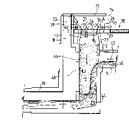
Referring now to Figure 1, an example of a sewer system
as may be encountered in many cities includes a main or primary
conduit indicated by reference numeral 10, which may lead to
a collector system for the overall sewer system or which may
be a side branch conduit feeding into a primary conduit.
The underground conduit 10 is normally connected to
vertically oriented conduits 12 which are of a generally
cylindrical configuration; there may also be included
intermediate conduits 14 feeding into the vertical conduit
where liquid sources are then discharged into the conduit 12
and thence to conduit 10.
In some cases, the sewer system will also include access
or vent conduits such as conduit 16 associated with another
smaller conduit 14.
Conduit 12 terminates, at a surface level indicated by
reference numeral 18 generally in a rimmed circular or
rectangular opening, which includes normally a steel or metal
rim 20 connecting a manhole opening to the conduit 12 via a
tapering collar 22. As indicated previously, such openings
normally are between two to four feet in diameter.
The system of this invention includes a mobile snow
grinding and projection system indicated generally by reference
numeral 24 and which includes a tapering bin-like structure 26
having walls extending downwardly into
B
Z035;~
a narrower throat portion 28. The walls 30 of the bin
like structure may include heating means 32 in the form
of electrical, gas or fuel fired burners or heaters, or
the like, which aid in preventing the snow from sticking
or adhering to the walls 30 of the bin like structure 26.
If desired, a grate may be provided over the bin 26,
which grate is indicated by reference numeral 27, to
prevent foreign objects from entering the bin. This
grate can be in the form of a suitable mesh or screen.
In the embodiment illustrated, located within the
bin like structure 26 are grinding means in the form of
rotating rollers 34 which carry blades 36 so that the
action of the blades 36, upon a load or charge of snow
placed into the bin like structure 26, is such that the
snow is ground into a particulate form.
Operating in conjunction with the grinding means is
an impeller assembly indicated generally by reference
numeral 38 which is driven by a motor 40. The impeller
assembly 38 may be a conventional assembly capable of
receiving particulate snow and projecting the same into a
downwardly extending trajectory into the conduit 12.
Drive means in the form of a pair of motors 42 are
provided for effecting rotation of the grinding means.
Such motors 42 are preferably variable speed motors or
constant speed motors connected to a variable speed
reducer, and control means in the form of a suitable
conventional switch will determine the speed of rotation
of the motors. Operating in conjunction with the switch
for controlling the speed of the motor are a pair of
sensors 44, 46, the first of which is placed within the
-
2 0 3 5 3 2 2
liquid in the sewer system and the second of which is placed
generally in the path of the ground snow. Sensor 44 is adapted
to determine the load carrying capacity of the liquid in terms
of its ability to absorb and carry snow placed in the liquid.
Sensor 46 is adapted to determine blockage of the conduit 12
in feeding the snow into the sewer system. Thus, both sensors
may be connected to the switch controlling the motors so that
upon a blockage occurring, the motors will cease feeding snow
to the impeller means 38, or on the other hand, when the load
carrying capacity of the liquid in the sewer system reaches a
maximum, the amount of snow being fed to the sewer system can
be reduced. Suitable conventional sensors 44 and 46 can be
used; in practice, sensors 44 and 46 may be connected to a
control panel which in turn, is coupled to a control switch for
controlling the speed of rotation of motors 42. Both sensors
44 and 46 may be placed in the sewer system either in a
permanent or temporary manner, depending on whether the same
manhole opening is to be used year after year.
The apparatus of this invention may be suspended or
mounted on suitable frame members 50 which are adapted to
surround the manhole opening, sit on the adjacent road or like
structure. Such frame members 50 can be a separate frame
structure and need not be part of the overall assembly.
In the system illustrated in Figure 1, where a side sewer
conduit 14 enters into a vertical conduit 12, liquid 60 gener-
ally flows in the direction of arrow 62 and falls to the bottom
of conduit 12 where it enters into the primary conduit 10. By
forcefully projecting
~7
Z035~;~2
-- 10
snow using the system of this invention downwardly in the
direction of arrow 64, the projected snow is mixed with
and absorbed by the liquid in the sewer system,
whereafter it is discharged into the primary conduit lo.
Referring to Figure 2, since snow disposal
operations are only intermittently required, the system
of the present invention can be transported by suitable
means, e.g. a crane, to a site where an appropriately
selected manhole and associated sewer system is to be
used. Upon termination of the snow disposal operations,
the system can then be transported to a storage place.
Of course, if desired, the system may be left in place
during the winter months.
Having described preferred embodiments, it will be
understood that various modifications can be made to the
above embodiments without departing from the spirit or
scope of the invention.