Note : Les descriptions sont présentées dans la langue officielle dans laquelle elles ont été soumises.
~ W091/00231 PCT/E~0~00992
2~354~
TRASH COLLECTION VE~ICLE
__
The present invention relates to a trash collection
vehicle of the type which includes a collection container
disposed behind an operator station, particularly behind the
driver's cab of a motor vehicle. The collection container,
which is preferably releasable lrom ~he vehicle, has a fill
opening disposed in its upper region and at least one wall
portion which can be opened for emptying, preferably the
wall facing away from the fill openingO The type of trash
collection vehicle to which the present invention relates
a~so includes means ~or compacting the waste filled into the
collection container.
A trash collection vehicle of the above-mentioned type
is disclosed in U.S. Patent 3,202,305 to George R. ~empster
and another. The trash containers are picked up from the
ground at the front of the vehicle ahea~ of the driver's cab
by a pair of pivot arms which are connected with the
collection container. The trash containers ~re then pivoted
high above ~he driver's c~b and emptied into the fill
` ~ 20 opening o~ the collection container disposed behind the
driver's cab by~tipping them over. A significant drawback of
these vehic~les, known as i'overhead loader~," is that during
pivoting o~ ~hé trash containers for emptying i~to the fill
opening a~ the top of;the collection container~ the n~rmal
25 ~ clearance pro~ile of such vehicles is exceed~d considerably.
. ~ ~
The term "clearance profile'^ as used herein means the height
SUE35TITUTE SHEET
`
WO91/00231 2 PCT/EP90/00992 ~ ~Is
20354~8
of the vehicle at its highest point when trash is not being
transferred.
U.S. Patent 4,096,959 ~o Georg Schaffler further
discloses a trash collection vehicle in which a receiving
hopper is disposed on the chas~is between the driver's cab
and the collection container, wnich is relea~ably connected
with the vehicle. The trash containers are emptied into this
receiving hopper by a pair of pivot arms which flip them over
in the manner of an overhead loader. The trash is then moved
by a shoveling device from the recei~ing hopper into the
fill opening at the top of the collec~ion container~
Compaction of the trash in the collection container is not
possible, so that optimum loading cannot be realized. Aside
from the above described dxawbacks of an overhead loader~
this vehicle has the further drawback that the arrangement of
the receiving hopper between the:~c~llection containex and the
driver's cab reduces the volume available for the collection
container to a considera~le degree.
U.S. Patent 3,643,824 to Har~ie C. Partridge discloses a
trash collection vehicle in~which a~receiving hopper is
disposed ~etween the driver's cab and the collection
containex, which is fixed to~the cnassis~but is tilta~lel.
The receiving hopper can be loaded manually from the ground
with small trash;containers or by way of an appropriate . -`
filling device. The trash di:sposed I~ the receiving happer
: is then pushed by a:pusher into the collection container
: ;: `:
ST3TUTE SH~ET ~-
;
~ WO9l/00231 PCT/EP90/00992
2 ~ 3 ~ 4 ~ ~
through an opening disposed in the bottom region of the front
wall of the collection container, and is substantially
compacted. Large trash containers can not be emptied.
SUMMARY OF T~HE_INVENTION
It is an object of the present invention to provide a
trash collection vehicle of the above-mentioned type which
utilizes the advantages known for an overhead loader, namely
the fact that the workers are able to operate in front of the
~ driver's cab in eye contact with the driver, and which avoids
the drawbacks of the above-described systems, while
permitting small-volume trash containers such as household
trash cans to be emptied.
This is accomplished according to the invention in that,
in the front region of the driveris cab, at least one
intermediate container is disposed~for recei~ing the trash
~rom trash containers. This intermediate container is in
communication with means for emptying the contents of the
intermedlate container into the f ill opening at the top of
the collection:container~ The intermediate container has a
discharge opening separate fr~m its fill opening. At least
durling the e~mptying process, the d;scharge open;ing bf the
intermediate container is in communication with the fill
:~ opening of ~he collection container.
: An advisable:further feature of the invention provides
~that the discharge opening of the intexmediate ~ontainer
,:
SU~STIT(~'~E S~^~ET
~' ~ t`~
W~91/0023l 4 PCT/E~0/00992 ~ ~ ~
203~5~
and/or the fill opening of the collection container are
olosable. In this way it is possible for the intermediate
container to have a closed configuration except for the
mentioned openings. The arrangement of such an intermediat~
container in the front region of the driver's cab has the
advantage that the space behind the driver's cab is available
for practically its entire length to accommodate the
collection container, which can thus be of the largest
possible size. The term "front region" in the sense of the
invention includes the space in front of the driver's cab as
well as the space above the driver's cab.
A further advantage of a vehicle a~cording to the
invention, compared to conventional trash collection
vehicles, is that its weight distribution i5 better, since
the weight of the components required for manipulating the
trash containers and the intermediate container is absorbed
by the front axle of the vehicle. A~cordingly, the region
at the rear axle is available to the fullest extent for
accommodating the load provided by the filled colle~tion
~ontainer. This results in better load distribution.
:
A further advantage of a trash collec~ion vehicle
conf igured acc~rding to the invention is that the
intermediate container is emp~ied through an ope~ing at the
;~ top~of ~he collection container so:that, in conjunction wi~h
: 25 a compaction device such as a pusher, optimum filling of the
: ~
~ coll:ection container is possible. The filling from the top ij~
L~
'
~ SW~3$TlTl~TE SHEET
~ WOgl/00231 5 PCT/EP90/00992
~3~
is of particular significance for the compaction process
since the ~uantities of trash received in the fill opening of
the collection container by way of the intermediate containe~
are pushed together a~ainst the opposite end wall and are
compacted below the ceiling of the container. The
compacting device i5 preferably configured in such a manner
that it essentially covers the entire container cross
section.
Sufficient space for maneuvering the vehicle must always
be available ln the direction of travel, so sufficient room
is ensured for manipulating the trash containers, and eye
contact can easily be established between the driver and the
operating crew. The workers can give a signal ~o mo~e on to
the next pickup location, for example, once they have
climbed onto the vehicle.
A trash collection ~ehicle according to the invention is
of such design that it can be constructed to particular
advantage on the basis of a mass-produced chassis. The trash
collection vehicle may also be configured as a special
20 vehicle with a so-called dropped frame design which has only
a slight clearance above the ground. This makes it possible
~ I` i " I ' ~ ' ~
to provide a low lying driver's cab and/o~ a ~ow lying
chassi~s so that a relatively great height is available for
the intermediate container and the collection container~
SUE35TITUTE 5HE~T
WO9l/00~31 PCT/EP90/00992 ~
2 9 3 ~ ~ 5 1~ !
without exceeding the maximum pe~missible height during
emptying~ This makes a large capacity available.
A preferred feature of the invention provides that the
intermediate container is in communication with at l~ast one
device for manipulating the trash containers to be emptied
into it~ Depending on the configuration and/or arrangement
of the intermediate container, a device for manipulating
trash containers may include a con~entional, pivotable trash
container holder mechanism~ as they are employed for the
Io manipulation of household trash cans ha~ing a volume b2tween
50 and 240 liters and/or also for the manipulation of large
containers having a capacity of 1 to 2 m3. While it is
possible, in principle, to configure the intermediate
container as an open container, it is ad~isable for it to be
a closed structure having a closable fill opening that can be
opened, for example, by way of the~holder mechanism. If only
a single intermediate container is provided, it ~ay be
connected with two or more holder mechanisms so that several
trash containers can be emptied simultaneously.
The intermediate container may b~ subdi~ided into at
least two container portions, with each container portion
ha~ing an a$sociated dischar~e ope~in~. This permits
discharge of sorted trash into the intermediat container
for subsequent transfer to a colle tion container that is
also subdivided in accordance with the invention. Each
SUBSTITUTE SHE~E~T
~; WO91/00231 PCT/EP9OJ00992
colltainer portion of ~he intermediate container may be
connected with its own holder mechanism for the trash cans.
It is also possihle ~o provide two separate intermediate
containers, which is of particular advantage for embodiments
which are equipped with a displacement apparatus for the
intermediate container. In this case, each intermediate
container has its own associated displacement apparatus and
can be moved independently of the other.
If the collection ~ontainer is subdivided, at least some
of the container portions may be releasably connected with
one another. This has the advantage that, ~or example,
household trash, which forms the major component of the
collected trash load, can be dumped into a large basic
container which acts as a supporting body f~r the releasable
container portions.~ Special trash can then be dumped
separately and sorted into the container portions. For
example, a large hospital or a remotely located treatme~t
facility can be served in only one trash removal trip. The
container por~ions with the special trash can then be
sepaxated from the normal waste without any reloading being
required. Glass or paper can also be trancported away in a
sorted manner together with the hous hold trash if it i5~ made
available appropriately pre-sorted. If an intermediate
container is provided, appropriate control at a displacement
2~ apparatus according to the invention permits the inter
mediate container to then be moved directly toward individual
:
~: .
~ ~ SUEiSTlTUTE SHEET
WO91~0023~ . PCT/EP90/00992 ~ j
2 ~ 5 ~ 1: oontainer portions of the collection container t~ be emptied
thereinto.
A preferred feature of the invention ~urther pr~vides
that the discharge opening of the intermediate container
5 and/or the fill opening of the collection container are - -~
provided with an extension which projects into the respec-
tive other opening at least when the intermediate container
is being emptied. This is advantageous particularly for
trash collection vehicles in which the intermediate container
0 and the collection container can be separated from one
another according to the invention, since a proper seal is
provided between the two mutually associated openings and no
trash is able to escape to the outside. Moreover, such an
extension which enters into the respective other opening
makes it possible to seal the transition region.
As an advantageous feature of the invention, it is
further provided that at lea~t one wall portion extending
transversely to the longitudinal axis of the collection
container is displ~ceable in the longitudinal direction of
the container and is in communication with an actuation
mechanism (pre~erably operated hydraulically) which acts on
the displaceable wall portion. The wall portion may be ~
container wall hut it may also be a pressing plate or pusher
which lies against the con~ainer wall. It i5 advantageous to
mount the pusher~ at the end of the collection container
faciny the dri~er's cab because considerable sa~ings in
~: :
SU~STITLITE SH~ET
, j!~,~, .~ WO 9l/00231 PCT/EP90/0~9g2
,.. ., ~:
2 ~ 3 ~v ~ 5 ~
weight for the container can be obtained since the actuation
mechanism for the pusher can be arranged at the ~ehicle and
no hydraulic components need be provided in the collection
container for compactin~ the trash. Accordingly the entire
hydraulic system can be fixedly installed in the vehicle. A
releasable coupling must be provided between the
displaceable wall portion of the collection container and the
actuation mechanism (preferably a telescoping hydraulic unit)
if the collection container is confi~ured to be releasable.
10 During operation, the actuation unit provldes a forward and
return movement required for compaction ~ia the releasable
coupling. Moreover, this has the advantage that relati~ely
small trash collection vehicles which are able to move
: through narrow streets can be employed. Particularly for
this use, the arrangement of the intermediate container and
its filling by way o~ ~he ~ill opening at the ~ront region of
<!~ .
the vehicle is o~ advantage because of its better
maneu~erability. A filled collection container can then be
deposited by the trash collection vehicle while it is stilI
within its assigned region ~nd an empty new container c~an be
~eceiv~d as a replacement so that:the trash collection
vehicle and its operating crew~need travel only in the~ ,~
collection àreaO The filled collection containers can thein
: be transported away by other vehicles which are able to
25: transport~several such~collectlon~containers by road or by
railroad to more~distant depositories~ It is important tha~
:
SUBSTITUTE S:HE~T
WO91/0023l PCT/EP90/~0992 ~;
2 ~ 3 ~ ~eloading of the trash is necessary. Rather, the filled
collection containers are merely set down one place and are
then picked up again for further transporting. Depending on
their siæe, the transporting ~ehicles can transport one or
more such collection containers, and a trailer filled with
collection containers can be employed.
It is advisable for the ccll~ction container to be ::
e~uipped with extendable ground supports. This makes it
possible to employ a con~entional truck chassis equipped for
operation with so-alled interchangeable bodies for the above
described transport of collection containers. Both filled
and empty collection containers can be transported by
vehicles designed for purely highway traffic. If, fox
example, the trash is driven to a waste incineration system,
a filled collection container can be deposited there on a
tilting device, can be emptied, and can be picked up again by
the transporting vehicle.
In one embodiment of a trash collection vehicle
according to the invention, the intermediate container is
~0 disposed above the driver's cab and a device for
manipulating the trash containers or dumping device is
conigured as a pivotable holder mechanism and is equipped
wi~h a pickTup dr elevating mechanlsm for the tra~h
containers to be emptied, with such elevating mechanism
:25 extending into the bottom region in front o~ the driver's
cab. This arrangement has the advantage that a relati~ely
SlUiB~iTlTaJlTE S~ ET
.
~ WO 91/00;!31 ^ Pl'/EP90/OOg92
~! 2~5~
large capacity intermèdiate container can be employed. Two
or more such dumpin~ devices may be provided so that several
trash containers can be manipulated independently and
simultaneously. If the intermediate container is accessible
from its frontal face, the tilting of the trash containexs
caused by the dumping can be effected in such a manner that
the clearance profile is not exceeded substantially. During
operation, the driver's view is not obstructed. The
arrangement ~f the intermediate container above the driver's
cab also permits the use of a driver's cab having a second
~ seating bench for the operating crew so that, for longer
trips between stops, for example in spread-apart residential
areas, the crew is able to enter the vehicle from the front,
that is, within the driver's viewing range.
As a further feature of the invention it is pro~ided
that the intermediate container above the driver's cab may be
movable back and forth along a guiae from a forward posltion
into an emptying position at the collection container. This
confi~uration i5 of advantage, in particular, if the collec-
tion container and/or khe i~termediate container are parti-
tioned into several portions. Th~ intermediate container can
then directly approach the associated fill opening of the
colleckion container.~ The guide may be~configured in uch a
manner that one portion o~ the guide~is disposed.above the
driver's cab and is fixed to the chassis and another portion
of the gUidQ is fixed to ~he collectiQn containerr This
SU3~T~TUTE S~E~ET
~ ~ .
WO91/00231 12 PCT/E~0/0099~ ~ i
-` 2035~
advantage also exists if two independently movable
intermediate contain2rs are employed.
In another preferred embodiment of the trash collection
vehicle according to the invention, a displacement apparatus
for the intermediate container is connected with the vehicle
so as to move the intermediate container over the driver's
cab from a ~ill position on or near the ground in front of
the driver's cab to the intermediate container's emptying
position at the collection container. This configuration has
O the ad~antage, inter alia, that the dimensions of the
intermediate container may extend almost over the entire
width of the vehicle and approximately over the length of the
driver's cab so that a large capacity intermediate container
can be employed. In the fill position, this intermediate
container can also be filled manually with trash b~gs and
small trash containers. Howe~er, by way of an appropriate
holder mechanism associated with the intermediate container,
conventional trash containers can also be emptied~ The
: particular advantage here is that little work needs to be
per~ormed to empty the trash containers into the collec~ion
~ container, and consequently the trash containers are emptied
: fas~er. Since the displacement apparatus permits the
intermediate container to be brought close to the ground,
the shortening of: the lif~ing path connected therewith aIso
~: 25~ simplifies the deslgn of the holder mechanism. As soon as
,
the lntermediate container is filled completely, it is lifted
.
~ ~ SUBST~TUrE~ SHEE~T
1~ W091~00231 13 PCT/E~0/00992
2 ~ 5 ~
with the aid of the displace~ent apparatus to the height of
the roof of the driver's cab. The intermediate container is
then moved to the fill opening of the collectlon container
behind the driver's cab and is there emptied with the aid of
its emptying means. Although the intermediate container is
still in its emptying position, the trash collection vehicle
is able to move on to the next pickup location. The
intermediate container can then be moved back to its pickup
position near the ground by the displacement appara~us. In
an arrangement where the intermediate cont~iners can be moved
independently of one another, each intermediate container has
an associated displacement apparatus.
The ~isplacement apparatus for the intermediate
container may include a lifting mecha~ism disposed in front
~ of the driver's cab for an essentially ~ertlcal lifting
movement, and a driving de~ice for an essentially hori20ntal
(and pref~rably longitudinal) movement above the~driver's
;;,
cab~ This conf i~uration has the advantage that the movement
of the intermediate container is composed of only an
essentially vertical li~ting component and a movement
component in an essentially horizontal plane. In contxast to
h~ large pivot a~ s of the prior art overhèad loaders, the
prescribed clearance profile is~not exceeded~any time during
movement of the~intermediate container. This-makes i~
:
possible to perform all functions without any obstruction
even in cove~red entrances, under~overhead stree~car contact
SUBSTITUTE SH~ET
WO91/00231 . 14 PCT/EP90/00992 ~
2 ~ 3 5 1 5 ~ !
lines, or under trees. The lifting mechanism may, for
example, include a carriage which can b~ moved vertically up
and down in front of the dri~er's cab by a lifting drive or
by appropriately arranged pivot levers which raise the
intermediate container only to the level of the horizontal
plane of movement. In this connection, it may also be
advisable to provide~a carriage guide for the basic movement
of the carriage and, in view of minimum clearance with the
ground, to perform the final movement during lowering of the
inkermediate container to the ground region by means of
pivot levers. The movement in the horizontal plane may be a
pivoting movement by which the intermediate container is
pivoted about a vertical axis above the driver's cab directly
into it5i mptying position. If required, the Intermediate
container can be push~d a~ter the pivoting or it can be mo~ed
following the lifting~movement by means of a horizontal
pushing movement along a guide which extends ~o the region
of the fill opening of the collection contai~er.
As a further advantageous feature of ~he in~ention,
drive means are provided which~move the intermediate co~-
tainer along the guide to th~ emptying position a~ the
~;l` col1ectionicontainer and bac~ again. Thi 5i arrangement has
the advantage that, in spite~of the relative mobility of the
in~ermediate container along the guide, ~he intermedlat2
container can be fixed in~its direction of ~ove~ent by way of
the: dri~e m~ans and remain connected with ~he trash
S~IBS~ITUTE SH~ET
:
WO91/00231 PCT/EP90/OQ992
- 2~3~
collection vehicle The drive means may include, for
example, horizontally acting hydraulic cylinders, revolving
endless chains, or a driven carriage which recei~es the
intermediate container The underside of the intermediate
container may be guided while resting on the guides or, by
way of appropriate connecting means, the intermediate
container may be suspended~from the guides at its upper side
~r laterally~
;::
: In a particularly advisa~l;e ~configuration of an arrange-
ment which includes an apen intermediate :ccntainer, a
. .
pressure plate is displaceable along~the horizontal gulde so
as to close the opening of the intermediate container when it
is in the raised position This has ~the advantage that,~for ~;
~` ~ example, if the intermediate c~ortainer is loaded with bulky
trash or with trash bags, the~intermediate container is
closed~for the horizontal movement following the lifting
,,
movement and thus no parts projecting from the~buIky trash;or;~
tr-;sh~bags ar~ able~eo~interfere~with its~operation The
pressure plate~ may ~be configured~in~such a manner~that~it
20 : ~also carrle5~the~intermédiate~container by way~;~of~releasa~le~
connecting~me~ans~and~thus fo~ms~a~carriage which ~is iD ;
coDuni`cation with the dri~,re means~ ~ for example hydraulic~
c y 1 i n d e r s
A~s~an~ad~ant~geous~urther`feature~of~the;inventi~on~,~ the~ ;~
25~dis~charge~opening~of~the~intermediate~contaln~er~may be~
rovided ~l~h a~ lackable: closure. ~Actuatlng means ~ro=
W091/0~231 l6 PCT/E~0/~992 ~ ! ,
2~3~6
opening the lock are disposed at the guide in the region of
the emptying position at the fill opening of the collection,
container. If the intermediate container is subdivided into
several container portions, each container portlon may be
provided with an appropriate closure which can be opened only
at the associated fill opening of the collection container. ,
The disoharge opening of the intermediate container may
be disposed at its rearward end, with a discharging
apparatus which is mo~able toward the discharge opening
being provided as an emptying means in the intermediate
container. This`configuration of the intermediate container
can be employed ~or an intermediat :container which is
fixedly disposed above the driver's cab or f or an
intermediate container that is movable by way of a
displacement apparatus. Depending on the configuration of
the intermediate container, the discharging apparatus may
also be e~ployed to partially cqmpact the trash in the
intermediate contai~er. For emptying, the discharging
apparatus then pushes the trash through the discharge opening
into the ~ill opening in the upper region of the collection
container. A discharging apparatus in the sense of the
, ` present invention may be a movable push plate as wel1 as a
rolling or~scraper floor or a 50-called;~push-rod~floor in the
intermediat~ container. The factor:of primary importance in
:~ 25 this co~nection :i5 that the~quantities of trash falling into
::`: : ~: :
~:
UBSTlTlJ~E S~ ET
~ WO91/0023l 17 PCT/E~0100992
2~3!~45~S
the intermediate container are moved towards its discharge
~p~ g.
The discharge opening may alternatively be disposed at
the bottom of the intermediate container. This arrangement
has the advantage that the displacement apparatus is able to
bring the intermediate container to a position where it lies
closely above a fill opening in the ceiling of the~collection
container. After the closure is op~ened, the trash is able to
drop directly from the intermedlate container into thè
collection container.~ This arrangement is of partlcular
advantage for intermediate containers that are subdivided
into container portions and/or for subdivided collection
.
containers since the intermediate container can be~moved aver
~he collection container until it reaches the associated
,
15~ fill op~ning. By arranging approp~iate sealing means at the~
;~ lower edge o~ the intermediate conta~iner andjor at the;edge
of the fill openi~g of the collection container~,~for example~
. .
; in th~e form of;~a continuous rubber~bead, a good~seal can be
: ~ ~ ` obt~ined.
~ ~20~ A further~advantageoDs ~eatur~e~of~;ehé inventlon pro.ide~
;` that the~ displacement apparatus may be is ,disposed at a}
supporting frame which is:connected with the ~ehi~le ch~ssi
The supporting;~frame carriec the lifting mechanism in the~
front and~carries the~guide~and the~drive;means for~the
25~ ~intermediate ~ont~ainer~ i~D the~r~gion above the~driver's cab.
This~arrangement has~the advan~age tha~t~the displacement
SUBSTITUTE SHEET
WO9l/00231 18 PCT/EP90/00992 ~
`` ` 2~3~15~ `
apparatus forms a closed system in itself which is releasably
connected with the vehicle. Accordingly, after the
displacement apparatus h~s been removed, i~ is possible to
use the vehicle also for other transporting purp~ses.
A preferred feature of the invention provid~s that one
end of the supporting frame, preferably the end in front of
the driver's cab, is supported on the chassis at least two
front fastening points. A~ its other end, preferably the
end disposed behind the driver's cab, the supporting frame is
supported at least by one rear fastening point, which is
preferably disposed on the longitudinal center plane of the
vehicle. The supporting frame is inheren~ly rigid, and this
arrangement permits the supporting frame to be fastened in
such a manner that buckling of the chassis during operation
is possible without adverse effects. Another advantage of
this configuration is that the supporting frame can be
fastened in the front region at the ends of the chassis that
are easily accessible, and are configur~d on conventional
trucks for the connection of additional assemblies.
The rear fastening point is preferably formed by a joint
having at least two d~rees of freedom. The joint may be,
~, ; for example, a ~niversal joint, a ball joint, or a flexible
rubber joint.
~: Another feature~of the in~ention provides that the rear b
fastening point may:be releasable and the ~upporting frame
~ may be mounted so as to be pivotal a~out a horizontal axis at
SUBSTITIJT ~à~lE~T
~ P~ WOgl/00231 19 PCTlE~0/00992
2~3~3~` :
its front fastening points. This configuration permits so-
called forward control vehicles, in which the dri~e motors
lie partially within the driver's cab and the driver's cab
can be pivoted forward for purposes of repair, to be used as
trash collection vehicles. If engine repair is necessary,
the supporting frame can be pivoted forward to permit the
driver's cab to be pivoted so that the engine can be
repaired. It is particularly advisable for the supporting
frame to be equipped with a controllable pivot drive,
preferably at least one hydraulic cylinder. In this way, the
supportin~ frame can be pivoted completely forward to enable
the driver's cab to be tilted as well. Furthermore the
supporting frame can be pivoted~by only a slight amount, so
that sufficient f ree space is availa~le for exchangins
collection contalners. This results in the additional
advantage that, assuming that the ~ill opening of the
collection container i~:at the top, the ~ill opening of a
collection container attached to the vehicle will be tightly
sealed against the outside at the supporting ~rame in the
region of the transfer point when the supporting frame is
: ~ loweredO In this connection, it is advisable ~or ~he
I i ~supporting,frame`to be releasably connec~ed with the chlassis.
: ~nother advantageous ~eature of the inven~ion pro~ides
~ : tha~, at least in ~he:region extending over the driver's cab,
: ~
the supporting frame includes~a guide which is enclosed on
: all sides except::for an entrance opening for the intermediate
~ ~ ~ sU3s ~ IT~ S~EE~
WO91J00231 PCT/E~0/00992 ~ '
~` ~ 3 ~
container and a transfer opening that can be connected to the
fill opening of the colle~tion container. This configuration
has the advantage that, once the lifting movement has been
completed, the intermediate container is conducted on its
horizontal path in a manner encapsulated against the outside.
There is a practicaIly dust-tight seal toward the outside,
and in particular the fill opening of the collection
container is sealed in the emptying region for the
intermediate container, and thus the intermediate container
1.0 can be emptied without adversely affecting the environment.
Another advantageous feature of the invention provides
that a cover may be disposed at the guide, with the cover at
least partially enclosing the space in front of the driverls
cab between the guide and the intermediate container, in its
fill position on the ground. The length of this cover is
variable to correspond to the lif~ ng mov~ment of the
intermediate container. This has the ad~antage that, for
intermediate containers that are open at the top, the trash
containers ~an be emptied while~the intermediate container is
: 20 substantially shi~lded from th2 outside. The forward region
of the cover, through which the trash container must ~ moved
y,the holding apparatus during dumping! is~preferably i
configured as a:str:ip curtain or the like. T~e strip curtain
is mounted at the guide by way of a winding device so that
2~ . its length can be shorten2d cor~esponding to the lifting
-
~ movement. The side and rear regions of the cover may also be
:
; ~ : SUgSTITlJ I E SHEET
~ :
~ WO9l/00231 21 PC~/EP90~00992
2~3~
formed by such windable curtains. However, a bellows which
encl~ses the side and rear regions in a tightly sealing
manner and which has an approximately C-shaped cross section
is prefera~ly used. The~forwardly oriented free opening of
the C can then be closed by the above-mentioned strip
curtain.
An expedient additional feature provides that the upper
end of the cover is fastened to the pressure plate, which is
movable back and f~rth along the guide in the manner of a
-10 caxriage, and its lower end is fastened to the intermediate
container. This arrangement has the advantage that the cover
is affixed t~ the movable components only and is carried
along when the pressure plate moves the i~termediate
container through ~he guide.
Another feature of the invention provides that the
intexmediate container may be exohangeably connected with the
displacement appara~us. Thi arrangement has the advantagP
that such intermediate containers can be employed as large-
volume trash containers, ~or example, for pecial types of
refuse or bulky refuse. The trash collection~vehicle merely
picks up the set~down i~termediate container, empties it in o
; , i the collecltiqn conta~iner of the~vehicle, and sets it back
down at the pickup location.~
A further~eature of the invention provides that the
~ displa~ement~apparatus, particularl~ if it includes a
l.lfting mechanism, may~be connected with a pulverlzing de~ice
~: :
~ .:
~: :
STlTU I E SHEE~
W~91~00~3l PCT/~P90/00992 ~
2~3!~56 j ~
and/or a pressing device. This arrangement permits a trash
collection vehicle according to the invention to be used for
picking up bulky refuse. The advantages of a trash collec-
tion vehicle with a releasable collection container can thus
also be utilized to advantage for the collection of bulky
refuse.
As a further feature of the invention, the arrangement
of the intermediate container in conjunction with a
displac2ment apparatus which allows an essentially
horizontal movement of the intermediate container over the
driver's cab permits the device for manipulating the trash
containers to be provided in the ~orm of a controllable
pickup and emptying deYice which is disposed in the front
xegion of the driver's cab~ Such a devicel which may be
constructed in the manner of a so-called robot arm as it is
employed in industrial manuf~acturing, permits the operation
of the trash co}lection vehicle to be simplified since all
~unctions can be controlle~ by the driver in the vehicle,
particularly by a second operator, without their movements
overlapping. ~ ~ ~
~ The pickup device may be mounted so as to be pi~otal
: ~ about a vertical pivot axis and it may include a gripping and
dùmping device for~the trash containers to be emptied. This
: gripping and dumping device is pivotal about at leas~ one
.~ 25 coordinate axis and is held at ~n arm at a variable distance .?,
~ from the pivat~axis.: With such a pickup device, trash
::
~ ~ .
~ $UBSTITVTE SHE T
~ WO91/00231 ~ 23 PCT/E~0/0~992
` 2i~ 3 ~
containers of all different sizes and in any kind of
arrangement can be picked up directly, for example from the
edge of the road, and emptied.
Another advantageous feature of the invention provides
that, in the region between the driver's cab and the front
end of the trash collection containerr a protected worker
station may be provided on least at one longitudinal side of
the vehicle. This configuration has the advantage that the
worker can step onto the vehicle in the immedi~te ~icinity
lO of the driver's cab, still in eye contact with the driver. ~-
The worker can ride along to the next pickup locatlon without
having to enter the driver's cab. This is of particular
advantage in communities where the pickup points for the
trash containers are located at distances which are a
multiple of the length of the vehicleO In such cases, the
wo~ker can traverse these greater distances while sitting or
standing on the vehicle. The worXer station may be provided
with a co~er as protection against the weather, and
additional safety means may be pro~ided which protect the
20 worker from falling out as a result o~ abrupt vehicular
movements, such as emergen~y braking.
BRIEF DESCRIPTIQN, OF THE DRAWINGS
~ igure 1 i a side vlew, partially in section, showing
an embodiment of a trash collection vehicle ha~ing a
2S stationary intermed~ate c~ntainer.
.
'
S~3~TlTOT~ SH~E~
WO91/00231 PCT/EP90/00992 ~
2(~3~4~ `
Figure 2 is a side view, partially in section, showing a
further embodiment which includes a stationary intermediate
container.
Figure 3 is a side view, partially in section, showing
an embodiment having a movable intermediate container.
Figure 4 is a side ~iaw, p~rtially in section, showing
an embodiment which includes a displacement apparatus having
a lifting mechanism for the intermediate container.
Figure 5 is a side view, partially in section, showing a
modification of the embodiment of Figure 4.
Figure 6 is a side view, partially in section, showing
an embodiment which includes a displacement apparat~s having
a lifting mechanism for the intermediate container and which
includes additional manipulating devices for the ~rash
containers.
Figure 7 is a top view schematically illustrating a
subdivided collection container.
Figure 8 is a~ side view showing a further embodiment,
which includes a tiItable supporting frame for a displacement
apparatus.
Figure 9~is a side view showing details of a portion of
the displacement ~pparatus for the embodiment of Figure 8.
~ Figure ,lO is a:side view, partially;in section,l showing
an embodiment having a horizontally pivotal intermediate
container.
Figure ll i5 a top view of the embodiment of Figure 9.
5~ ;TlTlJTE ~
.~ : : :
1 ~ WO91/00231 25 PCT/E~0~00992
`2~4LS6
Figure l2 is a sectional view, taken along line XII-XII
of Figure 13, showing a longitudinally divided collection
container.
Figure 13 is a sectional view, taken along line XIII-
S XIII of Figure 12, of the longitudinally divided collectioncontainer.
Figures l4A to 14G are schematic side views showing a
sequence of steps when trash is collected with a modification
of the vehicle shown in Figure 8.
-lO Figure 15 is a perspective view of a collection con-
tainer for three different materials.
Figure 16 i5 a schematic side view of a lifting device
for the intermediate container.
~ ;
SVBSTI~UTE SHEET
WOgl/00~31 26 PCT/EP90/OiD992 ~
`:2~3'~4~
DESCRIPTION OF T~E PREFERRED EMBODIMENTS
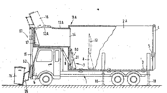
Figure 1 shows a simple embodiment of a trash collec-
tion vehiclel primarily in order to descri~e the basic
structure and functions of the present invention. A
collection container 2A is r~leasably fastened on a chassis
1, for example by locking members 3 as they are customary in
container transporting vehicles. The rear of collection
container 2A is configured as a discharge opening and ther2-
fore includes a pivotable rear wall 4. Rear wall 4 can be
10 pivoted open toward the top, and it can be held in the closed
position by locking members 5.
The trash collection vehicle is provided with a pressing
apparatus 60 which includes a pressing plate or pusher 7.
Pusher 7 is disposed in the interior of container 2A,
normally adjacent the end walI of cantainer ~A that faces the
driver's cab 6, and is guided so as to be displac~able within
collection container 2A in the longitudinal direction of the
container 2A. Push~r 7 is movable by an actuation mechanism
9, for example a telescoping hydraulic cylinder, which is
releasably connected with pusher 7 by a~oupllng 31. An
: opening is provided in the front end wall of collection
container 2A as shown,;~and the coupling 31 is manually ;j
ac~essible through this opening. When collection container
~: : 2A is completely ~ill d, as will be discussed in more detail
i,: :
SUI~STITUTE 5~E~ET
. ~ . .
:: : :
:
27 2 ~ 3 ~
i,.~ WO91/00231 - PCT/EP90/00992
hereafter~ this opening is closed by pusher 7!~ Actuation
mechanism 9 may be permanently disposed in collection
container 2A as an alternative.
Pusher 7 has two primary portions. It includes a base
member 8, to which the actuation mechanism 9 can be
connected, and an extension member 10 which can be raised
~ertically upwardly so that the pusher 7, with its extension
member 10 raised, covers almost the entire container cross
l~ section as shown in dot-dash lines. In its end position at
`, 10 the front wall and with extension member lO lowered,
collection container 2A has a fill opening llA ln its upper
region. This fill opening llA can be closed by extension
member 10.
An intermediate container 12A is permanently mounted
above driver's cab 6 and is provided with a fill opening 13A
in its ~orward region. The intermediate container 12A
extends essentially over the entir~ width of driver's cab 6.
At i~s rear end 14, intermediate container 12A has a
discharge opening which correspo~ds in size to~fill opening
llA of collection container 2A. The rear end 14 of
intermediate container 12A extends slightly into collection
container 2~ and bridges the gap between the end wall of
intermediate -ontainer 12A and the ~ear wall of driver's cab
6.
~3 ~ ;~
S~'~S~lTiJl~ SHEET
~: .
~, .
28 .~(
WO91/00231 PCT/EP90/00992
2 ~ 3 ~ With continuing refere~ce to Figure 1, a dumping
apparatus 61 is disposed at the front of driver's cab 6 as an
apparatus for manipulating the trash containPrs 16. Dumping
apparatus 61 includes a holder mechanism 26 which is
pivotably mounted on a caxriage ~2. Holder mechanism 26
cooperates wi~h elements (not illustrated) on trash container
16 so as to releasably grip the trash container 16. Carriage
62 is provided with rollers which extend into channels in a
pair of guide rails 15 that are mounted on the vehicle.
Guide rails 15 are part:of a trash container elevating
~ mechanism which also includes a drive mechanism (such as
hydraulic cylinders, not shown) for raising or lowering
carriage 62 along rails 15 and a further drive mechanism
(such as further hydraulic cylinderst not shown) for rotating
holde~ mechanism 26 with respec~ to carriage 62 when carriage
62 is at the top of the rails 15. After the trash container
: 16~is manually placed on holder me~hanism 26, dumping
apparatus 61 raises it from ground level to the region above
intermedia~e cantainer 12A, and:then~holder:mechanism 26 is
pivoted with respect to carriagè 62 so as to empty trash
container 16 into intermediate container 12A, Fill~opening
13A is shown only schematically. The fill opening 13A is
ad~isably proYi~d~d~ in the intermedia~e container 12AIin such
a manner that~ in conjunction with t~e dumping apparatus 61,
.
: ~ .
: ~ -
~ ' JBS~5TUTE St~EET:
29
:~ WO91100231 PCT/EP90/~0992
" '' 2 ~3 3
the pivoting of trash container 16 into the discharging
position causes the clearance profile of the vehicle (that
is, the normal height of the vehicle) to be exceeded at most
o~ly slightly.
Two (or more) dumping apparatuses may also be arranged
next to one another and actuated independently of one
another so that two trash containers 16 can be emptied
simultaneously, although this is not shown in ~igure 1.
The trash emptied into intermediate container 12 is then
pushed by a discharging apparatus 17 in intermëdiate
container 12A through fill opening llA and into collection
container 2A. The discharging apparatus 17 is illustrated
only schematically and may include a pusher as shown, in
. addition to associated equipment such as guides (not shown)
1~ for the rollers of the pusher and a hydraulic cylinder (not
showrl ~ ~or moving the pusher back and f orth along the guides .
Alternatively, a conveyor belt ~not illustrated) or floor
scraper (not illustrated) which moves the incoming trash int~
collection container 2A could be employed for discharge
apparatus 17.
At appropriate intervals, pusher 7 pushes the trash
whi ch has been discharged into th2 collection container 2A
.
~ toward rear~wali 4 so that, once the trash in container 2A
::~ reaches a certain fil} volume, ~he trash is pressed against
~: ~
SUBSTITOTE 5HIE~ET
. . .
WO91/00231` PCT/EP90/00992 ~
203~56
the rear wall 4 and thus compacted. Sufficient free fill
space is thus made available below fill opening llA ~or each
new discharge process from intermediate container 12A. In
the final phase, a small remainder can then be s~ueezed by
discharge apparatus 17 of intermediate container 12A into the
region of collection container 2A immediately adjacent fill
opening IlA, whereupon extension member 10 is raised to close
the filI opening llA completely.
The collection container 2A, which s thus filled
tightly and almost completely:with`trash, can then be driven
; to a depositing location and can there be set down by the
vehicle. In the embodiment illustrated in Figure 1, : :~
: : telescoping supports 18, which can be~extended downward and
~; locked, are provided for this purpose on the exterior of~
co}lection container 2A. After the extension of~supports 18,
: locking members 3 are released. Dapending on the type of :
th:e collection con~ainer, the locking members are raised
; somewhat~before~the supports 18~are:lo~cked or:the vehicle~is
lowered~somewhat~af ter~;the supports~ 8: are~locked,~:for:~
20 ~ example~ with~the~ a~id~of~the Yehicle's~air~suspension tnot ~
: illustrated)~ The~vehicle can~:then move~out from~underneath~;
the thus set-up~collecti~on containe~r ~A and~pick up a:~
ikewise support~ed:~empty c~ollection container before ::~
returning to it~s~l~assigned area. ~The~filled collection~con~
SUBSl lTUrE SHEeT
~ WO91/00231 31 PCT/EP90/00992
3 ~
tainers 2A can then be picked up by a purely tr~nsporting
vehicle (not illustrated) and driv~n to an unloading
location, be it an incineration plant or some other
depository such as a dump landfill.
The modified embodiment shown in ~igure 2 corresponds
generally to the embodiment of Figure l. Here, intermediate
container 12B extends rearwardly beyond driverls cab 6 and
covers a recess in collection container 2B. The plane of
~ill opening llB of collection container 2B thus extends
horizontally, and the associated discharge opening of
~ intermediate container 12B is disposed in the bottom, in
alignment with fill opening llB. Trash is pushed through
these openings by discharging apparatus 17~
Figure 3 shows a ~urther modification. Here, inter-
mediate container 12C is mounted above driver's cab 6 in a
horizontally displaceable manner, as by being suspended from
a guide 20 which is mounted on the~vehicle. A guide 34
which follows guide 20 is mounted on the ceiling of
collection container 2C, so that a drive mechanism (not
shown) is ~ble to move intermediate container 12C into
collection container 2C through ~ill opening llC.
~ Intermediate container 12C can be emptied, for example,
:` I th~ough a flap (not shown) in its bottom. In this
embodiment, the intermediate container 12C is filled in the
~;U 1~3sTlTuTE ~tt F~ r
.. , . ..... . . . ~ .. . ~ . . . .
WO91/00~31 32 PCT/EP90/00992 ~
2~35~5~
manner described above Guide 20 may also be disposed
directly on the roof of driver's cab 6 so that the inter-
mediate container l2C enters into guide 34 only when it
enters into the collection container 12C for the emptying
process
Figure 4 shows an em~odiment in which intermediate
container 12D can be moved from a fill position near the
ground in front of the driver's cab 6 to a raised position in
front of and over the driver's cab 6~, and then to an emptying
position at collection container 2D Intermediate container
12D is shown in dot-dash lines in its emptying position
Although not shown in Figure 4, intermediate conta:iner 12D is
emptied by a discharging apparatus 17~as described, for
example, in connectlon with Figure`~l ~Collection container
lS 2D itself is ~ery similar to the collection container 2A in
the Figure 1 embodiment, except that an overhang 59 is
mounted at the front end Wdll of collection container 2D to
reduce the risk: that trash might fall between the front end
wall and pusher 7
`20 In the illustxated embodiment, a~displacement apparatus
; l9 includes a guide 63 Which is mounted~on ~he vehicle above
driver's cab 6 This guide 63~may be provided,~for example,
` in the form of two parallel rails~which~are 5paced apart and
hich rollers hold Z~ thae are connected tc int-rmediate~;
, ~ ~
S U B S TIT U TE~ S H E ET ~ ~ ~
.. . ~ , ~
WO91fO0231 33 PCTtEP90/00992
container 12D. Alternatively, the rails may hold slides (not
shown~ connected to intermediate container 12D, or a carriage
~not shown) khat can be connected to intermediate body l~D.
Displacement apparatus l~ also includes a lifting
5 mechanism 22 which moves intermediate container 12D
vertically. Lifting mechanism 22 inc~udes vertically
extending guides 23 in which a lifting frame 24 can be moved
vertically up and down with the aid of a lifting drive ~5,
for example in the form of hydraulic cylinders or rapid
-lO thrust spindle drives (not:illustrated) driven by an oil
~otor (not illustrated). Lifting frame 24 is provided with
the appropriate rails ~or receiving intermediate container
12D.
A holder mechanism 26 of conventional construction may
be disposed at the front of lifting frame 24 for emptylng
trash containers into intermediate container 12D. Trash bags
may be thrown manually into fill opening 13D.
Displacement apparatus 19 al~o includes drive means for
advancing intermediate container 12D, in the xaised position
~as shown in Figure 4, by way of guide 63 int4 its emptying
posi~ion, and for retracting it again . In the illus~rated
embodiment~ a~hydraulic cylin~er 2J is pro~ide~ aslthe drive
means. It is fastened to lifting frame 24 and engages the
; ~:
; : bottom region of intermediate container 12D. However, the
.
SU13STITIJTE S~lE~T
::
~ :
WO9l/00231 PCT/EP90/00992 ~
2~3~`456
drive means may also be disposed in the region of.guide 63
and if a hydraulic cylinder is employed, for example, its
piston rod can be retracted to draw intermediate container
12D to the emptying position. Thus intermediate container
12D can be pressed against collection container 2D and
locked (it being noted that the emptying position of
intermediate container 12D is also its position when the
vehicle is being driven).
The rear wall of intermediate container 12D is closed by
at leas~ one loc~able ~lap 28. In the region of the
emptying position, shown in dot-dash lines in Figure 4, guide
63 is equipped with actuating means, for example in the form
of hydraulic cylinders (not illustra~ed). When the
intermediate container 12D is moved to the~emptying:~ 15~ p~osition, the actuating means is engaged and releases the
lock ~not illustrated) of flap 28 3nd/or~opens flap 28. :B~y
way of a discharging apparatus disposed in intermediate
container 12D but not shown~in Figure 4, the trash can now be :
:; ~ pushed out of the intermediate containe~ 12D~and~into:
20~ collecting container 2D. :~
Fig~re~S~shows a;;modified version of the~embodime~t of:
: Figure 4.~ ;The~displacement~apparatus~corresponds ess;entlially
in structure and function to~the~displacement apparatus l9 in
th~ bod~ment~of Flgur- 4. :The~dl~ferenc- in the F:gur-~S~
SuBsT~lTuT~E 8HEEr
~ WO91/0023l PCTlEP90/00992
~r
203~4
embodiment is tha~ the end of collection container 2E facing
driver's cab 6 has a stepped region at the height of
intermediate container 12E, with a fill opening for container
2E. Guide 63' extends over the stepped region of collection
container 2E so that the in~ermediate container 12E can be
~oved to a position above the fill opening. The guide 63'
may be fastened to the vehicle o~er its entire length, but it
is preferable to divide guide 63' (or rather the parallel
rails which form it) into a forward portion which is
10 connected to the vehicle over driver's cab ~ and a rear
portion which, in a manner corresponding to the embodiment of
Figure 3, is fastened to the collection container 2E over the
fill opening o~ the collection container 2E. In this
embodiment, intermediate container 12E has a front-end ~ill
opening 13E. More importantly, intermediate cQntainer 13E
has bottom flaps 29, shown in dot-dash lines, which can be
unlocked and opened to empty~ intermediate container 12E into
collection container 2E. After intermediate container 12E
has ~een emptied, the f1aps 29 are locked again by an
appropriate actuating means (not i1lustrated). The pusher 7
~: is moved back and forth over this re~ion of collection
¦: container 12 by actuation mechanism 9 to keep the region
l~ clear~
:
1~ :
1' :
1`~ SUBST5TU~E~ SHEFr
.,
36
WO9t/00231 PCT/EP~0/00992
~3~;~3~ j
~v In the embodiments of Figures 1, 2, 3, 4 and 5, the
collection container ~for example, reference number 2.~ in
Figure 1~ includes, at its fill opening (for example,
reference number llA in Fi~ure 1), a closing flap (not
illustrated) which is closed tightly as soon as the
collection container is to be released from the vehicle when
filling is completed.
The embodiment shown in Figure 6 depicts a collection
container 2F which is subdivided by a partition 64 into two
portions 33 and 33' and which is provided with two fill
openings on its upper side. Guide 65 has a rear portion 58,
for example in the form of rails, which is firmly connected
with the collection container 2F so that collection container
2F may be releasably connectediwith the chassis 1. The
collection container might alte~natively be configured
accordin~ to Figure 3 (that is, so that the intermediate
container 12F is able to move into it through an opening~.
Both end walls of collection container 12F ~an be opened
by pivoting a respective wall 4. The fill in container
portion ~3 can be compacted by pusher 30 and the fill in
container portion:33':can be compacted by pushe~r 30'.
Pushers 30 and 30'~, which are connected by hydraulic
c~ nders (inot!illustrated) to partition 64, clan aiso~be used
to push out the compacted trash after the resp~ctive wa~l 4
::
~: : SU5STIT~ITE S~IEET
~ ~ .
:
WO91~00231 PCT/EP9~/00992
has been opened. With collection container 2F, pre-sorted
trash can be collected with a single vehicle. The collection
container can, of course, be partitioned in various different
ways. If there are ~ore than two transverse partitions, the
collection container may be emptied throuyh respective
openings in the side wall. It is also possible to partition
it longitudinally. In this case, the intermediate container
must be provided with appropriately associated discharge
openings. If the partitioning is longitudinal, the collec-
tion container can be emptied and its fill compact d by meansof several parallel, independently guidable pushers. The
container portions may, as shown, form a closed unit.
Alternatively, they may be configured as separate container~
which can be connected with the chassis l so as to be
individually releasable. Each container portion may here be
equipped with its own pusher whose hydraulic cylinder can be
connected with the hydraulic supp;y of the vehicle by a plug-
in connection~ ; ~
Fi~ure 12 is a schematic top view and Figure 13 a cross-
sectional view of such a longitudinally divided collection
container, which is identified using reference number 2G.
Each of the container portions has a respective pressing
àpparatus with a pusher, identified here as pushers 66, 67,
~ ~ and 6-. For reasons of better weight dis ribution, the
: ~ SUB~;TITUT6 SHE~ET
WO91/00231- 38 PCT/EP90/00992 ~
233~4~ `
container portion intended for the type of trash occurring in
larger quantities may be arranged in the middle. Instead of
a single longitudinally partitioned collection container such
as container 2G, separate elongated collection containers
S (not illustrated) which can be releasably connected with one
another and with a base frame may be employed.
Figure 7 is a schematic top view of a collection
container 2H which includes a basic container 2a', which
simultaneously constitutes a base or supporting frame for
container portions which are provided by individual
containers 2b'~ 2c' and 2d'. The individual containers 2b',
2c', and 2d' are releasably connectable with basic contalner
: .2a'. The basic container 2a' and the individual containers
are provided with fill openings ~not illustrated) through
which pre-sorted trash can be drop~ed from an intermediate
container 2F that is movable on the rails of guide 58 (see
Figure 6). Depending on the particular case, the co~tainer
portions may ~e provided with ~ill openings which can be
charged independently o~ the intermediate container 2H, for
example in a respectl~e side wall. For example, paper could
may be deposited in individual container 2b', while special
re~use, for example from hospitals, could be filled into
: individual containers 2c' and 2d'. The individual containers
can then be released from the collection container 2H or from
'
SUE~ST'TUTE S~EET
:::
39
WO91/00231 PCT/EP90/00992
.~ ` 2~35~
the vehicle for emptying, and can be transported away without
being reloaded while the normal trash contained in basic
container 2a' is dumped in the usual manner.
Returning to Figure 6, a dumping apparatus 35 is
provided in the ~orm of a robot-type arm for manipulating
trash containers 16 to be emptied into intermediate container
12F. Dumping apparatus 35 is connected with the vehicle or,
more precisely, with the guide 65, so as to be pivotal about
a vertical axis 36. Dumping apparatus 35 includes an arm
section 37 whose length can be varied horizontally, as by
~ using a hydraulic cylinder, as well as an arm section 38
whose length can also be varied. Arm section 38 i5 pivotably
artlculated to arm section 37. With dumping apparatus 35 the
clearance profile of the vehicle (that is, the vehiclels
normal height) is not exceeded by very much during manipula-
tion of trash conkainer 16 and intermediate container 12F. A
~xipper mechanism 39 ~shown only schematically~ is disposed
at the free end of arm section 38 and is itself pivotal
relati~e to arm section 38 about at least one coordinate axis
:~ 20 so that practicall~y any type:of trash container can be picked
; up from the edge o~ the:road, precisely posit oned in front
: of intermediate container 12F, emptied into it by pivoting
thelgripper mechanism~9, and~put ~own again. Such a grlpper
mechanism 39 can be operated from the driver's cab or from an
~ S:U~STlTU~E SHE T ;~
WO~1/00231 PCT/E~0/0099
~1 2~3~4S~ `
operating station (not illustrated in Figure 6) disposed on
1 the side of the ~ehicle. Gripper apparatus 39 is equipped
;i with means (not illustrated) for opening and holding the
cover of the trash container 16 during the emptying process.
If configured appropriately, a gripper apparatus is able to
also pick up trash bags and smaller bulky pieces of rubbish.
Advantageously, if the gripper apparatus is pivotal about all
three coordinate axes, it will be able to pick up trash
containers standing at an angle to the edge of the road.
In all embodiments, the intermediate container can be
closed completely (although the closure is not illustrated in
some of the drawings). For example, a flap 28 as in Figure 4
or ~laps 29 as in Figure 5 may be used to cl~se the discharge
opening~ The intermediate container may also be provided
with a closable fill opening for the trash c~ntainers to be
empkied, with such opening being opened only during emptying
of the trash container. This may be accomplished by using
one or more covering fIaps tnot illustrated) for the fill
opening~ The fill opening o~ ~he intermediate container
may also extend over almost the entire length of the ceiling
of the container.
Returning to the embodiment of Figure 4, instead of a
~ holder mechanism 26, a pulverizing machine (not illustrated~
: may be disposed at lif~ing frame 240 With an appropri~tely
SUB~iTUT~ S~ET
~i~ WO91l00231 PCT/E~0/00992
; configured intermediate containex 12D (such as a con~ainer
, that is open at the top, not illustrated in Figure 4) such a
.i trash collection vehicle may also be used for collecting
;l .
;i bulky rubbish. The intermediate con~ainer 12D could be
.~ 5 emptied into collection container 2D after displacement,
either through an appropriate discharging mechanism (not
illustrated in Figure 4), through bottom flaps (not
illus~rated in ~igure 4), or by dumping.
In the embodiment shown in a side ~iew in Figure lO and
in a top view in Figure 11, intermediate container 12I is
;~ - fastened to a lifting column 69 with which the intermediate
' container 2I can be raised to above the height of the
i`!
~' driver's cab 6. The subsequent horizontal movement into the
i~ emptying position is performed by pivoting ahout the axis of
lifting column 69, so that intermediate container 2I is moved
in a horizontal plane, as can be seen in Figure 11.
In modification oP the embodi~ent shown in Figure 10,
lifting column 69 may also be disposed in the middle in
front of the driver's cab 6; the intermediate containex 12I
can still be brought into its emptying posîtion at the
collection container 2I by a pi~oting movement in the
horizontal plane.
~ Dependlng qn the dimensi~ons of the intermediate
container 12I and the driver's oab 6, the pi~otit~g process
, ~ S~J~3STITUTE SHEET
, ~ ~
WO91i~0231 42 PCT/EP90/00992 ~
2~3~4~5
may also be followed by a horizontal pushing moYement. Thls
is advisable, for example, in order to produce a tight
connection between the intermediate container 12I and the
fill opening of the collection container 2I.
The embodiment shown in Figures 10 and 11 can also be
modified, with respect to the horizontal displacement
movement, so that the intermediate container 12I is pushed
into the collection container 2I after the pivoting process,
in a manner similar to that shown in Figure 3. Furthermore,
10 if a partitioned collection container according to Figure 7
is employed instead of collection container 2I, after
pivoting the intermediate container 12I can be moved, by way
of guides 58 on or at the container, to a posîtion above the
fill opening of the appropriate container portion. For a
lS longitudinally partitioned container as shown in Figures 12
and 13, the pivoting process is advisably followed by
shifting the intermediate container 12I in the transverse
direction above. the driver's cab 6 so that the intermediate
container 12I can be emptied into the ~ppropriate container
portion. The intermediate con~ainer 12I may be provided with
a holder mechanism 26 as in Figure 4 Qr with some other
manipulating mechanism, for example in the form of a robot
arm as in Figure 6.
.
SUE~STITUITE ~H~T
43 . 2~4~
WO91J00231 PCT/EP90/00992
The most desirable embodiments including a mdvable
intermediate container are embodiments in which, after the
lifting process, the intermediate container is moved only in
a horizontal plane, so that at no time is the greatest
permissable height exceeded.
Figure 8 shows a further embodiment in which displace-
ment apparatus l9" includes a closed supporting frame 70
which is connected with vehicle chassis l. Supporting frame
70 is provided with a guide 71 above driver's cab 6 and with
drive means (not illustrated) for moving intermediate
- container 12J horizontally. Intermediate~container 12J has
an open top as its fill opening. Displacement apparatus l9l'
also includes a lifting mechanism 72 (which is not shown in
Figure 8 and will be described later with reference to Figure
lS 9) for the inter=ediate container 123. Vertically extending
guides 23' for the lifting mechanis= 72 are rigidly connected
to guide 71, which includes a shie~dedi portion 73:and an open
portio~ 74. The open portion 74 of guide 71 extends forward
of the guides 23'. The shielded portion 73 o~ guide 71 is
configured in the form of a rectangular channel that is
~ : closed on four side~ and that extends from guide~ 23' to a
:~ transfer region 40 aboYe fill opening llJ of col~le~ction
: container 2J. Transfer region 40~is tightly connec~ed a~ its
bottom ~y way o~ an intermediate seal 41 with the fill
:
SU~TITUTE SH~ET
, .
`. ~
~a3~4~3 44 ~f'
W~ 91tO0231 PCT/~P90/00992 ~ i`
- opening llJ of collection container 2J. With the aid of the
drive means (not illustratPd~/ for example ~n endless
revolving chain drive mechanism extending horizontally in
guide 71, intermediate container 12J can be moved back and
forth along guide 71 by a carriage 42 which is configure~ as
a cover plate. The drive means may alternatively be a
hydraulic cylinder corresponding to hydraulic cylinder 27 in
the embodiment of Figure 4, except that the cylinder is
advisably fixed, together with carriage 42 and the piston
rod, at the rear end of the guide 71. In the emptying
~ position, which is simultaneously the driving position, th~
piston/cylinder unit would then be pushed together. The
horizontal movemenk of the intermediate container 12J can
also be effected by means of other drive systems, for example
oi} motors (not illustrated) or electrlc motors (not
illustrated). The width of the rectangular channel provided
by shielded portion 73 is such th~t it i5 able to accommodate
intermediate container 12J together with its carriage-like
coYer plate 42. Rear wall 40' is closed.
The supporting frame:70 of displacement device 19l' is
articulated to the front end of the vehicle chassis at two
~astening points 43O It is also supported on an abutment 75
fqr actuatin~mechanism 9 at a fastening point 44,'so ~hat a
three-point support is provided. Fastening point 44 is
SU~STITUTE~ SHEET
.... ..
~ WO91~00231 PCT/EP90/00992
~5~6
configured as a joint so that vehicle chassis l is able to
freely buckle rela~ive to the supporting frame 70, which is
inherently rigid. The fastening point 44 may be a universal
joint which permits transverse displacement of the abutment
75 relative to the supporting frame 70.
A hydraulic cylinder 45 is connected on each side of
supporting frame 70. The hydraulic cylinders 45 can raise
the supporting frame 70 by a slight amount from the
illustrated horizontal position ~the operating position~ so
that fill opening llJ is exposed and collection container 2J
can be separated from the vehicle. Hydraulic cylinders 45
are dimensioned in such a way that they can also pivot
displacement device l9 " forward~into the position sho~n in
dot-dash lines. This permi~s driver's cab 6 to also be
pivoted in the conventional manner to the position shown in
dot-dash lines so that repair or~maintenance work can be
performed on the vehic}e engine. : ~
The mod~ of operation of th~:dispIacement:apparatus l9''
of Figure 8 oth~rwise correspqnds to:that of displacement
apparatus lg descri~ed in connection~with Figure 4 and
displacement apparatu 19' described in:connection~with
Figure S. The trash containers ~not shown in Figur~ &~ are
emptied by way of a holder mechanism (not shown in Figure 8~
into the intermediate contamer~l2J, which is shown in Pigure
SUBSTITUTE SHEET :
:: : ~ : :
WO9l/0023l . 46 PCT/EP9~/00992~ `
` 2~3545~ ~
8 in dot-dash lines in its fill position near the ground.
Then, by way of the lifting mechanism 72 (see Figure 9) the
intermediate container 12J is lifted until it abuts against
the carriage 42 and is locked to it. Thereafter, the drive
S means (not illustrated) provided in guide 71 moves the
carriage 42 together with inte~mediate container 12J out of
the lifting mechanism into the shielded portion 73 of guide
71, and then to the emptying position. Here a closing flap
(not illustrated in Figure 8) which forms the rear wall of
the intermediate container 12J opens and the trash contained
in intermediate container 12J is pushed out by a discharging
apparatus 17 (which may, for example, be dri~en by a
hydraullc cylinder as shown) into transfer region 40 and
drops into collection container 2J through fill opening llJ.
Inside collection container 2J, pusher 7 pushes the trash
into the rear portion of collection container 2J. Pusher 7
is advanced by actuation mechanism 9 (s~ch as a hydraulic
cylinder) until it has swept over the region ~ene~th fill
opening llJ, which lies in a portion of collection container
12J ha~ing a relati~ely low ceiling. Due to the relatively
low ceiling, the forward portion of collection container 2J
has a smaller container cross section than the rest of "
collection cont:ainer 2J. The trash is pressed from the
~- region of the~small container crosC section to the region-of .
~ ~L iT~TE ~tET
.
~ WO9l/00~31` PCT/E~0/00992
`- ' 2~5~5~
the large container cross section and almost completely
fills the larger cross section region of collection
container 12J due to the structure of the trash in ~he final
filling phase.
The shielded portion 73 of guide 71 encloses
intermediate container 12J during~its horizontal range of
movement, all the way to the transfer region 40. This keeps
trash from being blown out throu~h the open top of
intermediate container 12J. In any event intermedia~e
0 container 12J is closed by carriage 42 during the horizontal
movement. The lifting mechanism 72 shown in Figure g may be
used in order to also shield intermediate container 12J
against the outside during the vertical lifting movement.
Like the li~ting mechanism~22 in Figure 4, the lifting
: 15 mechanism 72 shown in Figure ~ includes~a lifting frame 24
. which is mounted on guides 23' fo~ up and down movement.
Lifting mechanism~72 aleo includes a lifting drive,:~although
this is not shown in Fi~ure 8 for the sake of clarity.::A
lifting drive 25 as describeù in conjunction with ~igure 4
~may be used. Unli~e the:Fi~ure 4 embodiment, lifting ~ :~
mechanism 72 also has a ~ariable length cover 46. Cover ~6
includes a ~ellows 47 which has a basically C-shapeld cross
section and encloses~the:lifting region:on the s~ides and
t~ward the driver's~ cab 6. ~Bellows 47~is open toward the:
; :: SU~T~TUTE :SH~ET
: `: . ~ :~
, ~ i ~; : : :
WO91/00231 48 PCTIEP90/00992 ~
2 ~ 3 ~ 4 ~ ~ront, with respect to the direction of travel. This opening
is closed by a strip curtain 48. The bottom end of bellows
47 is fastened to intermediate container 12J and the top end
is fastened to carriage 42. After it has been completely
filled, intermediate container l2J is rai~ed by lifting frame
24 and pressed ag~inst carriage 4Z, and while this occurs
bellows 47 is pushed together and is partially rPceived by
recesses 49 in carriage 42. The bottom end of strip curtain
48 is fastened to a handle 76 which can be removably clipped
onto intermediate container 12J. The top end is attached to
a winding mechanism 50 that is connected to carriage 42.
Since at least part of the front region of cover 46 can be
opened, the trash contain~r (not illustrated in Figure 9) to
be emptied can be moved through with t~e aid of a holder
mechanism 26 so as to empty it into the upwardly open
interme~iate container 12J without noticeable quantities o~
dust or refuse escaping. As soon~as intermediate container
12J is locked to carriage 42, the entire system including
cover 46 can be moved to the emptying position shown in
Figure 8. Lifting frame 24 remai~s in the raised position.
In the fill position of intermedia~e container 12J near
he ground as~shown in Fi~ure 9, cover 46 obstructs the
river's ~iew:;im~ediately toward the front. However,`this
generally does;not matter since the lifting mechanism 72 of
: ~
:~
SU~STITUTE S~EET
4~
~O91/00231: -PCT/E~0100992
2 a ~
displacement device 19 is able to quickly raise intermediate
oontainer 12J and lifting: frame:24~;and thus enable the
d~iver to see again. If small trash containers are to be
emptied at different stops a~long a relatively long route, the
intermediate container~12:J may have:~to be moved up and down
: several times to enable the vehic:le to move on before it is
: : :
completely filled. On the other hand i~ large-~rash
containers are to be~emptied, for example:~at:mult~i-family
:dwellings,~ or~if:a~large:number of~smaller trash containers
are~set out next to;:;one~another~,;the~:intermedlate:contalner ~ :
12J is generally filled completely at one pickup location
and can then be emptied~into:the vehicle as the:vehicle is :
driven to~the~ next~p~ickup~:location::during :the horizontal
movement~and duri~n~g:~the~:emptying:process.
: ; 15~If~bags-~(not `illustrated):~are to :bé employed for the ::~
.. ~
trash~, instead of~trash~;containers,:~and if such bagsl~are~to
~ be~dropped~into~'thé~opeD~top~o't~;~lntermedlate conta:iner 12J~
'~ without~being~emptied,¦it would be desirable for~ carriage:4:2
to~ include~:a:~pressure~p~late~whiGh is~actuated when~
';~ ;20'~ inte ~ ediàte~o i ~12J~ s~ thel~raised:;pos i~on~;to~
` m ress ~ ~cont'ni .;~ Such~'~a~pressure~plate~woul ~be ~
carr~ied ~along~by: carri~age~42:during~;the ~horiz~ontal~movemlqnt
of!intermedI'atè~`container 12J~;unt~ the latterl~has rea~ched~
ts~emptying ~ n:~above the collecOion container ~J.
5UEisTlTUT~ T;
1`
WO 9ttO0231 PCTJE~0/00992 ~ ~`
2 ~ 3 ~ r
Instead o~ a separate pressure plate, however, the fill
opening at the top of the intermediate container 12J may be
closable with flaps (not illustrated) which are fastened to
intermediate container 12J~ In embodiments without cover
46, such flaps could be folded open enclose the fill opening
on three sides to thus fvrm a protection shield against the
wind during emptying of the trash containers into the
intermediate container 2J.
As can be seen from Figure ~, a space exists between
-10 the rear of driver's cab 6 and the front wall of collection
container 2J and outward of the a~utment 75 for ac~uation
mechanism 9. This space is sufficient for a protected worker
.station where the worker can stay during travel between two
relati~ely distant pickup locations for trash containers. A
ladder 51, which is provided to permit con~enient access to
the upper regions of the yehicle,~is mounted by hinges (not
illustrated) on one side and has a latch (not illustrated) on
the other side. This permits the ladder 51 to also serve as
a latchable door to the worker station, Pnsuring that the
20~ worker will not be flung out of the worker station.
Althou~h not shown to avoid obscuring ~he drawings, the
wqrker station~may also be pro~ided wit;h wails at ~he top and
on three sides to:protect the worker against the weather
~;during his stay at this location.~ At the same time, the
`
`
;W BSTITlJTE SHI ~El~
`
~` :
~ WO91~023t` 51 PCT/EP90/OOg92
- 2 ~ 3 !~
worker has a sec re position here during travel even if the
vehicle is forced to brake suddenly.
Figures 14A to 14G show, f or better understanding, the
sequence of the individual functions with referencP to a
vehicle of the general type shown in Figures 8 and 9. Some
o~ the elements shown in Figures 8 and 9 are not depicted in
Fi~ures 14A to 14G to avoid obscurLng the drawings, and it
should be noted that the holder mechànism 26' and the ladder
51' in Figures 14A to 14G are modified forms of the holder 26
and the ladder 51 in Figures 8 and 9. Additionally, the
vehicle shown in Figur~es 14A to 14G has horiæontal hydraulic
cylinders 45' for pivoting the supportin~ frame instead of
he vertical hydraulic cylinders 45 shown in Figure ~.
~` ~ Figure 14A shows the emptying of a large trash container
:~ ,
~; 15 16 ' into the intermediate container 12J, which is in a
~ :
position near the ground. The~space ab~ove the interm diate
container 12J is enclosed by cover 46 so that trash container
16' can be pivoted~into this area through the strip~curtain.;
Figure~14B~shows the lifting process.
~20~ ~ Figure 14C~shows~the displacement o~intermediate
container 12J in the channel like guide 71 until it reaches
he emptying position.~ Lifting frame~24 is held in the~
raised position.
u~s~l~urE ~;HEET~
52
WO91/00~31- PCT~F~0/00992 ~
2 0 3 ~ 4 ~ ~ Figure 14D shows the emptying of intermediate container
12J into collection container 2J, with a rear closing flap
77 on intermediate container 12J releasing the discharge
opening of intermediate container 12J.
Figures 14E and 14F show the return movement of inter-
mediate container 12J. Figure 14F also shows the pushing of
the trash to the rear region of collection container 2J by
pusher 7.
Figure 14G shows thè vehicle with displacement apparatus
19 " pivoted slightly forward1y and with ground supports 18
extended from collection container 2J. By lowering the
vehicle relative to the collection container 2J in the manner
customary for interchangeable bodies J the vehicle is released
from the collection container 2J and is able to move forward.
A new, empty collection container can now be pic~ed up in the
reverse sequence. If maintenance and/or repair work is
required for the engine, the displacement can be pivoted
further into the position shown in ~igure 8.
In the embodiment shown in Figures 14A.to 14G, the
stationary ends of the hydraulic cylinders 45' are
articulated to the upper portion of abutment 75. This has
the advantage, inter alia, that more space is available for
, , , . I ` , : i ; ! ~1 `
~ the worker station behind laddex 51', i~ c~mparison with the
; : arrangement shown in Figure 8.
` ~ SUE~STITUTE 5HEET
r'~ WO ~l/00~31- 53 PCT/FP90/00992
,~ . .
~ 0 3 ~ 4 5
The vehicle can be driven only if the intermediate
container has been raised. Although not shown, this can be
accomplished by additional safety maans which are connected `
with the controls for the displacement apparatus, for example
in the form of a so called interlock which permits release of
the brake only lf the intermediate container has been raised.
Figure 15 is a perspective view of a collec~ion con-
tainer 2X for use with a vehicle according to Figure 8 in
lieu of collection container 2J i~ pre-sorted trash is to be
1-0 collected as described already in connection with:Figures 12
and 13. Collection container 2K may be configured as a
unitary component so that the container portions 7~, ~9j and
80 are formed by longitudinally extending partitions.
i
~: Collection container 2K might also~be~composed of three
: lS narrow individual containers which are connected with one
1-
another by releasable locking mean~ (not illustrated) to form~
a:;comp~ct unit which can be pla~ed on:~o the vehicle and can .
~.
:~ be released from it again~ The fil}ed individual containers
can then~be moved separately;to different dumping locations~
The fill openings llK of the container~por~ions 78~, 79,::~
and 80 may be closed by separate:closing flaps 81 once the
c,onltainexs have been released from:~ithe~vehicile.l;Fu~the~ore
~he rear wall of collection co~tainer is divided int~ three ~:
piYotable portions 4 ' . AccordingIy,~the three container~
S ~ ~3 ST~ T U
WO91/00231 54 PCT/E~0/00992 ~ ~
`2~3~S~
portions can be fi11ed and emptied separately. Although not
shown in Figure 8, transfer region 40 should be subdivided
above fill opening 11k by corresponding meta1;partitioning
sheets if co11ection container 2K is to be used.
In order to prevent in~dvertent mixing of the diff~rent
types of trash in the fill region of the partitioned intPr-
mediate container 12K when trash containers are emptied,
partitions (not illustrated) may also be disposed in the area
enclosed by cover 46 (see Figure 9) above the intermediate
cantainer, with the length of t~ese partitions being Yariab1e
to correspond to the lifting stroke.
In the emobodiments shown in Fig~res 4, 5, 6, 8 and
10 or raising and lowe-ing the intermediate container 12
ln frGnt of the dirver's cab 6 a 1i~t~1ng device could ~e used
as it is known in pri~ciple from fork-1ift-truc.~s. As shown
schematica11y in Figure 16, ~his~ 1ifting de~ic~ compri~es
at least ohe hydraulic cylinder 82, the free end o~ lts
piston rod 83 carries a roller 84. This roller 84 is wor.~inS
:20 on a s~r~cket chain 85~with Qne end 86 fastened at a bottom
part of the ~ehi1e,~the sproc~et cha1n 85 passing ove~
aforesaid rol1er 84 and wlth its other end 87 afrixed to
the 1i~ting rame 24, so that the lifting frame can be
mo~ed ver~ically from;its~filling position ln ~he battom ~ -
region to the top region~for couplin~ the intermediatecontainer with the drive meansO
~;U~3~T~T~JIT
~ ~ WO9}/00231 55 PCTJEP90/0~992
'`!~` `-` i i
~3~
The dumpin5 a~?ara~ls 35 s;~own in Figure 6 c~n 3e
adoDte~ for all e~odi~en.ts 0~ t~e in~e~tion, wher~ t-ne
~ inter~ediate container 12 is l~ d ~er~ically and t:~n
.~
~1 moved hori~ontall~J to the collec_~ on contzine- 2. I- is
~ 5 an adavntage o~ t;~is dumpin~ àDparatus 35 in connec=- on
,~: with the system of an lnt ~ed~ 2t- cont~lner acc~rd~ n~
~ to the invention ~ that both par;s can move ~reC~ ly wl .hout
.~ any collisio during their res?eC=ive movement.
r ~
LO It will be unders~o~d that ~1~ abave desc--~p.icn ~f t-~
pres2nt invention i5 sus~:2~ible ~ arious madi_ic~ s,
~ ` :
~ c;lanqes, and adaptati~nS, and ~he :same a~e~ inte~ded t~ ke
; ~ c~m~rehended wit~in the me2ninq and range~: o~ equival enls c~
the ap~ended c7 aim,.
SUDSTITUTE SH E~T