Note : Les descriptions sont présentées dans la langue officielle dans laquelle elles ont été soumises.
CA 02035786 2000-03-31
2'6666-48
Indicator-nut threaded coupling with load-indicatinct device
adapted to be arrancLed on anchors in particular ctrouted
anchors for mining' or the like
The present invention relates to an indicator-nut
threaded coupling with load-indicating device, adapted to be
arranged on anchors, in particular grouted anchors for mining
or the like, it consisting of at least one free space lying
on an outer wall surface, which space is narrowed and
possibly closed when a certain limit load is exceeded.
Such an indicator nut threaded coupling with load-
indicating device is available on the market, a bipartite hex
nut being screwed on an anchor instead of a normal anchoring
nut. This hex nut consists of an anchoring nut developed as
load-bearing part and a test part facing the abutment. On
the outer wall of the indicator nut there are slits which
narrow and possibly close when a given limit load is
exceeded, the nut ribs of the test part shearing off. As
soon as the slit is closed, the anchoring force increases
again rapidly up to the breaking load of the anchor. The
slide path for the anchor which is freed by the yielding
indicator nut is relatively small and frequently not
sufficient for movements of strata or the like.
The object of the present invention is to make the
manufacture and handling of an indicator nut threaded
coupling with load indication simple so that, while it is of
only relatively slight structural height, a sufficiently
large slide path of an anchor is assured.
-1-
CA 02035786 2000-03-31
26666-48
The invention provides in an indicator-nut threaded
coupling comprising a load-indicating device adapted to be
arranged on an anchor, particularly a grouted anchor for
mining or the like, wherein said load-indicating device
defines a free space on an outer surface thereof, and wherein
said space is narrowed and possibly closes upon exceeding a
given limit load, the improvement in the indicator-nut
threaded coupling comprising a nut engageable with the anchor,
said free space is formed by a plurality of grooves, each of
said grooves being formed with a fold bottom, and wherein
said load-indicating device comprises a bushing associated
with said nut and extending spaced from an outer surface of
the anchor, said grooves being arranged in an outer wall of
said bushing, and wherein resistance to folding of individual
of the fold bottoms differs from each other.
The invention also provides in an indicator-nut
threaded coupling comprising a load-indicating device adapted
to be arranged on an anchor, particularly a grouted anchor
for mining or the like, wherein said load-indicating device
defines a free space on an outer surface thereof, and wherein
said space is narrowed and possibly closes upon exceeding a
given limit load, the improvement in the indicator-nut
threaded coupling comprising a nut engageable with the anchor,
said free space is formed by a plurality of grooves, each of
said grooves being formed with a fold bottom, and wherein said
load-indicating device comprises a bushing associated with
said nut and extending spaced from an outer surface of the
anchor, said grooves being arranged in an outer wall of said
bushing, and wherein said grooves are of different depth.
Preferably the grooves are arranged along the length
of the bushing at equal spacing from each other, the resistance
to folding of the individual fold bottoms differing from each
other. In each groove preferably the width is a multiple of
the depth, the grooves being of different depths.
-la-
As a result of this development, an indicator nut
threaded coupling with load-indicating device which is of
increased value in use and increased safety is obtained. zn
this connection, one proceeds in the manner that the free
space is formed by at least one groove which is provided with
a fold bottom and is arranged in the outer wall of a bushing
associated with the nut, the bushing extending at a distance
from the outer surface of the anchor. An indicator developed
in this manner serves to indicate the instantaneous maximum
anchoring force of the anchor. Any anchoring farces which
result from strata movements are conducted via the anchoring
nut into the bushing, the groove narrowing and possibly
closing when a given limit load is exceeded. This takes
place in the form of a bulging in the region of the fold
bottom of the groove arranged in the outer wall of the
bushing, the bulged material traveling into the free space
between bushing and outer surface of the anchor. When the
indicator has bulged together in clearly visible manner upon
the exceeding of the permissible anchoring force, the
anchoring force can increase to the breaking load. The
bushing, which is developed as load-indicating device, is
preferably made from a seamless pipe produced from fine-grain
structural steel ST.52 and normalized by subsequent heat
treatment. Thus, the bushing has very uniform strength
properties over its entire cross section. In this way, an
indicator is created which visibly indicates stresses and the
permissible loading of the anchor. As soon as the
permissible anchoring force is exceeded, the indicator
commences to flow uniformly and frees a relatively large path
of deformation. For stabilization against lateral evasion,
the bushing is provided at each of its two ends with a
°2~
support collar. This development assists in a radially
symmetrical bulging and folding as planned. zn the region of
the anchor plate this is further supported in the manner that
an edge reinforcement is welded on the bushing. One
advantageous further development consists therein that the
width of the groove corresponds to a multiple of its depth.
In this way, a bulging of the bushing according to plan is
assured, the width of the groove corresponding approximately
tp the slide path of the anchar. This slide path can also be
increased by providing several grooves arranged in rows
spaced uniformly from each other. The ribs remaining between
the grooves serve in this connection as stabilizing rings
against,kinking of the bushing. Experiments have shown that
a radially symmetrical bulging is present if the groove width
is in a ratio of 1.5 to l to the rib width, the groove width
remaining less than ~.0 mm. For the indicating of several
loading steps, the resistance to folding of the indivi.c~ual
fold bottoms differ from each other. The indicator thus
shows at least two load steps in addition to the maximum
load: It can be provided that the resistance to folding of
the groove lying next to the anchor plate is the smallest, so
that this groove width bulges upon a given stressing. This
bulged groove can, for instance, indicate that the anchor is
stressed by means of an impact screwdriver. Only when the
permissible anchor force is exceeded do the other grooves
bulge in accordance with thea.r resistance to folding. The
indicator can thus indicate digferent load values defined in
bulging tests. Finally, the resistance to folding of tha
individual fold bottoms is advantageously developed in the
manner that the grooves have different depths. These groove
depths, which are necessary for the individual load stages,
-3-
~~ ~ 3'~8~
can be produced very easily and accurately and be checked by
bulge tests.
Other advantages and details of the invention will be
described in further detail below with reference to an
embodiment shown in the drawing, in which
Fig. 1 is a side view of a load-indicating device
according to the invention;
Fig. 2 is a side view of the load-indicating device;
Fig. 3 is a longitudinal section through the load
indicating device of Fig. 1;
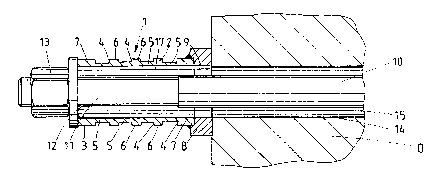
Fig. 4 shotas a grouted anchor provided with an anchoring
nut, the load-indicating device being associated with the
anchoring nut;
Fig. 5 is a showing corre~;ponding to Fig. 4, but also
showing bulging of a groove having the weakest resistance to
folding;
Fig. 6 is a sequential showing to Fig. 5, but upon the
bulging of another groove; and
Fig. 7 is another sequential showing 'to Fig. 6, in which
all grooves of the load-indicating device are bulged.
The load-indicating device l shown in Fig. 1 is formed
of a seamless bushing 2. In the outer wall 3 of the bushing
2 there are provided four grooves 4 arranged in a row at a
uniform distance from each other. These grooves 4 have
groove depths of different size, so that the fold bottoms 5
remaining as residual annular cross section have different
resistances to folding. The groove width is so dimensioned
that it corresponds approximately to 1.5 times the width of
the ribs developed as stabilizing rings 6 which remain
between the grooves 4. At each of its two ends the bushing 2
is provided with a support collar 7 which is of approximately
>~~~~~6
twice the width of a stabilizing ring 6. At the end region
in which the groove 4 having the largest groove depth, i.e.
having the smallest resistance to folding of the fold bottom
5, is located, an edge reinforcement 8 is welded to the end
of the bushing 2. This edge reinforcement 8 is of larger
diameter than the bushing 2 but has an axial hole 9 the
diameter of which corresponds to the inside diameter of the
bushing 2.
The mounting shown in Fig. 4 has a tension member in the
form of an anchor 10. As a rule, it consists of high-
strength bar-shaped tension steel material. The anchor head
11 which extends freely from the object O has an external
thread 1~. This thread cooperates with 'the inner thread of
the anchoring nut 13. The actua:L anchoring region, for
instance in a section of rock of a slope or the like, has not
been spawn in detail, The exit end, on the other hand, shows
a section of a bore hole 2~ which leaves a free annular space
15 concentrically around the anchor cross section, The
inside diameter 'thereof is so dimensioned that fissure
displacements perpendicular to the anchor 10 which are to be
expected do not lead to a shearing notion. After the setting
of the mount and the dying away of the strata deformations,
the annular space 9 is generally filled with cement mortar.
The load-indicating device 1 is arranged between the
anchoring nut 13 provided with a washer 16 and the outer
surface of the object O. The bushing 2 of the load-
indicating device 2 extends in this connection spaced from
the outer surface of the.anchor and is so arranged that the
edge reinforcement 8 rests against the outer surface of the
object O.
The fold-bottom cover of the fold bottom 5 of the groove
4 adjacent the edge reinforcement 8 is the thinnest, with the
result that when a given force in the direction x is
exceeded, this groove 4 is bulged (sea Fig. 5). By this
closing of the free space (groove 4), it can thus be noted
from the outside that a force is acting in x direction. The '
force which is indicated by the closing of this free space
has been previously defined in bulge tests. There is also
the possibility of using this groove 4 as control indication
for prior stressing. In this case, the anchor l0 is brought,
by means of an impact screwdriver acting on the anchoring nut
13, to a previously defined prior stressing, the flow of
force also taking place in x direction and thus effecting a
closing of the groove 4. The bulged fold bottom 5 of the
groove 4 grows as annular bead 16 into the free annular space
17 between the bushing 2 and the outer surface of the anchor
shaft.
When another defined anchor force in x direction is
exceeded, the groove 4 provided with the next thicker fold
bottom 5 bulges (see Fig. 6). Tf the anchor force in x
direction exceeds a permissible maximum value, this can be
noted from the fact that alI four grooves 4 are bulged. Thie
indication is visible from all sides and can be noted even by
untrained personnel: As can be noted from Fig. 7, the load
indicator 1 has a practically flat surface of the bushing 2
in this state in which of the permissible anchor force is
extended. This is a signal that the anchor force can now
increase up to breakage load. This signalling can further be
supported in the manner that the outer wall surface of the
bushing 2 is provided with a signal color. When the
permissible anchor force is exceeded, the color applied to
the stabilization rings 6 and the support collar 7 acts as
-6--
further optical signal.
Tn the case of the load-indicating device 1 described as
example, the ratio between groove width and width of the
stabilization rings is indicated with a value of about 1.5 to
1. The deformation path of the load-indicating device 1
corresponds approximately to half the structural height of
the load-indicating device 1. Thus a sufficiently
dimensioned slide path of the anchor 10 is obtained with
relatively low structural height.
The features of the invention disclosed in the above
specification, drawing and claims can be of importance for
the reduction to practice of the invention both individually
and in any desired combination. All features disclosed are
essential to the invention. There is herewith also included
in the disclosure of the invention the entire disclosure of
the corresponding/attached priority papers (copy of the prior
application).